-
PDF
Hauptplatine.pdf
PIU309 R2OUT R2IN PIU308 COC9 PIP3033 C 22pF Y1Y PI13012XTAL2 GND PI11031 100nF GND 15 6 9 RS232 C 16MHz PIU1013XTAL1 GND PIU1011 PIU3015GND VEE PIU306 PIC902 PIC901 C5 Y0 Cap Pol1 PIC501 PIC502 GND COP132ACPE 10uF GND Cap ATmega16-16PC VCC P12 22pF PIP12011 PIP12022 Summer VCC P131 GND CSPIP13011 2
in „AVR Wecker mit Netzwerk“ · Mikrocontroller und Digitale Elektronik ·
-
Datei
TLC_5940_Demystifying.c
define outputState(port, pin) ((port) & (1 << (pin))) #if (12 * TLC5940_N > 255) #define dcData_t uint16_t #else #define dcData_t uint8_t #endif #if (24 * TLC5940_N > 255) #define gsData_t uint16_t #else #define gsData_t uint8_t #endif #define dcDataSize ((dcData_t)12 * TLC5940_N) #define gsDataSize ((gsData_t
in „TLC5940 am ATmega16“ · Mikrocontroller und Digitale Elektronik ·
-
Datei
main.c
/* * * Created: 26.08.2021 12:01:13 * Author : Joachim J. * MC: ATmega 328p mit 16MHz / Arduino Nano */ #include <avr/io.h> #include <avr/interrupt.h> #include <util/delay.h> #include <stdio.h> #include <stdlib.h> #include <util/atomic.h> /*-------- Define --------*/ #define FOSC 16000000 //Clock Speed #define BAUD 19200 //Debug #define MYUBRR FOSC/16/BAUD-1 #define LED_PIN PC0 #define LED_ON PORTC |= (1 << LED_PIN) #define LED_OFF PORTC &= ~(1 << LED_PIN) #define set_cap_low_high TCCR1B |= (1 << ICES1); //Bit setzen: Capture von low zu high / rising
in „Servo-Pulssignalläge messen mit Atmega328p“ · Mikrocontroller und Digitale Elektronik ·
-
PDF
_Schaltplan.pdf
0u1 PC5 24 PC4 23 GND GND GND GND GND 22 PC3 21 GND PC2 20 VCC (SDA)PC1 19 C R4 (SCL)PC0 R7 1k5 X8 C 16 TCK 1 2 GND V 1k5 (OC2)PD7 15 3 4 (ICP)PD6 TDO VCC V1 (OC1A)PD5 14 TMS 5 6 RST BC807 (OC1B)PD4 13 VDC 7 8 (INT1)PD3 12 S3 TDI 9 10GND (INT0)PD2 11 R16 2 8 3 8 (TXD)PD1 10 3 1 JTAG R 6 R 6 (RXD)PD0 9 4 2 3k3 GND S2 8xLED red ATMEGA16-16AU A 3 1 R17 V8 R26 N 0 V2 4 2 G 1 IR-LED S1 3k3 1k5 V9 R27 D R5 3 1 R18 N GND 4 2 1k5 G 1k5 3k3 V10 R28 D V3 VCC S0 N R19 1k5 G VCC VCC R6 3 1 V11 R29 D OUT OUT 4 2 3k3 N GND GND 1k5 1k5 G C9
in „SI4713 über SPI mit einem Atmega“ · Mikrocontroller und Digitale Elektronik ·
-
Datei
Fmeter_GPS.c
/* Beispielprogramm 'reziproker Frequenzzaehler' mit GPS-Signal stabilisiert fuer ATmega162 und AVR-GCC. Funktionsbereich etwa 0,004Hz - 250kHz bei 16MHz Prozessortakt Neben der üblichen Frequenzmessung an ICP1 wird zusätzlich über ICP3 die interne Taktfrequenz anhand eines 1pps GPS-Signals
in „reziproker Frequenzzähler, GPS-stabilisiert, ATmega162“ · Projekte & Code ·
-
Datei
RFM01_RX.asm
**************************************** ; todays project: ; control The RFM01 RX Module with an ATMega 48/168/328 ; Receive an FSK data stream with it ; constants @ 16 Mhz clk ; ****************************************************************** ; crystal osc. frequency .equ F_CPU = 16000000 ; this is
in „Problem mit RFM01/RFM02“ · Mikrocontroller und Digitale Elektronik ·
-
Datei
RFM01_RX.asm
**************************************** ; todays project: ; control The RFM01 RX Module with an ATMega 48/168/328 ; Receive an FSK data stream with it ; constants @ 16 Mhz clk ; ****************************************************************** ; crystal osc. frequency .equ F_CPU = 16000000 ; this is
in „RF01 und RF02 433 MHz Funkmodul“ · Mikrocontroller und Digitale Elektronik ·
-
Datei
RFM01_RX.asm
**************************************** ; todays project: ; control The RFM01 RX Module with an ATMega 48/168/328 ; Receive an FSK data stream with it ; constants @ 16 Mhz clk ; ****************************************************************** ; crystal osc. frequency .equ F_CPU = 16000000 ; this is
in „RFM 01 empfängt Daten sehr verzöger“ · Mikrocontroller und Digitale Elektronik ·
-
PDF
stk300full.pdf
ADC7) PD2(INT2) 20 CE PB1 55 PF6 (ADC6) PD1(INT1) 26 22 OE 3 27 PB0 56 25 3 WE PB1 1 2 PF5 (ADC5) ATMEGA603/103 PD0(INTO) PB2 3 4 PB2 57 24 62256 STATIC RAM PB3 5 6 PF4 (ADC4) XTAL1 4 MHZ 7 8 27PF VCC PB4 9 10 PB3 58 PF3 (ADC3) XTAL2 23 PB5 11 12 PB6 59 22 10K PB7 13 14 PF2 (ADC2) GND GND 33PF 15 16 PB4
in „stk300 LCD Interface Problem“ · Mikrocontroller und Digitale Elektronik ·
-
Datei
adctest.bas
'***************************ADC-Test für ADC 0 an Pin C.0 $regfile = "m8def.dat" 'ATmega8-Deklarationen $crystal = 3686400 'Quarz: 3,6864 MHz $baud = 9600 'Baudrate zum PC: 9600 Baud ' Ddrc = &B00000000 'PC7...PC0=0: PortC-Pins auf Eingang Admux = &B01100000 'Bits7+6=01: Aref ist intern
in „AD-Wandler in BASCOM-Simulator“ · Mikrocontroller und Digitale Elektronik ·
-
Datei
buzzer.txt
Using a buzzer (beeper) USMT-9043A (DELTRON) // Buzzer resonance freq. is 2,7kHz // Routines for ATMEGA16 @ 4MHz, Port B, Pin1 // Last modified: 04-MAY-06 // D. Kleine-Beck /* Includes */ #include "iom16v.h" #include "gmeter_II.h" #define BUZZER (1 << 1) #define buzzer_on() (PORTB &= ~BUZZER) #define
in „Piepser/Summer“ · Mikrocontroller und Digitale Elektronik ·
-
Datei
delayms_forum.c
/* Delayroutine für den Atmega16 Wartet "us" Microsekunden ab *1)Taktfrequenz 8MHz *2)Taktfrequenz 16MHz */ void delayms(unsigned int us) { unsigned char x1; TCCR0 |= (1<<CS01); // Timer mit clk/8 Taktung // jetzt läuft der Timer
in „Warum blinkt hier nix? (C-Code)“ · Mikrocontroller und Digitale Elektronik ·
-
Datei
benchtest.txt
Compiler: riscv-none-elf-gcc Version 14.2.0 / ch32v003fun Framework | Zeit [s] | Optimierung | int8 | int16 | int32 | float | Codegroesse | ---------------------------------------------------------------------------- -Os | 7,8 | 7,7 | 28,8 | 2,52 | 5692 | ---------------------------------------------------
in „CH32V003, float wirklich langsam?“ · Mikrocontroller und Digitale Elektronik ·
-
PDF
SCHALTUNG_MASTER.pdf
m C C C C C C 1 0 D F C B B B B B o P P P P P P G R VC P P P P P - ( ( ( ( ( ( ( ( ( ( ( ( ( ( I ATmega8-16 IC1 P ) ) ) ) ) ) ) ) ) ) 5 6 7 ) 6 0 1 2 3 4 C N 6 B D D D B 0 E P DPD P DPD P P V G PB ( ( ( ( ( E , ( ( ( ( ( ( ( ( ( 0 1 2 3 4 R 1 1 2 3 4 5 6 7 8 9 1 1 1 1 1 05/2012 1 1 1 100nF 22 22 Bernhard.Erfurt@gmx.de 16MHz
in „Spektrumanalysator Frequenzspektrumanalysator Frequenzspektrometer Speki Wobbelgenerator TFT Atmega8“ · Projekte & Code ·
-
 Bild
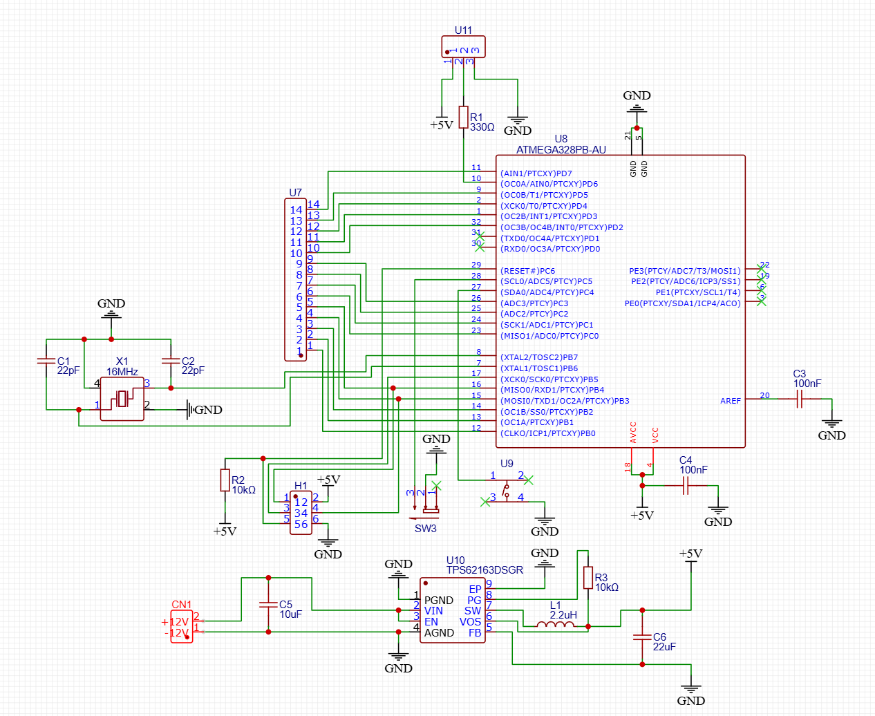
Schaltplan mit ATmega328PB und TPS62163DSGR
U11, R1 330Ω, U8 ATMEGA328PB-AU, GND, +5V, U7, C1 22pF, X1 16MHz, C2 22pF, GND, PE3(PTCY)/ADC7/T3/MOSI1, PE2(PTCY)/ADC6/ICP3/SSI, PE1(PTCY)/SCK/T1/4, PE0(PTCY)/SDA0/ICP4/ACO, PC2(PTCY) 24, PC1(PTCY) 23, PC0(PTCY) 22, PB7(XTAL2/TOSC2) 8, PB5(XTAL1/TOSC1) 17, PB4(MISO/RXD1/PTCY) 16, PB3(MOSI0/TXD0/OC2A/PTCY) 15, PB2(OC2B/SS0/PTCY) 14, PB1(OC1A/PTCY) 13, PB0(CLKO/ICP1/PTCY) 12, R2 10kΩ, H1, +5V, U9, SW3, C4 100nF, AREF, VCC, C3 100nF, CN1, 12V, U10 TPS62163DSGR, EP, PG, VIN, SW,
in „LED Zuleitungen reduzieren.“ · Mikrocontroller und Digitale Elektronik · · Schaltpläne
-
Datei
OSZI.asm
-> 177,2kS/s ; *100=4 => 16 x 13 Takte = 208 Takte -> 88,6kS/s ; 101=5 => 32 x 13 Takte = 416 Takte -> 44,3kS/s ; 110=6 => 64 x 13 Takte = 832 Takte -> 22,1kS/s ; 111=7 => 128 x 13 Takte = 1664 Takte -> 11,1kS/s sbi ADCSRA, ADEN
in „einfaches DIGITAL- Oszilloskop (800 Datenpunkte) Assembler“ · Projekte & Code ·
-
Datei
main.c
Date : 24.01.2004 Author : Freeware, for non-commercial use only Company : Comments: Chip type : ATmega128 Program type : Application Clock frequency : 16,000000 MHz Memory model : Small External SRAM size : 0 Data Stack size : 1024 *********************************************/ #include <mega128.h>
in „Problem mit Atmega 128“ · Mikrocontroller und Digitale Elektronik ·
-
PDF
AVR911.pdf
h Help information (overrides all other settings). -? Same as –h Some examples follows: avrosp –dATmega128 –pf –vf –ifprogram.hex –e The above example will first erase the entire memory contents and then program and verify the data contained in program.hex to an attached Atmega128 device. avrosp –dATmega32 –re –oedump.hex –ae0,ff –cCOM2 The above example will read the first 256 bytes of the Atmega32’s EEPROM memory to the file dump.hex. Only COM2 will be used. avrosp –dATmega64 –O#a0 –Se0 –lc0 4 AVR911 2568A-AVR-07/04 AVR911 The above example will write the custom oscillator calibration value
in „AVR911: Das Ende aller Leiden?“ · Mikrocontroller und Digitale Elektronik ·
-
 Bild
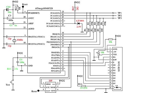
Schaltplan mit ATmega8/168/328 und LCD Display
VCC Reset 10k ATmega8/168/328 PC6(RESET) 23 PC0(ADC0) 24 PC1(ADC2) 25 PC2(ADC3) 26 PC3(ADC4/SDA) 27 PC4(ADC5/SCL) 28 PC5 2.5V LT1004 R1 680 R2 470k R3 680 R4 470k R5 680 TP1 TP2 TP3 C10 10u C3 100n C1 In 22p 8MHz 22p PB0
in „problems with resistor messuaring“ · Mikrocontroller und Digitale Elektronik · · Schaltpläne
-
 Bild
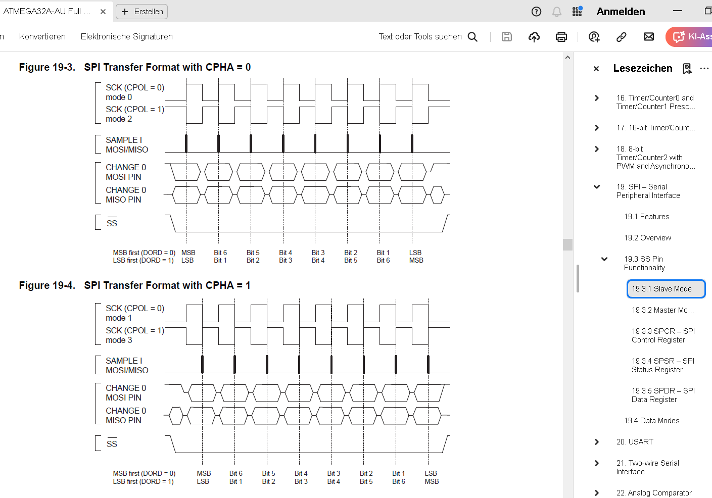
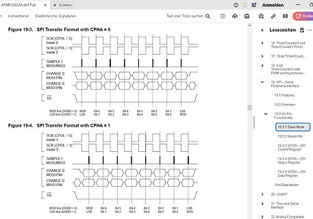
Zeitdiagramme für SPI-Übertragungsformate
ATMEGA32A-AU Full... Anmelden Figure 19-3. SPI Transfer Format with CPHA = 0 SCK (CPOL = 0) mode SCK (CPOL = 1) mode 2 SAMPLE I MOSI/MISO CHANGE 0 MOSI PIN CHANGE 0 MISO PIN SS MSB first (DORD = 0) LSB first
in „25LC512 SPI EEPROM seltsames Verhalten / defekt?“ · Mikrocontroller und Digitale Elektronik · · Screenshots
-
PDF
Schaltung_OLED_EA_W204.pdf
Schaltung mit OLED 4x20 EA W204-XLG 7805 IC2 +5V 10µ 10µ OLED 4x20 1 D W 16 s D S / 0 1 2 3 4 5 6 7 V V R R E D D D D D D D D Programmieradapter 1 5 2 2 2 2 2 2 2 2 2 1 1 1 1 1 e 5 4 3 2 1 0 ) ) ) ) ) ) ) ) a C C C C C C N F E C B B B B B r ( ( ( ( ( ( ( R V ( ( ( ( ( m ( ( r ATmega8-16 ) IC1) ) ) r 6 0 1 2 3 4 C D 6 7 5 6 7 0 2 C D D D D D C N B P P DPD P P S P k3 ( ( ( ( ( ( ( ( P( 0 1 2 3 4 R 1 R 1 2 3 4 5 6 7 8 9 1 1 1 1 1 100nF Bernhard.Erfurt@gmx.de Version 1 11/2011
in „DISPLAY OLED EAW204 4-Bit Modus Initialisierung Assembler ATmega8“ · Projekte & Code ·
-
PDF
SCHALTPLAN_1-WIRE.pdf
Schaltung 1-WIRE IC25 +5V 10µ 10µ OLED 4x20 1 D / 16 V V R R E D D D D D D D D5 6 7 GND 2 3 DS18s20 S B Programmieradapter k 1 5 2 2 2 2 2 2 2 2 2 2 1 1 1 1 1 r ) ) ) ) ) ) ) ) ) ) ) ) ) ) a C C C C C C 1 0 N F E C B B B B B - ( ( ( ( ( ( G R V ( ( ( ( ( m ( ( ( a ATmega8-16 IC1 r ) ) ) ) ) ) ) D ) 7 5 6 7 0 2 C D D D D D C3 4 C N B B D D D B E P ( ( ( ( ( ( ( ( P( ( ( ( ( ( E 1 R 1 2 3 4 5 6 7 8 9 1 1 1 1 1 R 100nF 22 22 1MHz bei Bedarf bei Bedarf TRIGGER-AUSGÄNGE
in „DS1820 DS18s20 Digital Thermometer 1-wire Beispiele ATmega8 Assembler“ · Projekte & Code ·
-
PDF
SCHALTPLAN_DCF77_MINI_2012.pdf
3 2 1 0 D F) C 5 4 3 2 1 d C C C C C C N E C B B B B B r ( ( ( ( ( ( ( R V ( ( ( ( ( m ( ( IC1 r ATmega8-16 ) ) ) ) ) ) ) P 6 0 1 2 3 4 C D 6 7 5 6 7 0 T N C D D D D D C N B P P DPD P P S P k ( ( ( ( ( ( ( ( P( 0 1 2 3 4 R 1 1 2 3 4 5 6 7 8 9 1 1 1 1 1 100n 100nF 16MHz l a 7 i F s D g a R l g R ü i R
in „DCF / DCF77 UHR - LCD LED Samplingverfahren ATmega8 ASSEMBLER“ · Projekte & Code ·
-
PDF
STK300_Stromlaufplan.pdf
17 8 A1 D1 13 AD2 D3 Q3 A2 D2 ) ) ) ) ) L ) ) ) ) ) ) ) ) D R AD3 5 D4 Q4 16 7 A3 D3 15 ( ( ( ( ( A 1 1 1 1 1 1 ( ( R W AD4 6 D5 Q5 15 6 A4 D4 16 49 PA2 (A2) 3 4 5 6 7 ( ( ( ( ( ( 1 0 PD7(T2) 32 AD5 7 14 5 17 P P P P P C C C C C C P P 8 D6 Q6 13 4 A5 D5 18 50 P P P P P P 31 AD6
-
PDF
RF_Relay_Box.pdf
/PCINT6) 30 DIP_1 Hole M3 Hole M3 PD6 (OC2B/ICP/PCINT30) PA7 (ADC7/PCINT7) Hole M3 Hole M3 Relay_2 16 PD7 (OC2A/PCINT31) AREF 29 DipSwitch 8Pole SMD 3.3V 17 VCC GND 28 GND GND 18 GND AVCC 27 3.3V C9 Signal_S4 19 26 100nF Signal_S3 20 PC0 (SCL/PCINT16) PC7 (TOSC2/PCINT23) 25 0603 Signal_S2 21 PC1 (SDA
in „ATmega 164P USART funktioniert nur mit beschaltung auf PB7“ · Mikrocontroller und Digitale Elektronik ·
-
Datei
NanoEveryRegister.h
/ Slewrate Bit }; constexpr Offset addrOffset; struct Address // base addresses of registers { uint16_t vport; uint16_t port; uint8_t pinCtrl; uint8_t mask; }; // The index is always the Arduino pin number. constexpr Address baseAddr[] { // | VPORT | PORT | PINn | BIT | // | Base | Base | CTRL | MASK
in „Wie Klassen-Template Objekte in einem Array nutzen (non Template, constexpr, inline)“ · Mikrocontroller und Digitale Elektronik ·
-
PDF
STK300S.pdf
17 8 A1 D1 13 AD2 D3 Q3 A2 D2 ) ) ) ) ) L ) ) ) ) ) ) ) ) D R AD3 5 D4 Q4 16 7 A3 D3 15 ( ( ( ( ( A 1 1 1 1 1 1 ( ( R W AD4 6 D5 Q5 15 6 A4 D4 16 49 PA2 (A2) 3 4 5 6 7 ( ( ( ( ( ( 1 0 PD7(T2) 32 AD5 7 14 5 17 P P P P P C C C C C C P P 8 D6 Q6 13 4 A5 D5 18 50 P P P P P P 31 AD6
in „Kanda AVR Starterboard und noch keine Ahnung“ · Mikrocontroller und Digitale Elektronik ·
-
Datei
teststk_mega16.c
Driver for SHARP LM24014 LC-Display based on TOSHIBA T6963C LCD Controller # // # Designed for ATMEL ATMega16 and compatible µ-controllers # // # # // # Thomas Hohlbein, September 2006, Berlin, Germany # // # http://www.sound-inside.de, testicals@gmx.de # // # # // #######################################
in „LCD an T6963C und ATMega323“ · Mikrocontroller und Digitale Elektronik ·
-
Datei
Temp.asm
* ; mit diesem Programm kann man ein Signal aufzeichnen und ; über RS232 an den PC senden ; Beim atmega8 wird das Signal an ICP1 (PIN 14) angelegt ; Die gemessenen Pulsbreiten werden im SRAM gespeichert und ; auf Knopfdruck an den PC gesendet ; Taster an PB5, LED an PD2 zur Statusanzeige, LED an PD3
in „wer hilft mir, den fehler zu finden? atmega8“ · Mikrocontroller und Digitale Elektronik ·
-
Datei
ADC_USART_Read_adc.c
+++++++++++++++++++++++++++++++++++++++++++++++++++++++ 8-Bit-Analog-Digital-Converter mit ATMEL ATmega8 to STK500 board, output on (PortB) --> LEDs Description: The ADC converts an analog input voltage to a 10-bit digital value through successive approximation. The minimum value represents GND and the
in „warnung:"[variable]may be used uninizialized"“ · Mikrocontroller und Digitale Elektronik ·
-
PDF
rp2.pdf
L30 3.3V 5 1 AVCC Vcc Vin FB 47 L31 Vcc LM2574 7 1 Out 470u C30 ON/OFF PGND SGND 1 D30 3 2 3 4 2 C16 C17 22u R 2 D31 C31 C1 P6SMB18A 2 1N5818 220u 10u 10u 100n 2 Vcc K 2 K 3 K 4 1 Q5 2 1 2 1 R R R S Q4 IRLML2402 Vcc CONN2 S 10 9 IRLML2402 0 1 1 FF K K K K 9 Dauerplus 8 Q1 Q2 Vcc S1 0 0 0 0 8 1 8 IRLML2402
in „Wecker mit MP3 (vs1011) und SD-Card“ · Mikrocontroller und Digitale Elektronik ·
-
Datei
PWM_PA0-16-3.9khz.asm
;pwm an atmega16/32 für 2 khz (3,906) khz ;bei 4mhz taktfrequenz ;mit timer0 im fast pwm mode, 8 bit aufloesung ;pwm-signal liegt auf pb3 oc0 .include "m16def.inc" ;.def v_panel = r14 ;Messwert PV-Spannung PA0 .def
in „Hilfe Ladereglung Atmega16 Assembler“ · Mikrocontroller und Digitale Elektronik ·
-
Datei
PWM_PA0-Uvergl.-Einfach-15kHZ.asm
;ausgangsspannungsregelung nach stepdown ;pwm an atmega16 für 15 khz ;bei 4mhz taktfrequenz ;mit timer0 im fast pwm mode, 8 bit aufloesung ;pwm-signal liegt auf pb3 oc0 ;adc aufruf mittels rcall ;werner,24.2.12 .include "m16def.inc" .def v_akku = r22 ;Messwert Akku-Spannung PA0 .def temp1 = r16 ;temporäre Variable .def temp2 = r17 ;temporäre Variable .def v_akkupwm = r19 ;ermittellter Vorladewert ocr0 .def v_store = r20 ;gespeicherte Wunschspannung am PWM-Ausgang .org 0x000 rjmp RESET ;External
in „Hilfe Ladereglung Atmega16 Assembler“ · Mikrocontroller und Digitale Elektronik ·
-
Datei
timer1.c
/ date: 2013-12-15 // -------------------------------------------------------- // Bsp. für MCU = atmega32 // die notwendigen und benötigten // avr gcc Includefiles müssen noch geladen werden. // -------------------------------------------------------- // -------------------------------------------------------- // 16-Bit Timer - Timer1 // -------------------------------------------------------- #define T1_FREQUENCE 1000UL // 1000 Hz entspricht 1ms // -------------------------------------------------------- // 16-
in „Bits im Timer-Register durch Präprozessor / Compiler ausrechnen“ · Mikrocontroller und Digitale Elektronik ·
-
Datei
16ner.txt
Version : Date : 13.2.2006 Author : Winfried Jaeckel Company : Deviltronic Comments: Chip type : ATmega16 Program type : Application Clock frequency : 16,000000 MHz Memory model : Small External SRAM size : 0 Data Stack size : 256 *****************************************************/ #include <mega16
in „I/O Ports ATmega16“ · Mikrocontroller und Digitale Elektronik ·
-
PDF
AVR-Board_neutral.pdf
Funktionen-Auswahl S2 Pin Port ------------ S1 S3 RS PB0 EN PB1 D4 PB4 D5 PB5 LCD-DISPLAY 2x 16 Zeichen D6 PB6 D7 PB7 + - V 5 E S / N 0 1 2 3 4 5 6 7 E E S4 0 + V R R E D D D D D D D D L L S1 PB2 +5V S2 PB3 R16 R17 S3 PD3 (INT1) S6 ADUM1250BRZ KIMaip R11 S4 PD2 (INT2) VDD1 VDD2 In/Out1 KNX-GND
in „[V] AVR-Module mit ATMEGA644 in Hutschinengehäuse“ · Markt ·
-
PDF
550-0028_ProMiniClone_Sch_V4.pdf
PB0 6 A2 RESET 18 AVCC 7 A1 CON6 ADC7 22 8 A0 C16 19 RFC2 0u1 21 ADC6 28 AD5/SCL 9 SCK 10uH GND GND ADC5/PC5 10 MISO ADC4/PC4 27 AD4/SDA 11 MOSI GND ADC3/PC3 26 AD3 12 D10 25 AD2 6 ADC2/PC2 24 AD1 CON12 VCC VCC ADC1/PC1 C15 C17 4 VCC ADC0/PC0 23 AD0
in „ATMEGA328P auf eigenen Board“ · Mikrocontroller und Digitale Elektronik ·
-
PDF
MK_3_02.sch.pdf
SWRXTX R3D1 (PCINT19/TMS)PC3 22 GND (PCINT18/TCK)PC2 21 R15 LED6 (PCINT17/SDA)PC1 20 L10 P on (PCINT16/SCL)PC0 19 L9 Q S 100 2 (PCINT31/OC2A)PD7 16 L4 A K 1 (PCINT30/OC2B/ICP)PD6 15 L3 S Q3 1 R (PCINT29/OC1A)PD5 14 L2 B BSS123 (PCINT28/OC1B)PD4 13 6 0 C 39 GND (PCINT27/INT1)PD3 12 R 1 4u7 C 28 GND (PCINT26
in „ATmega 644 Ports Parallel geschaltet MK3 Programmer“ · Mikrocontroller und Digitale Elektronik ·
-
Datei
main.asm
40 e1 ldi r20, 0x10 ; 16 push x4 ;[9] == leap 790c: 5f 93 push r21 in x1, USBIN ;[11] <-- sample bit 0 790e: 00 b3 in r16, 0x10 ; 16 andi x1, USBMASK ;[12] 7910: 05 70 andi r16, 0x05 ; 5 bst x1, USBMINUS ;[13] 7912: 00 fb bst
in „ATMEGA32 Minimum System Board“ · Mikrocontroller und Digitale Elektronik ·
-
PDF
AVR-Tutorial_-_Mikrocontroller.net.pdf
Mikrocontroller werden als erstes an der Bit-Zahl des internen Datenbusses unterschieden: 4bit, 8bit, 16bit und 32bit. Diese Bit-Zahl kann man als die Länge der Daten interpretieren, die der Controller in einem Befehl verarbeiten kann. Die größte in 8 Bit (= 1 Byte) darstellbare Zahl ist die 255, somit
-
PDF
tut_test.pdf
Mikrocontroller werden als erstes an der Bit-Zahl des internen Datenbusses unterschieden: 4bit, 8bit, 16bit und 32bit. Diese Bit-Zahl kann man als die Länge der Daten interpretieren, die der Controller in einem Befehl verarbeiten kann. Die größte in 8 Bit (= 1 Byte) darstellbare Zahl ist die 255, somit
-
PDF
DOG_readme.pdf
ASCII-Zeichen reduziert. Dadurch findet neben dem Normalfont (6x8) auch der doppelt breite Bigfont (12x16) Platz im Eeprom. Fontskalierung, Proportionalschriften, Zeilenumbruch etc. sind in meinen Projekten nicht gefragt. Textmodus: Normal- und Big-Font Als einzige Besonderheit bei den beiden Fonts (die
in „Grafikausgabe auf dem LCD-Grafikmodul DOG 128x64 für M88 in C“ · Projekte & Code ·
-
 Bild
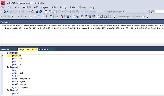
Screenshot einer Assembler-Programmierung in Microchip Studio
R23 = 0x00 R24 = 0x00 R25 = 0x00 R26 = 0x00 R27 = 0x00 R28 = 0x00 R29 = 0x00 R30 = 0x00 R31 = 0x00 ATmega8 Simulator main.asm lcd4puts.inc lcd4puts: push r0 push r16 push z1 push zh lcd4puts1: lpm adiw z1,1 tst r0 breq lcd4puts2 mov r16,r0 rcall lcd4put rjmp lcd4puts1 lcd4puts2: pop zh
in „Problem beim Debug im Simulator im Microchip Studio 7.0“ · Mikrocontroller und Digitale Elektronik · · Screenshots
-
Datei
uart.c
www.hpinfotech.com Project : Version : Date : 13.05.2008 Author : Leon Company : - Comments: Chip type : ATmega32 Program type : Application Clock frequency : 13,000000 MHz Memory model : Small External SRAM size : 0 Data Stack size : 512 *****************************************************/ #include <mega32
in „Problemm mit dem UART atmega 32“ · Mikrocontroller und Digitale Elektronik ·
-
Datei
uart.c
//UBRRL = (uint8_t)UART_BAUD_RATE; UBRRH = 00; UBRRL = 12; /* alternativ bei der avr-libc "direkt 16bit" : */ //UBRR = UART_UBRR_CALC(UART_BAUD_RATE,F_CPU); UCSRA = 0x02; UCSRB |= ( 1 << TXEN ); // UART TX einschalten UCSRB |= ( 1 << RXEN ); // UART RX einschalten UCSRC |= ( 1 << URSEL )|( 3<<UCSZ0
in „Zähler & Interrupt auslösen ATmega32“ · Mikrocontroller und Digitale Elektronik ·
-
Datei
485test.c
485test // Funktion : 485 Schnittstelle (USART0) soll Zeichen senden // Schaltung : // Prozessor : ATmega128 auf SAVY128 von chip45.com // Sprache : C // Datum : 16.08.2006 // Version : 1.0 // Autor : Ederer Christoph // --------------------------------------------------------------------------- #include
in „USART Gehversuche und "syntax error before "volatile""“ · Mikrocontroller und Digitale Elektronik ·
-
Datei
I2C_LCD_2.bas
BASCOM-AVR (Vers. 2.0.7.7) 'Hardware : Versuchsplatine LCD 8x2 (Holz) u. Modul von Pollin 'Chip type : ATMega48V (14%) 'Programm : I2C_LCD_2 > Zeichen an LCD '************************************************************************ $regfile = "m48def.dat" $crystal = 4000000 'Quarz (111101) DivideClock = disabled
in „LCD 20x4 I2C Bascom“ · Mikrocontroller und Digitale Elektronik ·
-
Datei
I2C_LCD_4.bas
BASCOM-AVR (Vers. 2.0.7.7) 'Hardware : Versuchsplatine LCD 8x2 (Holz) u. I2C-Modul (SMD) 'Chip type : ATMega48V (14%) 'Programm : I2C_LCD_2 > Zeichen an LCD '*********************************************************************** $regfile = "m48def.dat" $crystal = 4000000 'Quarz (111101) DivideClock = disabled
in „LCD 20x4 I2C Bascom“ · Mikrocontroller und Digitale Elektronik ·
-
PDF
LCD_Controller_320x240.pdf
Mittelpunkt 160,120 und dem Radius 15, gefüllt mit der dunkelsten Graustufe und einem etwas helleren Rand 16 170 2 16 1 8 0 1 2 4 8 16 32 64 128 zeichnet ein 8x8 Pixel großes Bild mit den Daten 1, 2, 4, 8, 16, 32, 64, 128 (=schräge Linie) an die Position 16, 16 16 170 4 16 2 8 1 0 3 0 12 0 48 0 192 zeichnet
in „Grafikfähiger LCD Controller für 320x240 LCD mit D-RAM“ · Projekte & Code ·
-
Datei
main.c
uint16_t *isr_ptr_time = pwm_timing; uint16_t *main_ptr_time = pwm_timing_tmp; uint16_t *isr_ptr_mask = pwm_mask; // Bitmasken fuer PWM-Kanäle uint16_t *main_ptr_mask = pwm_mask_tmp; // ändern uint16_t oder
in „Soft-PWM Version 3: Probleme beim Anpassen des Programms“ · Mikrocontroller und Digitale Elektronik ·