-
PDF
panasonic-lithium-br2330-br3032.pdf
capacity (mAh) 500 Continuousstandardload(mA) 0.03 Continuousstandardload(mA) 0.03 Operating temperature (C) Operating temperature (C) -30 ~ +80 -30 ~ +80 ■ Temperature Characteristics ■ Temperature Characteristics Load: 100KΩ (29µA) Load 3.0 20˚C 60˚C 3.0 ) V e -10˚C e a2.5 a2.5 o o V V 2.0 2.0 ~ ~ 0 2000
in „Gesucht: Extra Long Life Knopfbatterien“ · Mikrocontroller und Digitale Elektronik ·
-
PDF
MPT2P50E.pdf
recommended choices for future use and best overall value. ⊕ Semiconductor Components Industries, LLC, 2000 1 Publication Order Number: November, 2000 – Rev. 3 MTP2P50E/D MTP2P50E ELECTRICAL CHARACTERISTICS (TJ= 25⋅C unless otherwise noted) Characteristic Symbol Min Typ Max Unit OFF CHARACTERISTICS Drain–Source
in „Ersatztypen für Diode“ · Mikrocontroller und Digitale Elektronik ·
-
PDF
Haartrockner.pdf
Sicherheit“ bei Anwendung im Bad vorhanden. Anh. 4 Abb. 15 Haartrockner USA: ALCI Typ 166 u i u W e ge e c l e un b e r e g i b e n a o d d r n e m d e a r d e g n N e V h E e e c S t t n G m n b l s a ä e h c e u e n e a e h b t w z h d d t N t c F u N e d c n n w e t c e h , e r r h l . a u r d r r . s c a m t m s n n s m r B a u d S n r e f e d m d n z e , e e c n m t m a r u c V d r n t a a u u h g r v r n e n nu o d e e e m m r m d b H d T ü b e d t n u t e a n b a e a n n e e d e B c s ö g r c a
in „wir schmeißen mal einen Föhn in die Badewanne.“ · Offtopic ·
-
Bild
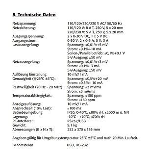
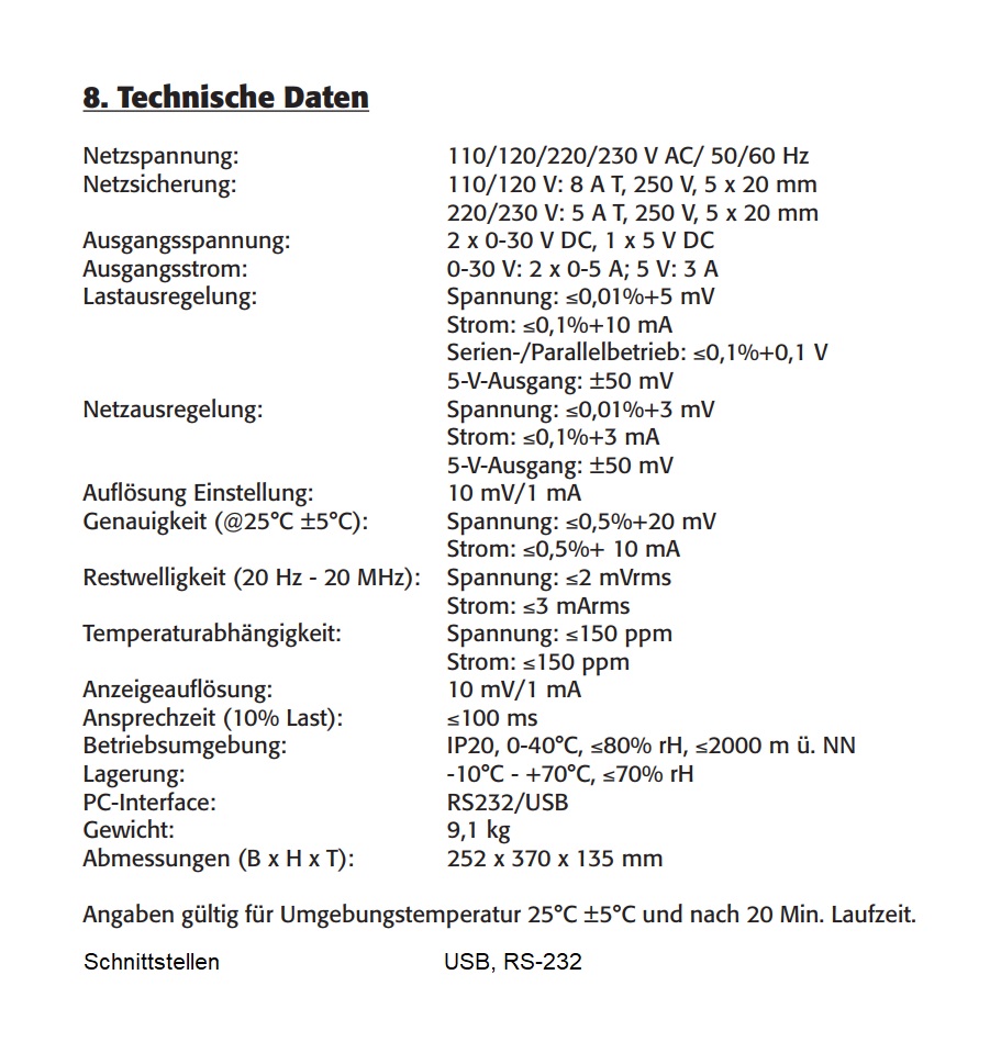
Technische Daten eines Netzteils
0,01%+3 mV Strom: ≤0,1%+3 mA 5-V-Ausgang: ±50 mV Auflösung Einstellung: 10 mV/1 mA Genauigkeit (@25°C ±5°C): Spannung: ≤0,5%+20 mV Strom: ≤0,5%+ 10 mA Restwelligkeit (20 Hz - 20 MHz): Spannung: ≤2 mVrms Strom: ≤3 mArms Temperaturabhängigkeit: Spannung: ≤150 ppm Strom: ≤150 ppm Anzeigeauflösung: 10 mV/1 mA Ansprechzeit (10% Last): ≤100 ms Betriebsumgebung: IP20, 0-40°C, ≤80% rH, ≤2000 m ü. NN Lagerung: -10°C - +70°C, ≤70% rH PC-Interface: RS232/USB Gewicht: 9,1 kg Abmessungen (B x H x T): 252 x 370 x 135 mm Angaben gültig für Umgebungstemperatur 25°C ±5°C und nach
in „[V] Lineares Labornetzteil KA3305P, 2x 0-30V/5A, 1x 5V/3A“ · Markt · · Screenshots
-
Datei
main.c
BAUD_VAL ((F_CPU / 16 / BAUD) - 1) char output[100]; uint8_t val; int main(void){ initUart(); i2c_init(); sei(); _delay_ms(2000); //Warten um auf Serial Programm zu verbinden writeEEPROM(1, 0x44); //0x44 an EEPROM Adresse 1 schreiben _delay_ms(1000); //Kurzes Delay dazwischen val = readEEPROM(1);
in „EEPROM Chip will nicht so wie ich“ · Mikrocontroller und Digitale Elektronik ·
-
Datei
main.c
kein uart uart1_puts("Aktiviert!\r"); while(1) { if (timer_counter > 2000) // Alle 5ms Slave abfragen { byte1=0; byte2=0; byte3=0; PORTD ^= (1<<PD5); if(!(i2c_start(SLAVE_ADRESSE+I2C_WRITE))) //Slave bereit zum lesen der Taster? { i2c_write(0x00); //Buffer Startadresse zum Auslesen i2c_rep_start(SLAVE_ADRESSE+I2C_READ); //Lesen beginnen byte1= i2c_readAck(); // Bytes lesen... byte2= i2c_readAck(); byte3= i2c_readNak(); i2c_stop(); // Zugriff beenden uart1_puti(byte1); uart1_puts("
in „I2C Kommunikation mit Quarz nicht möglich“ · Mikrocontroller und Digitale Elektronik ·
-
Datei
fritzbox_7590_log.txt
0e B . . . pagesize = 00000800 no_of_pages_in_block = 00000040 * * * * * Detected PXB4583el V1.2-2000 .[piglet] Suceeded (AVM) EVA Revision: 1.3578 (C) Copyright 2005 AVM Date: Nov 27 2018 Time: 13:38:30 (2) 3 0x0-0x46409 [NAND:] 512MB MACRONIX 2048 Pagesize 128k Blocksize 4096 Blocks HW [SYSTEM:] GRX5
in „FritzBox 7590 Boot Loop“ · Mikrocontroller und Digitale Elektronik ·
-
PDF
Spannungsregler_XC6902_negative_LDO_200mA.pdf
CHARACTERISTICS (Continued) (3) Dropout Voltage vs. Output Current XC6902N331 XC6902N501 CIN 1.0μF(ceramLc), C = 1.0μF(ceramic) CIN 1.0μF(ceramiL), C = 1.0μF(ceramic) 2000 2000 Ta=-40℃ Ta=-40℃ V 1800 ] 1800 m 1600 Ta=25℃ V 1600 Ta=25℃ i Ta=85℃ [ Ta=85℃ V 1400 d 1400 e 1200 : 1200 a g l 1000 l 1000 V 800 o 800
in „Geregelte negative Spannung mit LM2664 und LP2980 - geht das überhaupt?“ · Analoge Elektronik und Schaltungstechnik ·
-
Bild
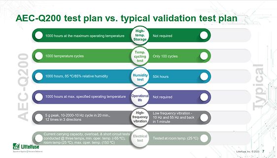
Vergleich AEC-Q200 Testplan vs. typischer Validierungsplan
required Temp. cycling test: 1000 temperature cycles | Only 100 cycles Humidity test: 1000 hours, 85 °C/85% relative humidity | 504 hours Operational life: 1000 hours at max. specified operating temperature | Not required High-frequency vibration: 5 g peak, 10-2000-10 Hz cycle in 20 min., 12 times in 3
in „News-Allerlei: X86-ISA-Erweiterung, Realtime-Linux und anderes mehr“ · Mikrocontroller und Digitale Elektronik · · Diagramme
-
PDF
Schematics.pdf
2 1 B B D1 R9 D1N4148 2200k R11 C1 1000k U1 3 + 7 5 V V+ + V1 100n OS2 6 5V OS1 2 - V- 1 C4 - 4 100n V3 uA741 0.1V + - R4 D2 2200k D1N4148 1000k R5 R7 2200k C5 10u 20k R6 10k C6 22p C3 10u 0 A A OrCAD, Inc. Page Size: A 13221 S.W. 68th Parkway, Suite 200 Beaverton, OR 97223 (503) 671-9500 (800) 671-9505 Revision: - January 1, 2000 Page 1 of 1 2 1
in „Gitarrenvorverstärker für CODEC. -> Stimmt die Schaltung?“ · Analoge Elektronik und Schaltungstechnik ·
-
Datei
Attiny.txt
Uhfuse:w:0xdf:m -Ulfuse:w:0xe2:m avrdude: Version 6.3-20190619 Copyright (c) 2000-2005 Brian Dean, http://www.bdmicro.com/ Copyright (c) 2007-2014 Joerg Wunsch System wide configuration file is "C:\Program Files (x86)\Arduino\hardware\tools\avr/etc/avrdude.conf" Using Port :
in „Projekt fertiggestellt: MP3 Player für Kinder auf ATTiny-Basis“ · Projekte & Code ·
-
PDF
Refillanleitung_Deutsch.pdf
C Deskjet 843 C Deskjet 995 C Officejet R 60 PSC 950 Deskjet 1180 CXI Deskjet 845 C Digiprinter DP 100 Officejet R 65 PSC 950 SE Deskjet 1220 C Deskjet 845 CVR Digistation 2000 Officejet R 80 PSC 950 VR Deskjet 1220 C/PS Deskjet 870 CXI Digistation DS 2000 Officejet R 80 XI PSC 950 XI Deskjet 1220 CSE Deskjet 880C Digistation DS 2000 Office Officejet T 45 Deskjet 1220 CXI Deskjet 882 C Digital Copier 310 Officejet
in „Patrone HP45 HP15 HP78 von HP959C Erfahrung Refill“ · PC Hard- und Software ·
-
PDF
LHC1-22XX_Super_LEDs.pdf
designates ANSI color point (e.g. 30 for 3000K) C C — designates minimum CRI level (e.g. 80 for minimum 80CRI) D D E E — designates product configuration (e.g. 1203 for the 1000-2000 lumen package) L 2 C A – B B C C D D E E F F G G G (New Part Number
in „Entladeformel einer Spule“ · Analoge Elektronik und Schaltungstechnik ·
-
Datei
01_bme_280_a.ino
BME280 Breakout board – --> http://www.adafruit.com/products/2650 This sketch only supports the I2C bus for connection. ***************************************************************************/ #include <Wire.h> #include "cactus_io_BME280_I2C.h" BME280_I2C bme(0x76); // I2C using address 0x76 void
in „Arduino SD und BME280“ · Mikrocontroller und Digitale Elektronik ·
-
PDF
Vishay_Z-Foil.pdf
1 W at +125°C (see table 2) • Resistance tolerance: to ±0.005% (50 ppm) • Load life stability: ±0.005% at 70°C, 2000 h or ±0.015% at 70°C, 10000 h (see table 4) The stability of a resistor depends primarily on its
-
PDF
LM2937.pdf
−40˚C ≤ TJ≤ 125˚C LM2937ES-5.0 LM2937ES-8.0 LM2937ES-10 LM2937ES-12 LM2937ES-15 TS3B TO-263 LM2937ET-5.0 LM2937ET-8.0 LM2937ET-10 LM2937ET-12 LM2937ET-15 T03B TO-220 −40˚C ≤ TJ≤ 85˚C LM2937IMP-5.0 LM2937IMP
in „Minimale Hardware zum Auto CAN-Bus abhören“ · Mikrocontroller und Digitale Elektronik ·
-
Bild
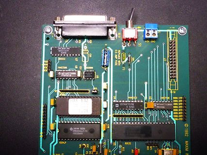
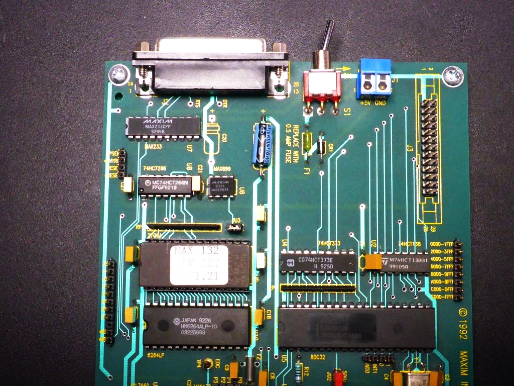
Bestückte grüne Leiterplatte mit integrierten Schaltkreisen
MAXIM MAX233C PP 9248 MAX233 74HC7266 U5 C3 MAX899 MC74HC7266N FFGP9219 MAX 132 74HCT373E 99105R 74HCT313 74HCT38B 0000-1FFF 2000-3FFF 4000-5FFF 6000-7FFF A000-BFFF C000-DFFF E000-FFFF JAPAN 9226 HMB264ALP-10 02252993 6264LP 80C32 1992 MAXIM
in „[V] MAX132 EVAL-KIT, 18-Bit-ADC“ · Markt · · Platinenfotos
-
Bild
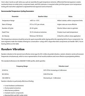
Text über Temperaturzyklen und Zufallsvibrationen
Temperature Cycling Parameters: Temperature Range: -40°C to +75°C Rate of Change: 5°C to 15°C per minute Number of Cycles: 20-30 cycles Dwell Time: 10-15 minutes at extremes Air Velocity: Minimum 750 ft/min Random Vibration Frequency Range: 20-80 Hz, 80-350 Hz, 350-2000 Hz Vibration Level: 0.01 G²/Hz increasing at 3 dB/octave, 0.04 G²/Hz flat, Decreasing at -3 dB/octave
in „Künstliche Alterung von Leiterplatten“ · Platinen · · Screenshots
-
PDF
SG3525ANG.pdf
Reference Output Current ref 50 mA Oscillator Charging Current 5.0 mA Power Dissipation P mW D TA = +25⋅C (Note 1) 1000 TC = +25⋅C (Note 2) 2000 Thermal Resistance, Junction−to−Air R▯JA 100 ⋅C/W Thermal Resistance, Junction−to−Case R▯JC 60 ⋅C/W Operating Junction Temperature T +150 ⋅C J Storage Temperature
in „Gegentaktwandler Überschwingen im Leerlauf“ · Analoge Elektronik und Schaltungstechnik ·
-
PDF
PS-ITG-3200-00-01.4.pdf
Specifications Typical Operating Circuit of Section 4.2, VDD = 2.5V, VLOGIC = 1.71V to VDD, T =25°C. A Parameter Conditions Min Typical Max Unit Note GYRO SENSITIVITY Full-Scale Range FS_SEL=3 ±2000 º/s 4 Gyro ADC Word Length 16 Bits 3 Sensitivity Scale Factor FS_SEL=3 14.375 LSB/(º/s) 3 Sensitivity
in „STK600 / Atmega 2560 per TWI mit ITG-3200 verbinden“ · Mikrocontroller und Digitale Elektronik ·
-
PDF
DSA0087142.pdf
Bouskoura, B=Amkor, N=UTAC,Y=CARSEM). 1-digitYear (4=2004). 2-digitWorkWeek(01- 52). P Y WW AI02442c Figure 3. 16-lead SOIC date and assembly site code Assembly site (99 = Muar). 1-digitYear (4 = 2004). 2-digit Work Week (01 - 52). PP Y WW AI02442d Figure 4. SOT date and part number code 3-digit Part
in „ST MOSFET Date Code lesen“ · Analoge Elektronik und Schaltungstechnik ·
-
PDF
Pi_Filter.pdf
C2 5.52p R2 32.45k R1 R3 L1 R4 4m 4m V1 0.02 10µ C1 C3 R5 2 SINE() 4.7µ 4.7µ AC 1 0 Rser=0.1 L2 L3 880p 880p .ac lin 2000 1 5e9 --- C:\Programme\LTC\SwCADIII\Pi Filter.asc --- V(n002) 10dB 0dB -10dB -20dB
-
PDF
HMOxxxx_Open_Source_Acknowledgement_en_01.pdf
Truta libpng versions 1.0.7, July 1, 2000, through 1.2.5 - October 3, 2002, are Copyright (c) 2000-2002 Glenn Randers-Pehrson, and are distributed according to the same dis- claimer and license as libpng-1.0.6 with the following individuals
in „Hameg/R&S HMO-Oszilloskope Open Source(?)“ · Mikrocontroller und Digitale Elektronik ·
-
Datei
Error_lib.txt
"c_Mittelwert_bestimmen_S2001ID_817a.obj", "c_Mittelwert_bestimmen_S2001IuA_817a.obj" LIB51 LIBRARY MANAGER V4.24 COPYRIGHT KEIL ELEKTRONIK GmbH 1987 - 2002 *** ERROR 225: ATTEMPT TO ADD DUPLICATE PUBLIC SYMBOL FILE: c_Mittelwert_bestimmen_S2001IuA_817a.obj MODULE: C_MITTELWERT_BESTIMMEN_S2001IUA_817A PUBLIC: S2000W1_Z "T_Projekt_817a.LIB" - 0 Error(s), 0 Warning(s).
in „Array mit Funktion aufrufen mituVision2“ · Mikrocontroller und Digitale Elektronik ·
-
PDF
maxell-lisocl2-batteries-catalog.pdf
ER18/50 ER17/50 ER6 ER6C ER17/33 ER3 ER3S Nominal Voltage (V) 3.6 3.6 3.6 3.6 3.6 3.6 3.6 Nominal Capacity (mAh) *1 3650 2750 2000 1800 1600 1100 790 Nominal Discharge Current (µA) 125 125 100 100 75 40 35 Operating Temperature
in „Ladestrom schädlich für Li-SOCl2-Primärzellen?“ · Analoge Elektronik und Schaltungstechnik ·
-
PDF
182853-da-01-en-kmi_151t_drehzahlmesser.pdf
CONDITIONS MIN. MAX. UNIT VCC DC supply voltage Tamb = −40 to +85 °C; RL= 115 − 16 V Tstg storage temperature −40 +150 °C Tamb ambient operating temperature −40 +85 °C Tsld soldering temperature t ≤ 10 s − 260 °C output short-circuit duration to GND continuous; note 1
in „Drehzahlmesser für Drehbank“ · Mikrocontroller und Digitale Elektronik ·
-
PDF
KMI_151T.pdf
CONDITIONS MIN. MAX. UNIT VCC DC supply voltage Tamb = −40 to +85 °C; RL= 115 − 16 V Tstg storage temperature −40 +150 °C Tamb ambient operating temperature −40 +85 °C Tsld soldering temperature t ≤ 10 s − 260 °C output short-circuit duration to GND continuous; note 1
in „Fragen zur Magnetkraft?“ · Mikrocontroller und Digitale Elektronik ·
-
PDF
kmi_151t.pdf
CONDITIONS MIN. MAX. UNIT VCC DC supply voltage Tamb = −40 to +85 °C; RL= 115 − 16 V Tstg storage temperature −40 +150 °C Tamb ambient operating temperature −40 +85 °C Tsld soldering temperature t ≤ 10 s − 260 °C output short-circuit duration to GND continuous; note 1
in „Signal am Zündkabel abgreifen ?!“ · Mikrocontroller und Digitale Elektronik ·
-
PDF
KMI15.pdf
CONDITIONS MIN. MAX. UNIT VCC DC supply voltage Tamb = −40 to +85 °C; RL= 115 − 16 V Tstg storage temperature −40 +150 °C Tamb ambient operating temperature −40 +85 °C Tsld soldering temperature t ≤ 10 s − 260 °C output short-circuit duration to GND continuous; note 1
in „KMI15/1 Drehzahlsensor reagiert nicht“ · Mikrocontroller und Digitale Elektronik ·
-
Datei
ulltoa_base10.h
progmem__)); #else extern const uint64_t ulltoa_pow10_table[]; #endif #ifdef __cplusplus } #endif /* C++ */ /* Just a C analogon of ulltoa_base10 to show the basic principle. */ extern char* ulltoa_base10_C (uint64_t x, char *buf); /* A simple but also typically veeery slooow C implementation. */ extern char* u64toa_base10_C (uint64_t x, char *buf); #endif /* ULLTOA_BASE10_H */
in „ItoA mit Uint64_t“ · Mikrocontroller und Digitale Elektronik ·
-
Bild
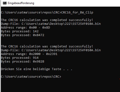
Windows-Kommandozeile mit CRC16-Berechnungsergebnissen
C:\Users\satma\source\repos\CRC>CRC16_for_BW_Clip The CRC16 calculation was completed successfully! Dump-File: C:\Users\satma\Desktop\222\SST25VF010A.bin Address range: 0x00 - 0x8D Bytes processed: 142 Bytes processed: 0x8472 The CRC16 calculation was completed successfully! Dump-File: C:\Users\satma\Desktop\222\SST25VF010A.bin Address range: 0x2000 - 0x2391 Bytes processed: 914 Bytes processed: 0x982B Drücken Sie eine beliebige Taste . . . C:\Users\satma\source\repos\CRC>
in „Reset BW Clip“ · Mikrocontroller und Digitale Elektronik · · Screenshots
-
PDF
Datasheet_IVT-S_V1.02.pdf
32.000 + 32.000 27 U3 measurement minimum V - 32.000 + 32.000 28 Temperature measurement maximum 1/10 °C - 500 + 2000 29 Temperature measurement minimum 1/10 °C - 500 + 2000 3.5.Firmware update To update the firmware, the IVT has an implemented bootloader. Firmware update can only be done by Isabellenhütte
in „Strommessung bis 60V“ · Analoge Elektronik und Schaltungstechnik ·
-
PDF
AVX_Ta-Caps_11903.pdf
products Style Case code No. of pieces Style Case code No. of pieces Style Case code No. of pieces A, B, C, D 3000 A 1500 A to H 1000 B, C, D 1250 TAP E, F, G 2500 TAP J to L 500 TAP H, J 2000 E, F 1000 M to R 100 G, H, J 750 K, L, M, N, P, R 1000 K, L, M, N, P, R 500 AMMO PACK DIMENSIONS GENERAL NOTES millimeters
in „Widerstände und Tantal-Elkos“ · Analoge Elektronik und Schaltungstechnik ·
-
Datei
main.c.txt
; DDRA &=~ (1<<PA7); PORTA = 0b11111111; DDRB = 0x00; //Alle B Pins = Eingänge DDRC = 0x00; //Alle C Pins = Eingänge DDRD = 0xE0; //Portleitung D.7 D.6 und D.5 als Ausgang PORTC = 0b11111111; //Ports auf Low schalten PORTA = 0x00; //Ports auf Low schalten PORTD = 0x00; //Ports auf LOW schalten piep(
in „Vorstellung und gleich eine Frage“ · Mikrocontroller und Digitale Elektronik ·
-
PDF
Bleifrei_Interview_d.pdf
weniger spürbar. MS – Welches Ersatzprodukt empfiehlt sich für Weil bleifreies Lot mindestens 30 °C höhere die Vorverzinnung der Beine? Schmelztemperaturen hat als Zinn-Blei, schleicht GG – Reinzinn wird sich etablieren, insbesondere, man permanent der Zerstörungsgrenze der seit man die Problematik
in „Umstellung auf bleifrei“ · Mikrocontroller und Digitale Elektronik ·
-
Datei
Differenzen.txt
658968 HostComm.dll Länge: 20480 <> 22016 HotKeys.exe Länge: 156160 <> 161280 httpd.dll Diffs: 73958 i2c_drv.dll Länge: 31744 <> 34304 IECEExt.dll Diffs: 17710 iepeers.dll Diffs: 40501 iesample.exe Diffs: 66830 ImageBuildInfo.txt Länge: 122 <> 147 imaging.dll Diffs: 191064 inetcpl.cpl Diffs: 25673 initobj.dat
in „Pollin - Receiver-Mainboard mit Twin DVB-[T,C] Tuner, NXP PNX8950EH“ · Mikrocontroller und Digitale Elektronik ·
-
Datei
functions.c
: TRISBbits.TRISB0 = 0; // Ausgang für LED TRISBbits.TRISB3 = 0; // Ausgang für RN171-Reset //Port C: TRISCbits.TRISC1 = 0; //Ausgang für RN171-GPIO6 TRISCbits.TRISC2 = 0; //Ausgang für RN171-AWAKE //Port G: TRISGbits.TRISG7 = 0; //Ausgang für RN171-GPIO5 TRISGbits.TRISG6 = 0; //Ausgang für RN171-GPIO5
in „RN171 + Mikrocontroller“ · Mikrocontroller und Digitale Elektronik ·
-
PDF
opa2134.pdf
PDIP Package V(ESD) Electrostatic discharge Human-body model (HBM), per ANSI/ESDA/JEDEC JS-001 (1) ±2000 V OPA2134 in SOIC Package (1) Human-body model (HBM), per ANSI/ESDA/JEDEC JS-001 ±2000 V(ESD) Electrostatic discharge Charged-device model (CDM), per JEDEC specification JESD22- V C101 (2) ±500 OPA4134 in SOIC Package (1) Human-body model (HBM), per ANSI/ESDA/JEDEC JS-001 ±2000 V(ESD) Electrostatic discharge Charged-device model (CDM), per JEDEC specification JESD22- V C101 (2) ±200 (1) JEDEC document JEP155 states that 500-V HBM allows safe manufacturing with a standard ESD
in „Unerwünschtes Rauschen bei Allpassfiltern“ · Analoge Elektronik und Schaltungstechnik ·
-
PDF
36ddedx.pdf
V 850 AC 36DX851F200AC2A 2000 BC 36DX202F200BC2A 2800 BC 36DX282F200BC2A 3400 CC 36DX342F200CC2A 7400 DF 36DX742F200DF2A 250 V AT +85 °C, SURGE = 300 V DC 500 AB 36DX501F250AB2A 10 000 DJ 36DX103F250DJ2A 350 DC AT +85 °C, SURGE = 400 V 3100 DF 36DX312F350DF2A 3300 DF 36DX332F350DF2A 5100 DJ 36DX512F350DJ2A 450 V AT +85 °C, SURGE = 525 V DC 230 AC 36Dx231F450AC2A 2000 DF 36DX202F450DF2A 3100 DJ 36DX312F450DJ2A 3500 DJ 36DX352F450DJ2A Statements about product lifetime are based on calculations and internal testing.
in „Unterschied Bauform "kleiner Elko" "großer Elko"“ · Analoge Elektronik und Schaltungstechnik ·
-
Datei
fft232slow.asm
Y+0], [Z+0] += [Y+0] movw CL, AL ;B = [Z+2] - [Y+2], [Z+2] += [Y+2] lddw D, Y+0 ; subw A, D ; addw C, D ; stw Z+, C ; lddw B, Z+0 ; movw CL, BL ; lddw D, Y+2 ; subw B, D ; addw C, D ; stw Z+, C ;/ movw T0L, ZL movw ZL, T14L ;C=cos(p), D=sin(p) addiw Z, t_cos_sin128*2 ; lpmw C, Z+ ; lpmw D, Z+ ;/ movw ZL, T0L FMULS16 A, C, T4, T2 ;[Y+0] = A * C + B * D FMULS16 B, D, T8, T6 ;[Y+2] = B * C - A * D addw T2, T6 ; adcw T4, T8 ; stw Y+, T4 ; FMULS16 B, C, T4, T2 ; FMULS16 A, D, T8, T6 ; subw T2, T6 ; sbcw T4, T8 ; stw Y+, T4
in „Schnelle FFT in Assembler“ · Digitale Signalverarbeitung / DSP / Machine Learning ·
-
Bild
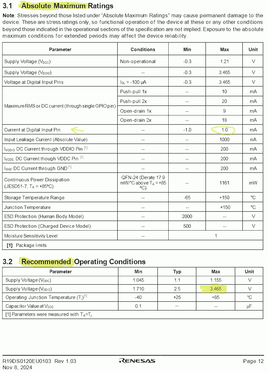
Tabellen mit absoluten Maximalbewertungen und empfohlenen Betriebsbedingungen
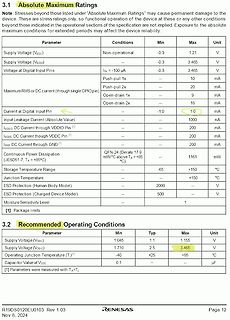
VDDC Pin 200 mA IOAND DC Current through GND 200 mA Continuous Power Dissipation (JESD51-7, TA = +85°C) mW/°C above TA = +85 °C 1161 mW Storage Temperature Range -65 +150 °C Junction Temperature +150 °C ESD Protection (Human Body Model) 2000 V ESD Protection (Charged Device Model) 500 V Moisture Sensitivity
in „Forge FPGA, kostenloser eval kit“ · FPGA, VHDL & Co. · · Screenshots
-
PDF
SchurterFusesResettable.pdf
at 23 °C/ Watts at 23 °C / Ampere bei 23 °C Ohms bei 23 °C Ohms bei 23 °C Sekunden bei 23 °C Watt bei 23 °C V A Hold Tripmin. max. R 1 max. PFRA.010.X 60 40 0.10 0.20 2.50 4.50 7.50 4.0 0.38 PFRA.017.X 60 40
in „Sicherung fliegt oft wegen GU10 Halogen-Birnen raus“ · Offtopic ·
-
PDF
ECO7213.pdf
the aid of Fig.5 we find the maximum input V.S.W.R (S) and the normalized correction capacitance (C ). T1nn C1 and C2 can be calculated: C 1n 2 C 1 ω × R and C2 = n × C 1 max 1 A practical problem that can arise is that the capacitor across the low-ohmic winding must have such a high value that it
in „Stackpole Ferrit Kerne für RF Verstärker“ · HF, Funk und Felder ·
-
Datei
EEVBLOG_CMU200.txt
8E1182008AE45EB2 42D23B964CE7C522 DE8BC25F5305D1EB 6E1701C72B5F9256 6B53740D41CF8780 DBBE31F8EAEB9C22 And the options installed are K21-K24, K27-K29, K42, K43, K53, K84, K85. Serial 837109/035 From another, Code: [Select] 917D1CFF38E8F2C1 AC15C4AFBA26733A D87CDA77974C9514 BE238053BEA30B16 75AE27EBF3F52E40 DFB718A6C9D85764 11B26D02CEE94BEA and options: K21-K24, K42, K43 and K45. Oh, and serial 103086. For those, like me, with little experience
in „Option B41 bei einer CMU200 nachrüsten.“ · HF, Funk und Felder ·
-
PDF
TLC5941.pdf
prevent electrostatic damage to the MOS gates. ORDERING INFORMATION TA PACKAGE (1) PART NUMBER –40°C to 85°C 28-pin HTSSOP PowerPAD™ TLC5941PWP –40°C to 85°C 32-pin 5 mm x 5 mm QFN TLC5941RHB –40°C to 85°C 28-pin PDIP TLC5941NT (1) For the most current package and ordering information, see the Package
in „AtMega 48 Timmer“ · Mikrocontroller und Digitale Elektronik ·
-
Bild
Datenblatt eines SCT036TS Stromwandlers
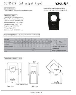
Material of core: Laminated silicon steel. Applicable standards: GB20840-2014. Operating temperature: -25 C ~+60 C. Storage temperature: -30 C ~+90 C. Frequency range: 50Hz-60Hz. Waterproof grade: IP00. Dielectric strength: 3.5KV 50Hz 1min. Electrical parameters: Rated input 100-600 A, Rated output 50-100 mA, Turns ratio 1:2000 bis 1:6000. Dimensions (in mm ±0.5): 66 x 92.5 x 48.5/41. www.poweruc.pl
in „AC Stromwandler 400A:50mA parallel ?“ · Analoge Elektronik und Schaltungstechnik · · Screenshots
-
Datei
main.c
) // Grundfunktion LED testen PB1_on(); WARTE_1S(); PB1_off(); WARTE_1S(); #endif /* DEBUG */ // I2C vorbereiten i2c_init(); test = i2c_start(DS1621_Write); I2CDEBUG(test, 1); test = i2c_write(0xEE); I2CDEBUG(test, 2); i2c_stop(); test = i2c_start(DS1621_Write); I2CDEBUG(test, 3); test = i2c_write(0xAA); I2CDEBUG(test, 4); i2c_stop(); warte(); while(1) { test = i2c_start(DS1621_Read); I2CDEBUG(test, 5); data = i2c_readAck(); TempH = data; data = i2c_readNak(); TempL = data; i2c_stop(); Temp = TempH; for (i=0;i<= 10;i++) {
in „Atmega8 - DS1621 auslesen ( über TWI[ i2c])“ · Mikrocontroller und Digitale Elektronik ·
-
Datei
main.c
MPU6050_RA_PWR_MGMT_1,0x00); } void MPU6050_Write_Reg(unsigned char reg,unsigned char data) { IdleI2C1(); StartI2C1(); IdleI2C1(); WriteI2C1(MPU6050_ADDRESS); IdleI2C1(); WriteI2C1(reg); IdleI2C1(); WriteI2C1(data); IdleI2C1(); StopI2C1(); } unsigned char MPU6050_Read_Reg(unsigned char reg) { unsigned char read; StartI2C1(); IdleI2C1(); WriteI2C1(MPU6050_ADDRESS); // Write WriteI2C1(reg); StartI2C1(); WriteI2C1(MPU6050_ADDRESS+1); // Read while(DataRdyI2C()!=0); read=ReadI2C1(); NotAckI2C1(); StopI2C1(); return read;
in „PIC18 + MPU6050 funktionier nicht“ · Mikrocontroller und Digitale Elektronik ·
-
Bild
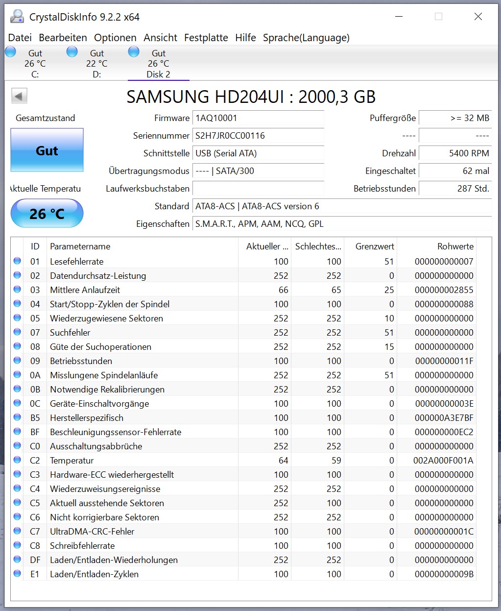
Screenshot der Software CrystalDiskInfo mit Festplatten-S.M.A.R.T.-Werten
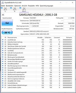
CrystalDiskInfo 9.2.2 x64 Datei Bearbeiten Optionen Ansicht Festplatte Hilfe Sprache(Language) Gut 26 °C C: Gut 22 °C D: Gut 26 °C Disk 2 SAMSUNG HD204UI : 2000,3 GB Firmware 1AQ10001 Puffergröße >= 32 MB Seriennummer S2H7JR0CC00116 Schnittstelle USB (Serial ATA) Drehzahl 5400 RPM Übertragungsmodus | SATA/300 Eingeschaltet 62 mal Laufwerksbuchstaben Aktuelle Temperatur 26 °C Betriebsstunden 287 Std. Standard ATA8-ACS | ATA8-ACS version 6 Eigenschaften S.M.A.R.T., APM, AAM, NCQ, GPL ID Parametername Aktuell ... Schlechtes... Grenzwerte Rohwerte 01 Lesefehler 100 100 51 000000000007
in „Daten von unwilligem langsamen FTP oder Netzlaufwerk sichern“ · PC Hard- und Software · · Screenshots
-
Datei
main.c
#include <stdint.h> void wait_cycles(int N) { volatile static int c = 0; for(int i = 0; i < N; i++) { c++; } } int main() { /* enable GPIO0 (bit 14) and IOCON (bit 13) clock in the SYSAHBCLKCTRL0 register */ *(volatile uint32_t*)0x400740C4 |= (1U << 13) | (1U << 14);
in „LPC1549 von Grund auf verstehen“ · Mikrocontroller und Digitale Elektronik ·