-
 Bild
Bild
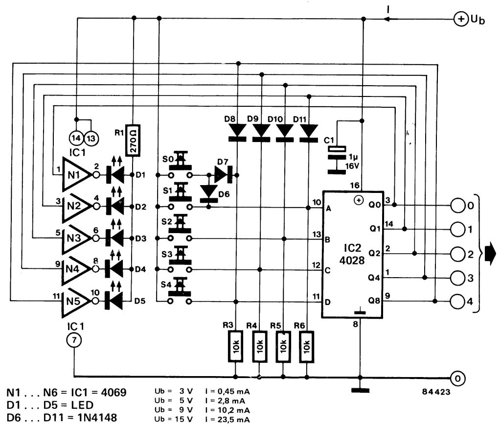
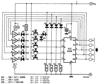
Schaltplan mit IC1 4069 und IC2 4028
LED, Ub = 3V, I = 0,45mA, Ub = 5V, I = 2,8mA, Ub = 9V, I = 10,2mA, D6...D11 = 1N4148, Ub = 15V, I = 23,5mA
-
Thread
SOT23-6 Bauteil mit SMD-Code 62642
Bei Mouser kann man Schaltregler mit SOT-23-6 suchen: https://www.mouser.de/c/semiconductors/power-management-ics/voltage-regulators-voltage-controllers/switching-controllers/?package%20%2F%20case=SOT-23-6 einfach mal die Datenblätter durchsuchen
Michael K. schrieb im Beitrag #7960472: > Im Primärkreis eines Schaltnetzteil ist ein Bauteil mit SOT23-6 Gehäuse > mit 6 Anschlüssen und SMD-Code 62642. https://www.rom.by/files/OB2262.pdf
-
 Bild
Bild
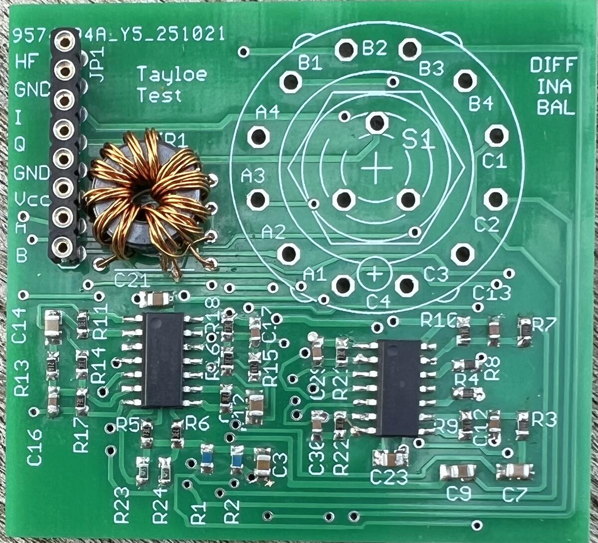
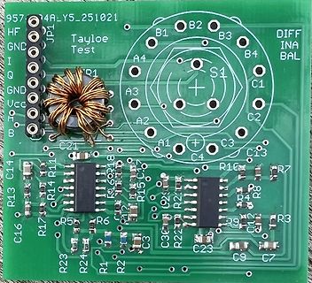
Leiterplatte mit Induktivität und SMD-Bauteilen
INA B3 BAL Q B4 A4 S1 C1 A3 C2 A2 C21 C3 C4 C13 C14 R11 R10 R15 R7 R13 R14 R17 R8 R5 R4 R9 R3 R6 R23 R24 R1 R2 C3 C23 C9 C7
-
 Bild
Bild
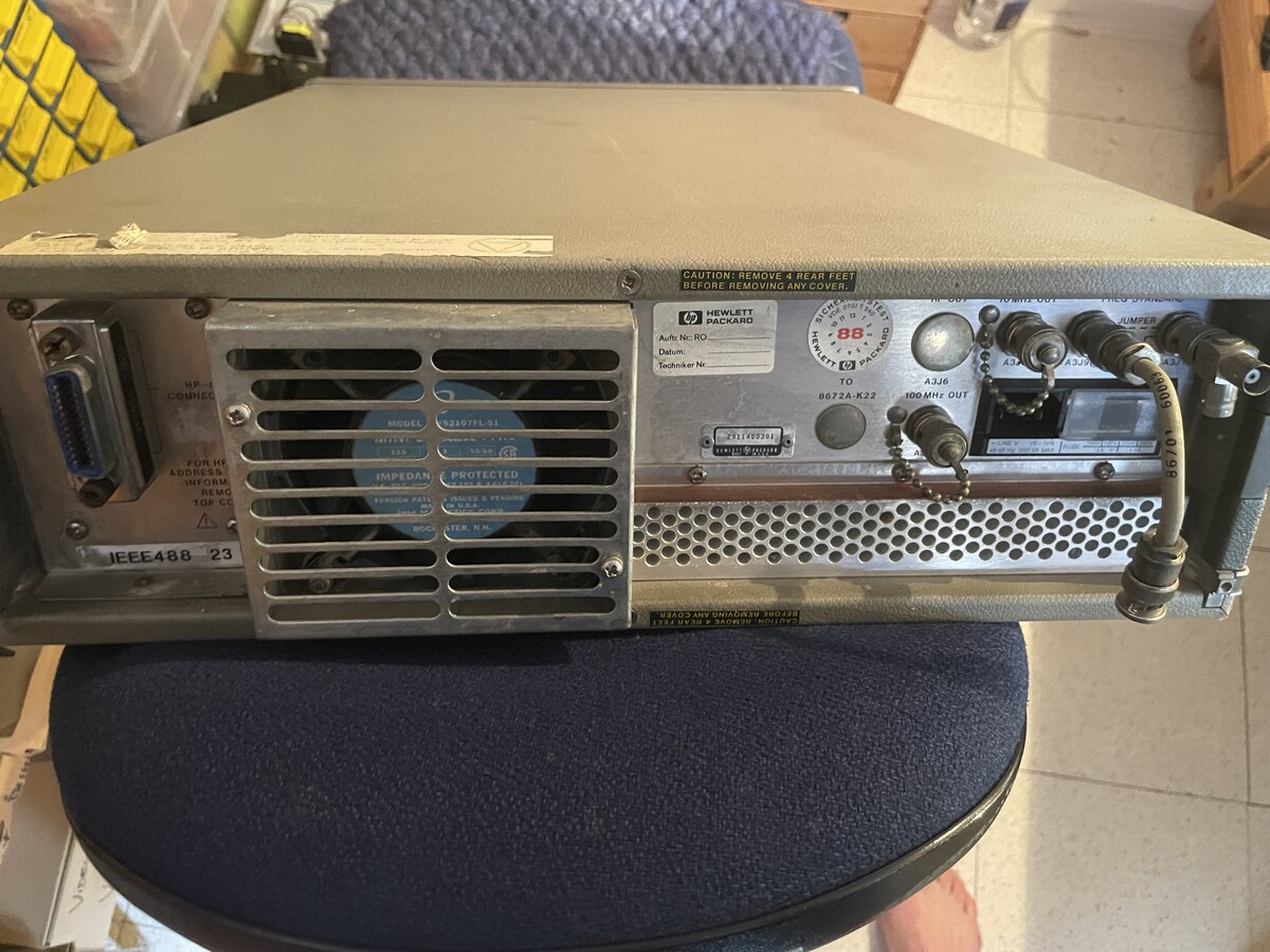
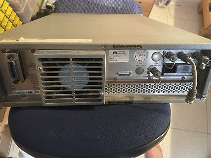
Rückseite eines Hewlett Packard Signalgenerators
REMOVE 4 REAR FEET BEFORE REMOVING ANY COVER. HEWLETT PACKARD MODEL 8672A-K22 100 MHz OUT IEEE488 23
-
Thread
E-Auto: Kontaktloses Laden während der Fahrt Gesperrt
Teststrecke auf der A6 bei Nürnberg inkl Interview und Probefahrt: https://youtu.be/7irK0Hpvmy0?si=u6d7PITS23W2P3Xw
-
 Bild
Bild
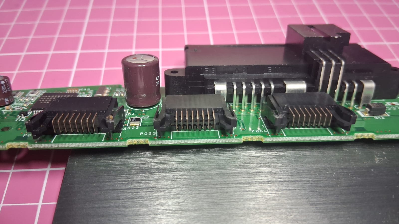
Nahaufnahme einer Leiterplatte mit Steckverbindern und Elektrolytkondensator
D4, BR22, P053, P054

-
 Bild
Bild
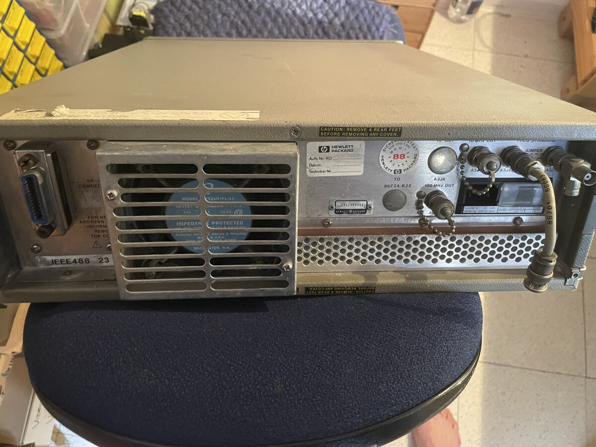
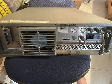
Rückseite eines Hewlett Packard Signalgenerators
REMOVE 4 REAR FEET BEFORE REMOVING ANY COVER. HEWLETT PACKARD MODEL 8672A-K22 100 MHz OUT IEEE488 23
-
 Bild
Bild
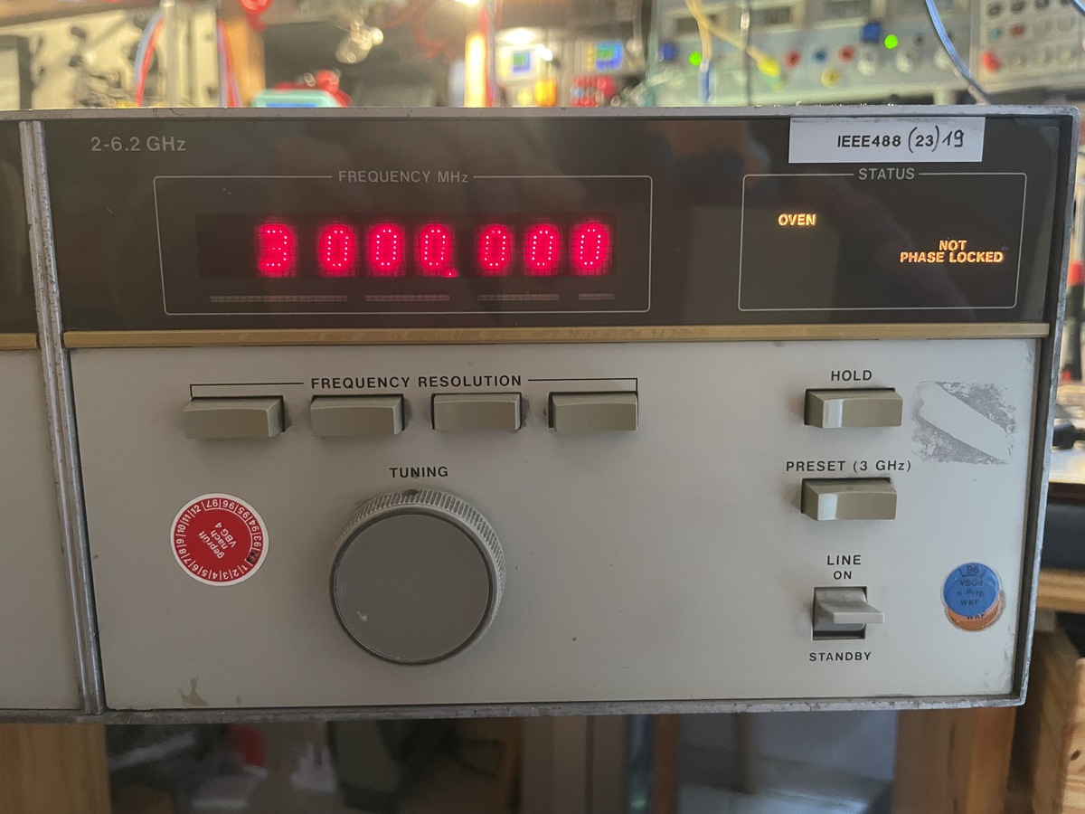
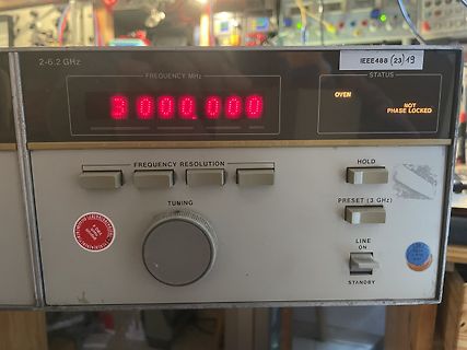
Frequenzgenerator mit LED-Display
2-6.2 GHz FREQUENCY MHz 3000.000 IEEE488 (23) 19 STATUS OVEN NOT PHASE LOCKED FREQUENCY RESOLUTION HOLD TUNING PRESET (3 GHz) LINE ON STANDBY
-
Thread
Android - Gesprächspartner kann mich manchmal bei einem Telfonat nicht hören
Harald K. (kirnbichler) 02.11.2025 23:01 Harald K. (kirnbichler) 02.11.2025 14:58 Wie so oft nur heiße Luft und Bla bla bla. Was kannst du eigentlich so außer Ammenmärchen und Großmutters Weissheiten? Du kennst dich doch so gut mit und
-
Thread
AVaRice DebugWire Breakpoints
02 00 00 00 00 00 00 02 00 06 03 00 00 04 80 00 recv: 0xe1 recv: 0x63 CRC OK Got message seqno 23 (command_sequence == 23) response: 82 AA F6 40 20 00 40 00 02 08 00 00 00 00 00 00 00 02 00 00 00 00 00 00 02 00 06 03 00 00 04 80 00 jtagRead command[0x05, 1]: 05 20 03 00 00 00 5D 00 00 00 recv
-
 Bild
Bild
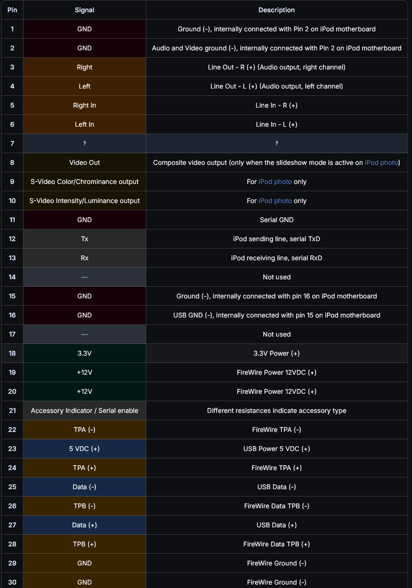
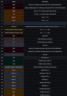
Pinbelegungstabelle eines iPod-Anschlusses
Indicator / Serial enable Different resistances indicate accessory type 22 TPA (-) FireWire TPA (-) 23 5 VDC (\+) USB Power 5 VDC (+) 24 TPA (+) FireWire TPA (+) 25 Data (-) USB Data (-) 26 TPB (-) FireWire Data TPB (-) 27 Data (+) USB Data (+) 28 TPB (+) FireWire Data TPB (+) 29 GND FireWire Ground (
-
 Bild
Bild
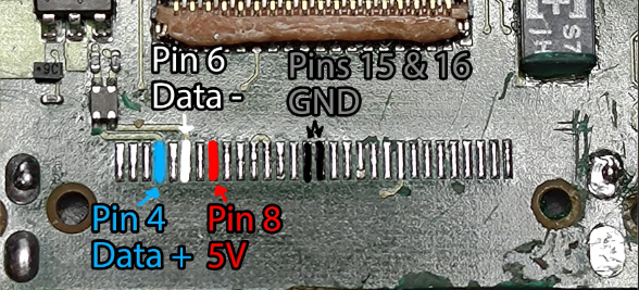
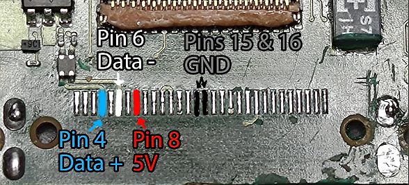
Leiterplatte mit Pin-Beschriftungen
Pin 6 Data - Pins 15 & 16 GND Pin 4 Data + Pin 8 5V
-
 Bild
Bild
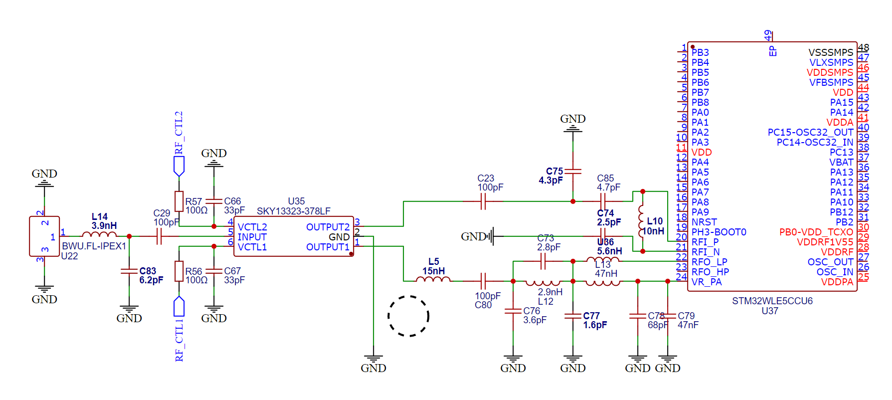
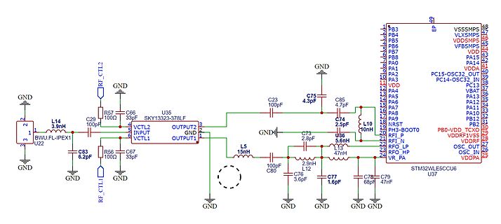
Schaltplan eines HF-Teils mit STM32WLE5CCU6
RF_CTL1 C83 6.2pF GND R57 100ohm C66 33pF SKY13323-378LF VCTL2 INPUT VCTL1 OUTPUT1 U35 C29 100pF C23 100pF R56 100ohm C67 33pF GND L5 15nH C80 100pF C73 2.8pF C76 3.6pF C74 2.5pF C77 1.6pF C75 4.3pF C85 4.7pF L10 10nH C79 47nF C78 47nF U36 RF_I_N RF_O_LP RF_HO RF_PA VR_PA VDDPA PB0-VDD_TCXO VDD RF_I_N
-
 Bild
Bild
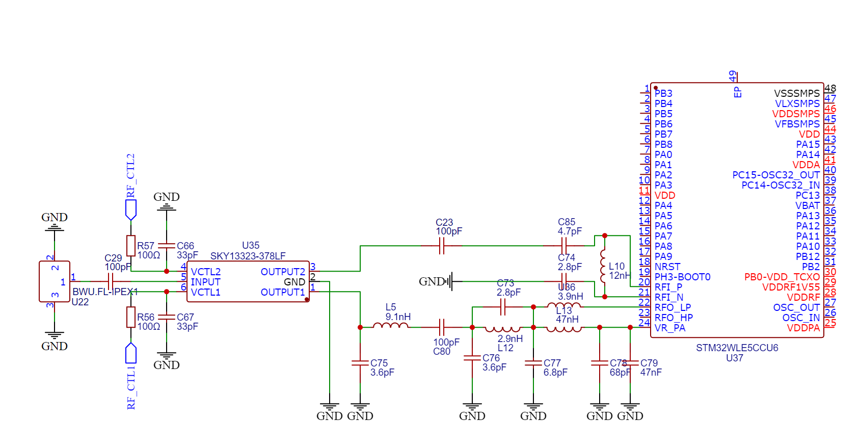
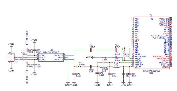
Schaltplan eines HF-Teils mit STM32WLE5CCU6
378LF U35 VCTL1 INPUT VCTL2 INPUT OUTPUT2 GND OUTPUT1 U22 BWU_FL_IPEX4 R56 100Ω C67 33pF RF_CTL1 GND C23 100pF C85 4.7pF C74 L10 12nH GND L5 9.1nH C80 100pF C76 3.6pF L13 47nH C77 6.8pF C75 3.6pF C79 47pF U36 3.9nH GND GND GND U37 STM32WLE5CCU6 PB3 VSSMPS PB4 VLXSMPS PB5 VDDSMPS PB6 VFBSMPS PB7 PA15 PA0
-
Thread
Diskussion über 50er Roller 4 Takter Einspritzanlagen.
Interessanterweise habe ich noch etwas gewühlt und fand heraus, dass bei der Unfallursache unter Drogen (23%) der Alkohol (-5% =18%) nicht einmal die relative Mehrheit erreicht. Es sind die Drogen wie Cannabis (Hauptquelle), Hanf, Marihuana, Opiate usw. und darunter noch eine Gruppe, deren Medikamente darunter
Beitrag #7963758: >> Flory hieß die kleine Kreidler Mofa. http://www.kreidler-museum.de/77floy23.htm > Es gab noch mehr Modelle, in allen drei/vier Kategorien. Es gibt bei kreidler-museum viele Beschreibungen, aber eine total dämliche Webseite - da finde ich nur etwas über Google.
-
 Bild
Bild
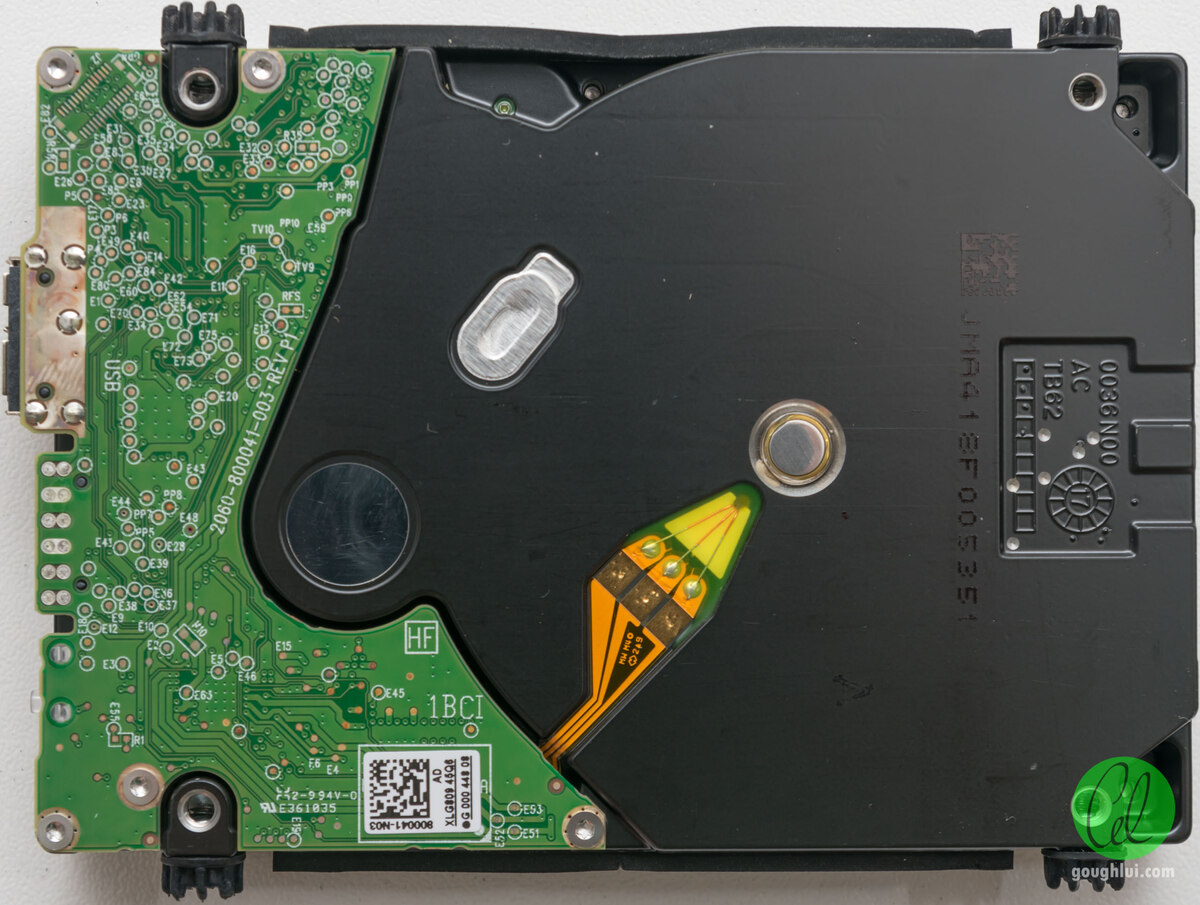
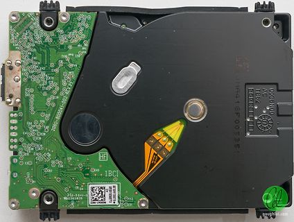
Hartplatte mit Leiterplatte
8000041-003-RV-P USB E1 E2 E3 E4 E5 E6 E7 E8 E9 E10 E11 E12 E13 E14 E15 E16 E17 E18 E19 E20 E21 E22 E23 E24 E25 E26 E27 E28 E29 E30 E31 E32 E33 E34 E35 E36 E37 E38 E39 E40 E41 E42 E43 E44 E45 E46 E47 E48 E49 E50 E51 E52 E53 E54 E55 E56 E57 E58 E59 E60 E61 E62 E63 E64 E65 E66 E67 E68 E69 E70 E71 E72 E73
-
 Bild
Bild
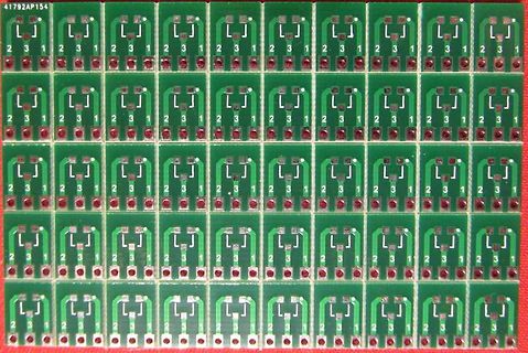
Nahaufnahme einer Leiterplatte mit repetitiven Lötpads
41792AP154 L 1 2 3
-
 Bild
Bild
Schaltplan einer elektronischen Schaltung
R12 360, R13 360, R14 360, R15 360, R16 360, R17 360, R18 360, R19 360, R20 360, R21 360, R22 360, R23 360, R24 360, R25 360, R26 360, R27 360, R28 360, R29 360, R30 360, R31 360, R32 360, R33 360, R34 360, R35 360, R36 360, R37 360, R38 360, R39 360, R40 360, R41 360, R42 360, R43 360, R44 360, R45 360
-
Thread
rtc winterzeit automatisch umstellen
und z.B. auch GPS-Zeit) mit "nur" zwischengeschobenem, aber immerhin keinem doppelten Uhrzeitwert "23:59:60". Gibt es bei vielen Unix-Systemen mit vorzeichenbehafteter 32-Bit Zeit nicht das Problem, dass Zeiten vor dem 13.Dez 1901 und nach dem 19. Jan 2038 zum Variablenüberlauf führen? Da kann
-
Thread
24-Kanal PWM Led-Controller mit key-scan
keine 25mA liefern (zumindest ist es grenzwertig) aber 10mA sicher. Oder man nimmt einen LL-FET in SOT-23, der kann dann auch mehrere LED bedienen. Die PWM liefert der µC.
25mA liefern (zumindest ist es grenzwertig) aber 10mA sicher. > Oder man nimmt einen LL-FET in SOT-23, der kann dann auch mehrere LED > bedienen. Die PWM liefert der µC. 25mA pro LED reichen. Es würde ausreichen, die LEDs gemeinsam schalten zu können, sie könnten in Reihe geschaltet werden. Aber
-
 Bild
Bild
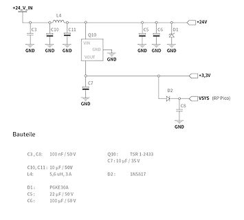
Schaltplan eines DC-DC-Wandlers
+24_V_IN L4 C3 C10 C11 Q10 VIN VOUT GND C5 C6 D1 +24V GND GND GND C7 +3,3V GND D2 VSYS (RP Pico) C8 GND Bauteile C3, C8: 100 nF / 50 V C10, C11: 10 µF / 50V L4: 5,6 µH, 3 A D1: P6KE30A C5: 22 µF / 50 V C6: 100 µF / 50 V Q10: TSR 1-2433 C7: 10 µF / 35 V D2: 1N5817
-
 Bild
Bild
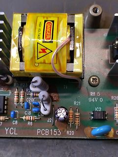
Nahaufnahme einer Leiterplatte mit Transformator
DANGER HIGH VOLTAGE R5 R23 R22 C20 C18 C10 T1 5 94V0 R21 IC2 R26 C8 R6 J2 YCL PCB153 R20
-
Thread
Visual Studio Code für Raspberry Pi Pico, neue Mikrocontroller uvam
Zustand. Der Erfinder der SCHOTTKY-Diode war Walter Schottky, ein deutsch-schweizer Physiker, * 23.7.1886 Zürich, † 4.3.1976 Forchheim, ⚰ Pretzfeld (Oberfranken), der bei Max Planck promoviert hat.
-
Thread
Austauschtyp für IRL 3803
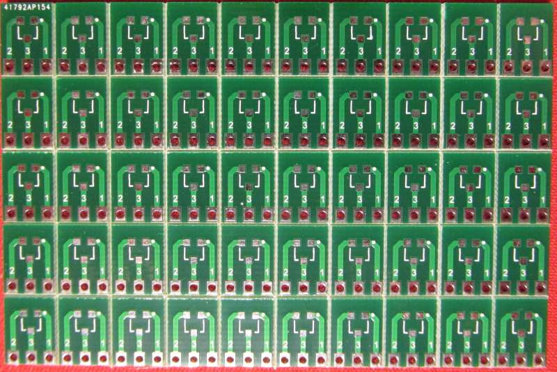
Nimm was in DPAK, SOT223 oder SOT23 und route dir Adapterplatinen und bestelle davon beim Chinesen "ne Schubkarre voll". Damit hast du es in der Hand, das sie pinkompartibel sind. Da lötest du was Aktuelles drauf und hast dann für Lochraster
inklusive – bis > 0201 hinab, wenn es sein muss). In einem anderen Thread hat der User Stefan K. SOT23 auf Stiftleisten gelötet, gefällt mir sehr gut und habe ich dann auch mal ausprobiert. https://www.mikrocontroller.net/topic/565297#7623684 https://www.mikrocontroller.net/attachment/627810/SOT23
-
Thread
Object Oriented Forth
Andreas H. (ahz) 09.11.2025 02:23 >Diesen "speziellen" Prozessor kannst Du auch selber probieren: >https://github.com/jamesbowman/swapforth/tree/master/j1a Danke für den Link. In den Anfängen der J1 gab es ein Paper und ein
-
 Bild
Bild
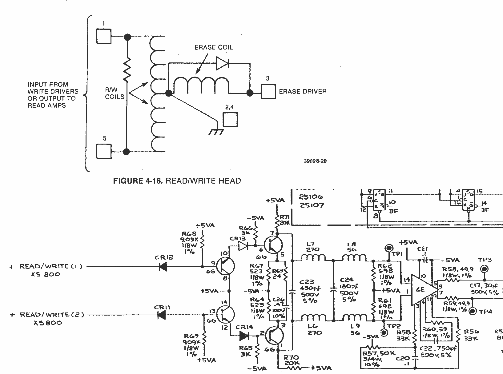
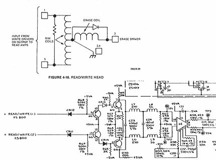
Schaltplan eines Schreib-Lese-Kopfes
WRITE (1) XS 800 +READ/WRITE (2) XS 800 +5VA -5VA R68 909K 1/8W 1% CR13 3K 6G 10 6G R67 523 1/8W 1% C23 430pF 500V 5% C24 180pF 500V 5% L7 270 L8 56 TPI 25106 25107 GE -5VA R58 49.9 1/8W 1% C21 TP3 C17 30pF 500V 5% TP4 R59 49.9 1/8W 1% R56 33 1/8W 1% C20 22.75pF 500V 5% R57 50K 3/4W 10% L9 56 LG 270 R65
-
 Bild
Bild
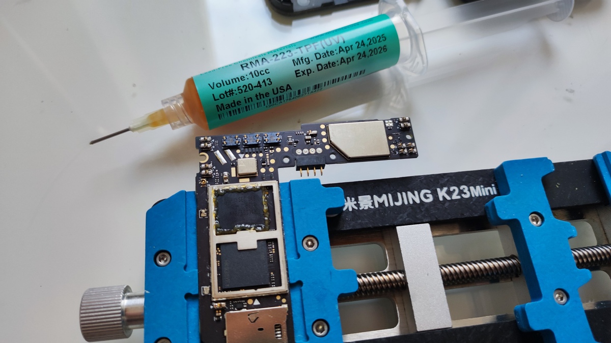
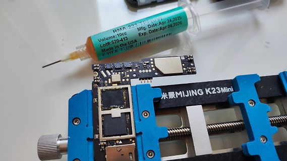
Leiterplatte und Spritze mit Klebstoff
TPF(UV) Volume:10cc Lot#:520-413 Made in the USA Mfg. Date:Apr 24,2025 Exp. Date:Apr 24,2026 MIJING K23Mini
-
 Bild
Bild
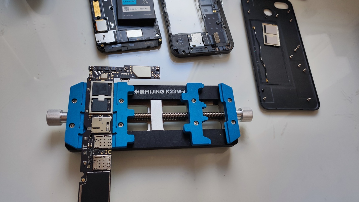
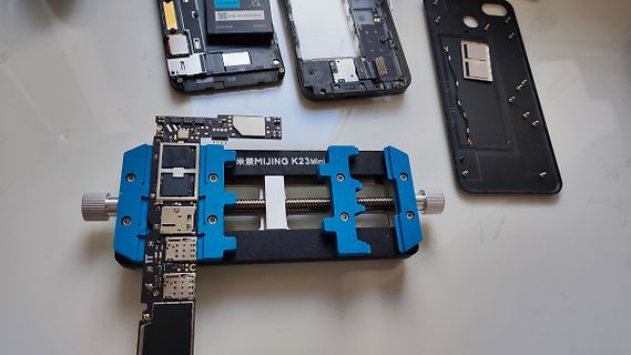
Zerlegte Smartphone-Komponenten und Werkzeug
Li-Ion 3.8V, AK10035A.24, MIJING K23Mini
-
 Bild
Bild
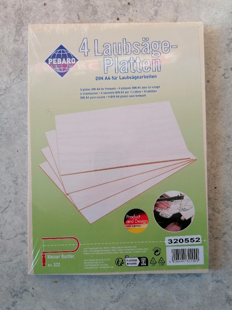
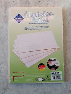
Verpackung von 4 Laubsäge-Platten
Design made in germany 320552 Kleiner Bastler. Art. 322 Pixor Bogen GmbH & Co. KG Blomberg Straße 21-23 32528 Blomberg/Westfalen www.pixor-bogen.de [CE] [WEEE symbol] PLASTIQUE + PAPIER MADE IN GERMANY 4 030694 320552
-
Thread
Kurioser DC-DC Step Down Converter
taugt nur für 2A/18V statt 3A/28V des MP1584. Auch wenn er die 2A nicht bringt, zumindest soll er 23V aushalten: "The EA8252 is a 2A buck regulator, designed to operate from 4.6V to 23V input voltage range." http://www.everanalog.com/Product/ProductEA8252DetailInfo.aspx Hat jemand ein EA8252 Datenblatt
das Datenblatt. Die Firma ist ja nicht besonders vertrauenserweckend, wenn die Produktseite 4,6 bis 23V angibt, das nicht offen zugängliche Datenblatt aber nur "4.5V to 18V Input Voltage Range" zulässt! Das erinnert mich an das 24V step down modul wo der 24V MP2315 durch einen 16V RY7135 ersetzt wurde
-
 Bild
Bild
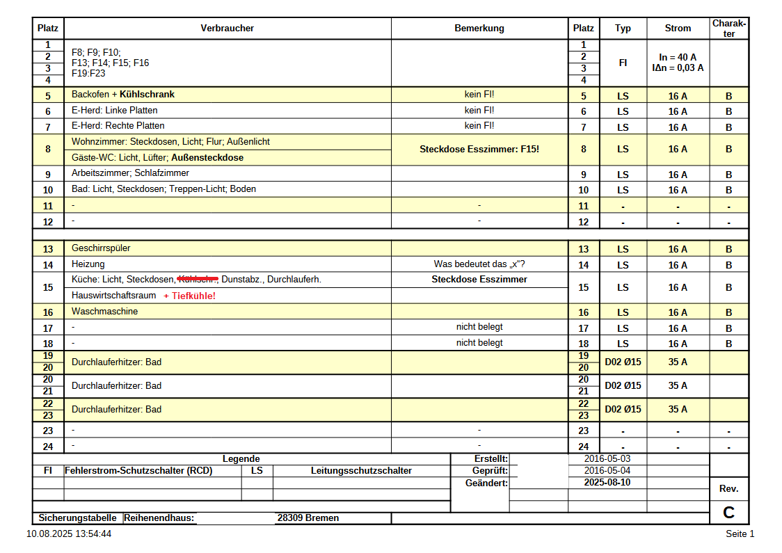
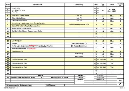
Sicherungstabelle eines Reihenendhauses
Bemerkung Platz Typ Strom Charakter 1 F8; F9; F10; 2 FI In = 40 A 3 F13; F14; F15; F16 3 FI 4 F19; F23 4 5 Backofen + Kühlschrank kein FI 5 LS 16 A B 6 E-Herd: Linke Platten kein FI 6 LS 16 A B 7 E-Herd: Rechte Platten kein FI 7 LS 16 A B 8 Wohnzimmer, Steckdosen, Licht; Flur; Außenlicht Steckdose Esszimmer
-
 Bild
Bild
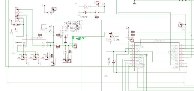
Schaltplan mit ATtiny45 und ATmega8 Mikrocontroller
PH07, PH08, PH09, PH10, PH11, PH12, PH13, PH14, PH15, PH16, PH17, PH18, PH19, PH20, PH21, PH22, PH23, PH24, PH25, PH26, PH27, PH28, PH29, PH30, PH31, PH32, PH33, PH34, PH35, PH36, PH37, PH38, PH39, PH40, PH41, PH42, PH43, PH44, PH45, PH46, PH47, PH48, PH49, PH50, PH51, PH52, PH53, PH54, PH55, PH56,
-
 Bild
Bild
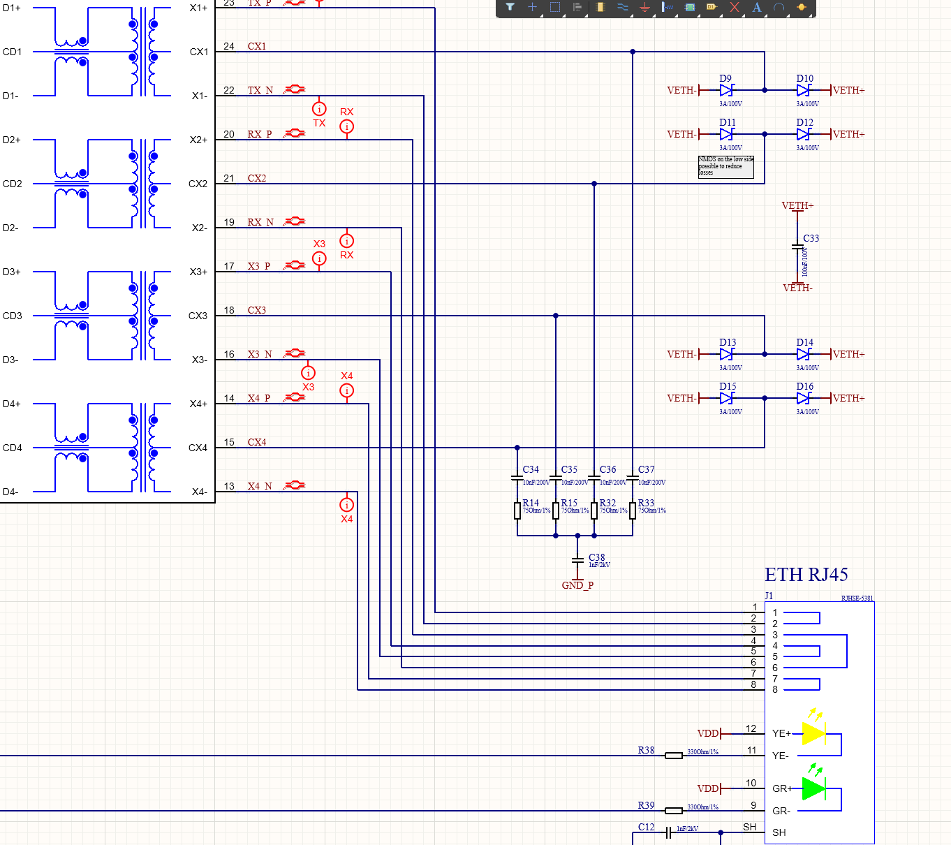
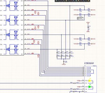
Schaltplan einer Ethernet-Schnittstelle mit Transformator-Anbindung
, X3+, X4+, D2-, CD2, D2+, CX2, X2-, X3-, D3-, CD3, D3+, CX3, X3, X4, D4-, CD4, D4+, CX4, X4-, X4, 23 TX P, 24 CX1, 22 TX N, RX P, TX, D9, 10V, D10, 10V, VETH+, D11, 10V, D12, 10V, VETH+, VETH+, C33, 100nF, VETH-, D13, 10V, D14, 10V, VETH+, D15, 10V, D16, 10V, VETH+, C34, 100nF, C35, 100nF, C36, 100nF
-
Thread
Win11 CPU läuft im Akkubetrieb nur mit geringsten Takt langsam
einige Sekunden blockierte und außerdem zu viel Kernel-Rechenzeit verbrauchte. Je nach Version 23H2, 24H2 oder 25H2 wurde von Microsoft versucht diese Probleme zu beheben, was aber wieder andere Seiteneffekte erzeugt. - So langsam wissen die anscheinend selbst nicht mehr, was sie machen. Sven
Sven L. schrieb im Beitrag #7958325: > Je nach Version 23H2, 24H2 oder 25H2 wurde von Microsoft versucht diese > Probleme zu beheben, was aber wieder andere Seiteneffekte erzeugt. - So > langsam wissen die anscheinend selbst nicht mehr, was sie machen.
-
Thread
CH23V003 und Arduino: Verwendung Timer2 Interrupt
Auch wenn es eine nur eventuell kleine Zielgruppe gibt (und ich jetzt ein klein wenig "gekämpft" habe): Die Benutzung des Timer2 Interrupts mit Arduino und CH32V003 anhand eines "typischen Blinkprogramms". Die wichtigste Angabe hier ist extern "C" bei der Deklaration des Interrupthandlers, weil Arduino C++ ist und ohne diese Deklaration der Handler in der Vektortabelle nicht gefunden werden kann (name mangling). Wer es gebrauchen kann: bitte bedienen !
-
 Bild
Bild
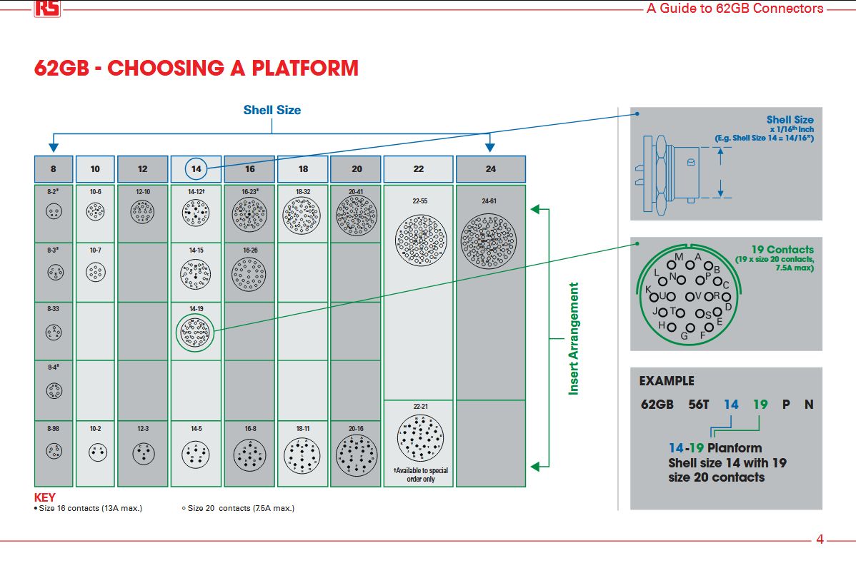
Tabelle zur Auswahl von 62GB Steckverbinder-Plattformen
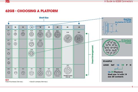
62GB - CHOOSING A PLATFORM Shell Size 8 10 12 14 16 18 20 22 24 8-2* 10-6 12-10 14-12* 16-23* 18-32 20-41 22-55 24-61 8-3* 10-7 14-15 16-26 8-33 14-19 8-4* 22-21 8-98 10-2 12-3 14-5 16-8 18-11 20-16 8-9* KEY * Size 16 contacts (13A max.) o Size 20 contacts (7.5A max.) 1 Available to special
-
Thread
Das Statron 3217/16 Projekt
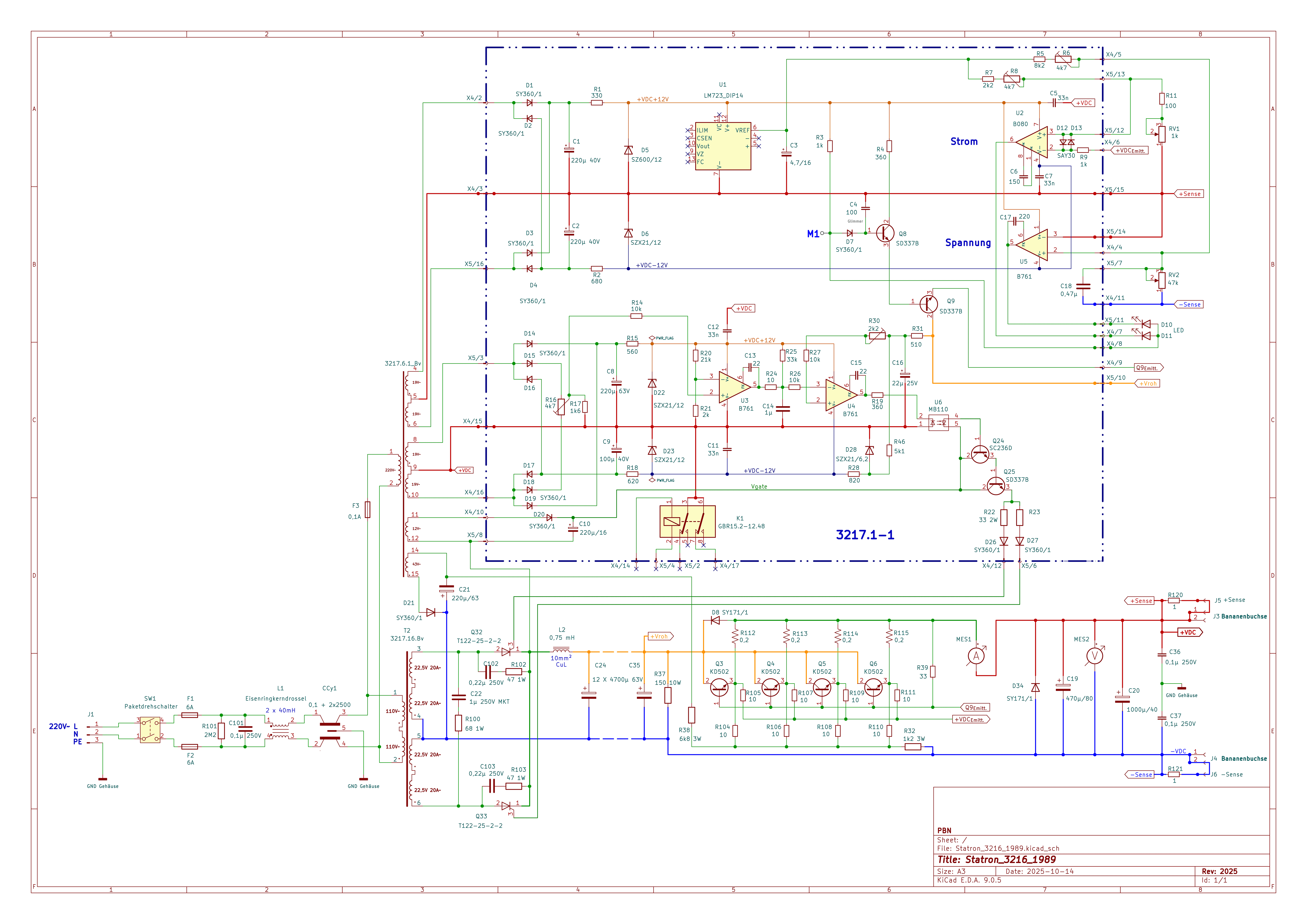
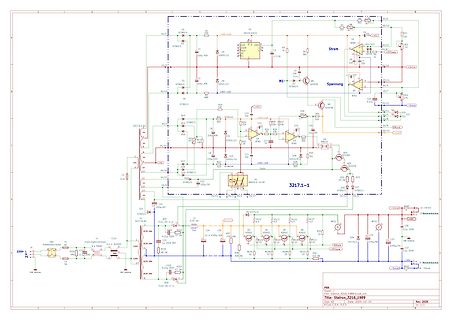
generierten Zündimpulse ist ein Optokoppler eingesetzt. Interessant sind die beiden Widerstände R22 und R23 welche den Zündstrom bestimmen. In der älteren Baureihe waren es 180 Ohm, jetzt 33 Ohm. Statron hat den Zündstrom deutlich erhöht. Beim Hauptregler sind die beiden OpAmps A109 ersetzt durch B080
-
Thread
Eigener DSLAM im Keller möglich?
Datendose ans Telefonkabel https://www.reichelt.de/de/de/shop/kategorie/rj45-datendosen-5997?filter=112%23~%23%2A%23~%231x%20RJ45%20%23~%231x%20RJ45%23~%230 und dann die Fritzbox als Router mit externem Modem betreiben. Die Verbindung ist dann normales Ethernet, nur eben über ein nicht ganz optimales Kabel
ans Telefonkabel > > https://www.reichelt.de/de/de/shop/kategorie/rj45-datendosen-5997?filter=112%23~%23%2A%23~%231x%20RJ45%20%23~%231x%20RJ45%23~%230 Gibt bestenfalls 100MBit/s.
-
 Bild
Bild
Nahaufnahme einer Leiterplatte mit Messleitungen
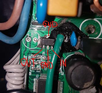
C2, C3, C4, C5, C6, C7, C8, C9, C10, C11, C12, C13, C14, C15, C16, C17, C18, C19, C20, C21, C22, C23, C24, C25, C26, C27, C28, C29, C30, C31, C32, C33, C34, C35, C36, C37, C38, C39, C40, C41, C42, C43, C44, C45, C46, C47, C48, C49, C50, C51, C52, C53, C54, C55, C56, C57, C58, C59, C60, C61, C62, C63
-
 Bild
Bild
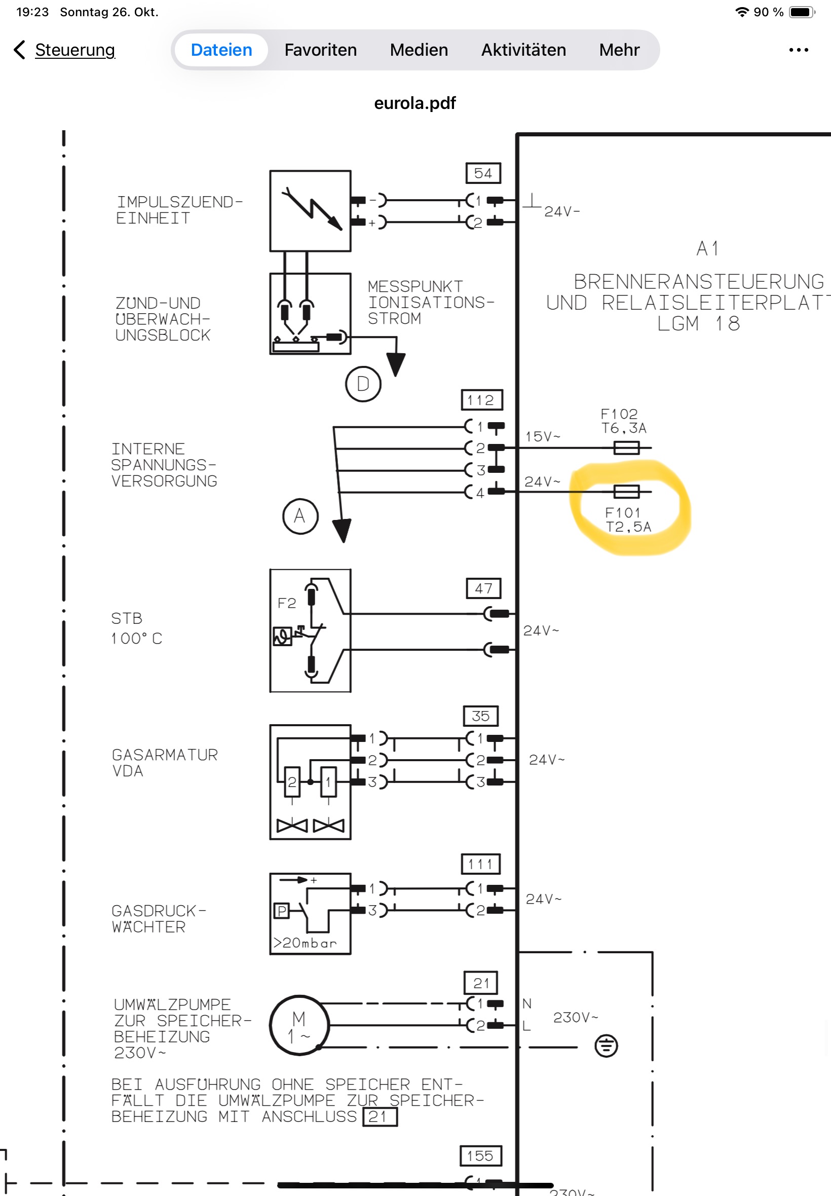
Schaltplan einer Brennersteuerung
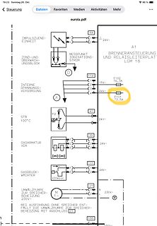
eurola.pdf 19:23 Sonntag 26. Okt. 90% Dateien Favoriten Medien Aktivitäten Mehr Steuerungen IMPULSZUEND-EINHEIT 54 24V- A1 BRENNERANSTEUERUNG UND RELAISLEITERPLAT LGM 18 MESSPUNKT IONISATIONS-STROM D 112 T6,3A 15V- F102
-
 Bild
Bild
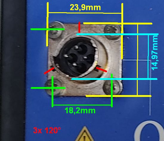
Messung der Abmessungen eines Steckverbinders
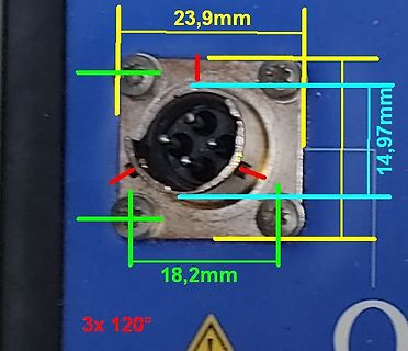
23,9mm 14,97mm 18,2mm 3x 120°
-
Thread
[V] ADP2442ACPZ ADP1710AUJZ-2.5 USB2514B SGTL5000XNAA3R2 MICMTFC4GMVEA-4M
Reel 1€/Stück, 200€ fürs Reel **Analog ADP1710AUJZ-2.5-R7** 2.5V LDO 150mA, 2.5-5.5Vin TSOT-23-5 Datecode: 1220 Datasheet https://eu.mouser.com/datasheet/3/1014/1/ADP1710_1711.pdf Angefangenes 3000er Reel 0,5€/stück, 100€ fürs Reel **Microchip USB2514B-AEZG** 4 Port USB 2.0 Hub
526211/MICRON/MTFC4GMVEA-4MIT.html 6 Stück im Tray 2€/Stück Versand aus AT, Abholung in Wien 23. Bezirk möglich.
-
 Bild
Bild
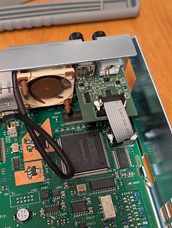
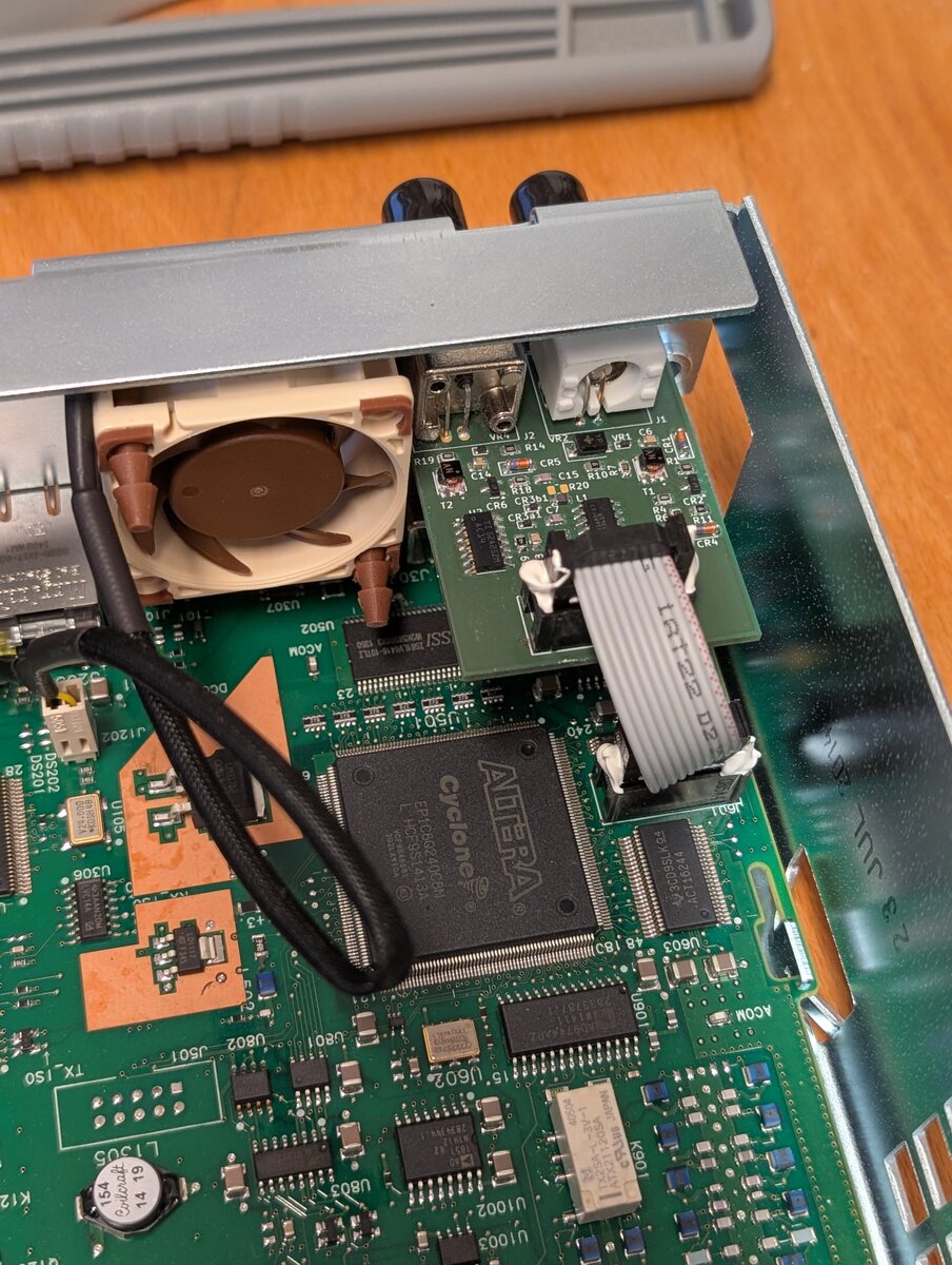
Detailaufnahme einer Leiterplatte mit Altera Cyclone FPGA
U062, U063, U061, U021, U022, U051, U052, U060, L305, R12, C15, C16, C17, C18, C19, C20, C21, C22, C23, C24, C25, C26, C27, C28, C29, C30, C31, C32, C33, C34, C35, C36, C37, C38, C39, C40, C41, C42, C43, C44, C45, C46, C47, C48, C49, C50, C51, C52, C53, C54, C55, C56, C57, C58, C59, C60, C61, C62, C63