-
 Bild
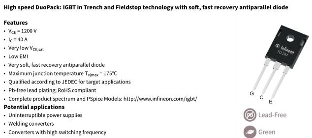
Datenblattseite eines Infineon IGBT DuoPack
High speed DuoPack: IGBT in Trench and Fieldstop technology with soft, fast recovery antiparallel diode Features VCE = 1200 V IC = 40 A Very low VCE,sat Low EMI Very soft, fast recovery antiparallel diode
-
Thread
XC3S400 Ersatz
> so beworben, Die Aussage, das der GateMate als Spartan-Ähnlicher-FPGA (und damit Ersatz für LowCost-FPGA) gedacht ist, stammte von einen CologneChip-Mitarbeiter auf der electronica letzte Woche. Im Anhang Scan vom Flyer von ChipCologne zum Thema Migration von Spartan.
im Beitrag #7779265: > Die Aussage, das der GateMate als Spartan-Nachbau (und damit Ersatz für > LowCost-FPGA) gedacht ist, stammte von einen CologneChip-Mitarbeiter auf > der electronica letzte Woche. Dann muessten ja bei Digikey die LQFP-Varianten davon irgendwann auftauchen. Es gab anfangs
-
Thread
S8050 Reihenschaltung?
So sieht es aus. Ich habe aber das Problem, dass der Transistor immer schaltet, egal ob ich LOW oder HIGH drauf gebe. wie löse ich das?
sieht es aus. > > Ich habe aber das Problem, dass der Transistor immer schaltet, egal ob > ich LOW oder HIGH drauf gebe. wie löse ich das? Das geht so nicht. Wenn du einen PNP mit der Spannung von +12V am Emitter abschalten willst, muss die Basisspannung (knapp) +12V sein. Das kann der Ausgang
-
Thread
Speicher aus alten E-Auto Akkus
nickel-cadmium. Satellites primarily use batteries with large lithium-ion cells. These batteries provide high-energy levels and long cycle life at a low weight and in small volumes.
> Satellites primarily use batteries with large lithium-ion cells. These > batteries provide high-energy levels and long cycle life at a low weight > and in small volumes. Warum schreibst Du unseren englichsprachigen Usern etwas anderes als uns?
-
Thread
ESP8266 - LED falsch gepolt betreiben
als Ausgang definieren pinMode(redLED, OUTPUT); // Alle LEDs aus (da verpolt, müssen wir HIGH setzen, um sie auszuschalten) digitalWrite(redLED, HIGH); // Rot aus // Webserver-Routen einrichten server.on("/test", []() { // Test: LED ein und aus digitalWrite(redLED, LOW)
Vcc, die Kathode jeder LED einzeln (über einen Vorwiderstand) an einen µC-Pin. Und wenn dort dann "low" ausgegeben wird, dann leuchtet die LED. Das Ganze nennt sich im Fachbegriff auch "low-aktiv", weil hier die LED leuchtet, wenn der Ausgang low ist. Und ob eine 0 oder eine 1 ausgegeben wird,
-
Thread
[S] Reflow-Ofen für Prototyping und Kleinserienproduktion / DE-HH
(ziemlicher Schrotthaufen) und nach Validierung können wir die zur Fertigung rausgeben (ist dann high volume low mix, also gut extern abbildbar). Viele Grüße Alex
-
Thread
Ritto 17230 Klingelsignal mit ESP32 abgreifen
Pull-Up Widerstand auf der ESP32 Seite führt dazu, dass auf dem GPIO 3,3 Volt anliegen und somit ein HIGH Wenn es klingelt liegen 5 Volt zu GND an: Der MOSFET macht auf, und zwischen Drain und Source liegt eine Verbindung vor. Dadurch liegt über GND 0 Volt an dem GPIO und somit ein LOW an. - Der
-
 Bild
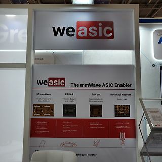
Werbeplakat für weasic mmWave ASIC Enabler
Vehicles, Security and Health SatCom Satellite to Earth Communications Backhaul Network Radio Links High performance Front end modules Ultra low phase noise Synthesizers Low power foundation analog IP 77GHz Sensors Fast and ultra linear FMCW Synthesizers Receiver and Transmitter Arrays Low phase noise Synthesizers up to 16 GHz Phased Array Transceivers sub-6GHz up to D-band Fully integrated high performance Transceivers RFwave™ Partner
-
 Bild
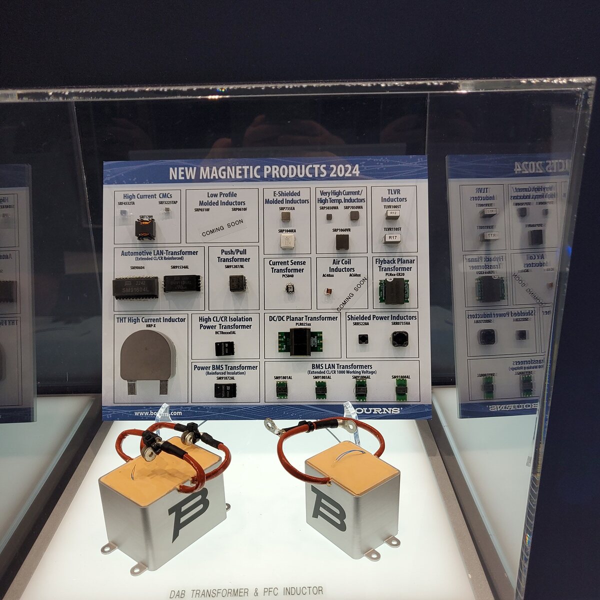
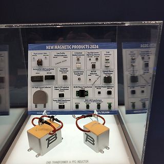
Produktübersicht magnetischer Komponenten und Induktoren
NEW MAGNETIC PRODUCTS 2024 High Current CMCs Low Profile Molded Inductors E-Shielded Molded Inductors Very High-Current/High Temp. Inductors TLVR Inductors Automotive LAN-Transformer Push/Pull Transformer Current Sense Transformer Air Coil Inductors Flyback Planar Transformer THt High Current Inductor High CL/CR Isolation Power Transformer DC/DC Planar Transformer Shielded Power Inductors Power BMS Transformer BMS LAN Transformers DAB TRANSFORMER & PFC INDUCTOR www.b...com
-
 Bild
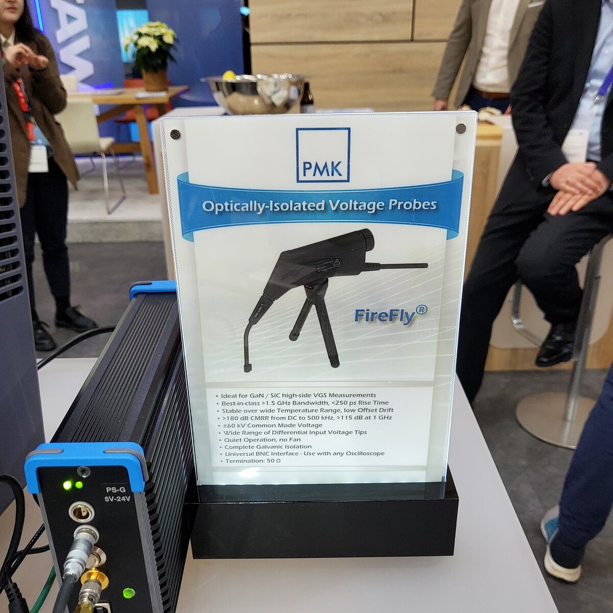
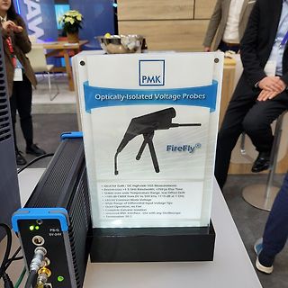
Werbeschild für optisch isolierte Spannungstastköpfe
PMK Optically-Isolated Voltage Probes FireFly® • Ideal for GaN / SiC high-side VGS Measurements • Best-in-class >1.5 GHz Bandwidth, <250 ps Rise Time • Stable wide Temperature Range, low Offset Drift • >180 dB CMRR from DC to 500 kHz, >115 dB at 1 GHz • <60 V Common Mode
-
 Bild
3D-gedruckte Box mit Wurth Elektronik MXGI Material
MXGI LOW LOSSES WE Wurth Elektronik MORE THAN YOU EXPECT With the WE-MXGI Wurth Elektronik offers its newest made power inductor series. It combines an innovative iron alloy material that provides an permeability
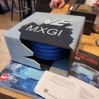
-
 Bild
Flyer für IQD OCXO Oszillatoren
IQD NEW at electronica 2024 Small Package OCXO High Stability 10 MHz, 19.2 MHz, 20 MHz Low Phase Noise Low Power -40 to 95 °C Operating Temp HCMOS Output IQOV-116 Series 7.5 x 5.5mm Applications: Wireless Communications Small Cell Communication Infrastructure
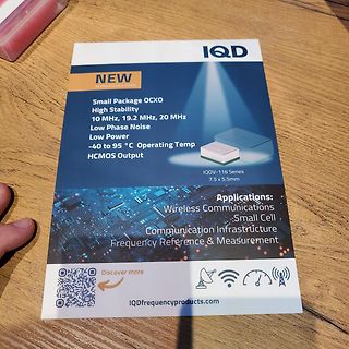
-
 Bild
Werbebild für Panasonic LPS4010 Serie Leistungsinduktivitäten
LPS4010 Series Low-profile power inductors offer high performance in a compact package. Only 1 mm in Height! C 861D 3.90 mm AEC Q200 +125°C Panasonic
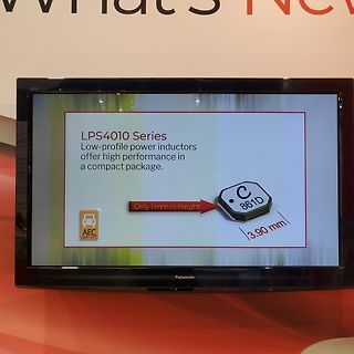
-
 Bild
Nichicon GYD Serie Elektrolytkondensatoren und Informationsschild
GYD Series Technology: Hybrid-SMD High Reliability, Low ESR, High Ripple Current, Long Life Temperature range: -55 to +150°C Size [mm]: 8Dx10L to 10Dx10L Voltage: 25 to 35V Capacitance: 100 to 270µF NICHICON (AUSTRIA) GMBH 14 270E GYD 14
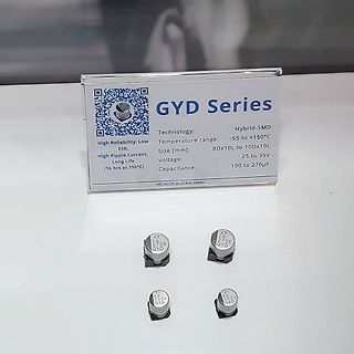
-
 Bild
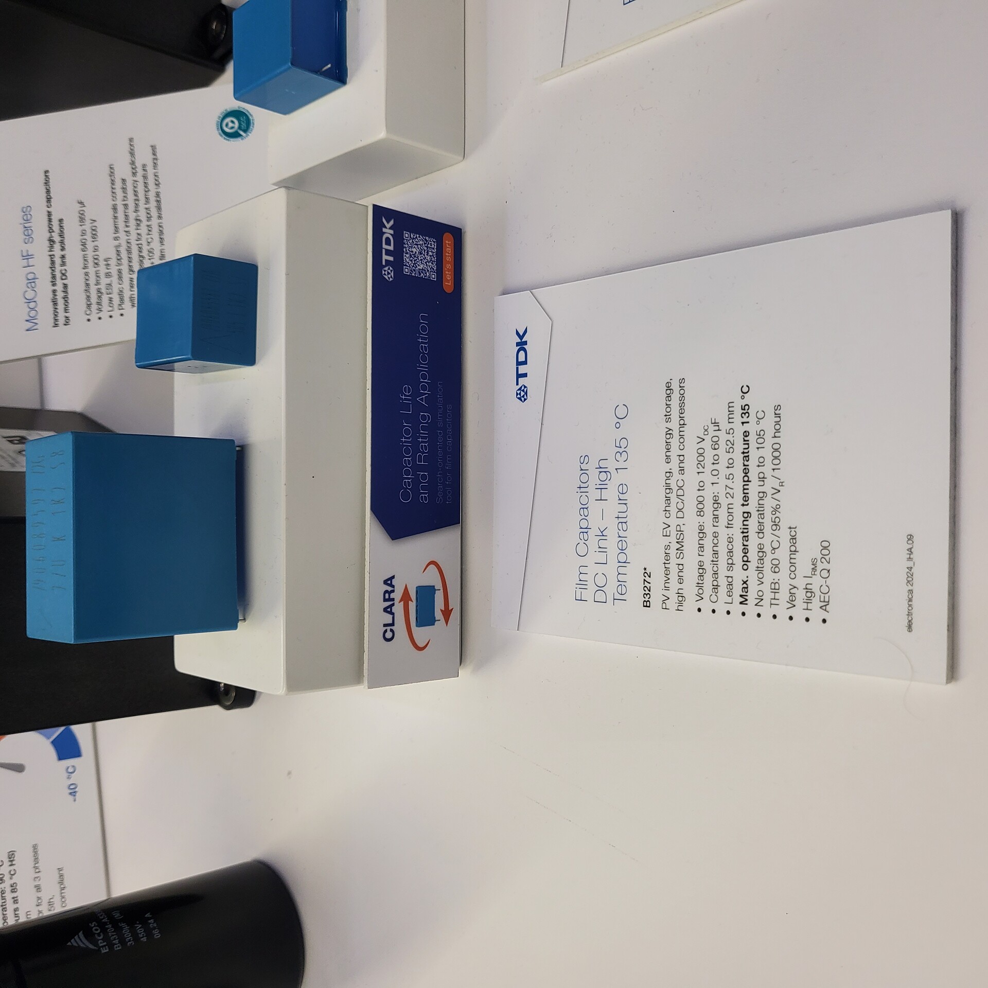
TDK ModCap HF Filmkondensatoren und Informationsmaterial
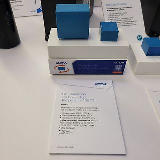
ModCap HF series Capacitance from 940 to 1860 µF Voltage from 900 to 1500 V Low ESR (B/H) High current generation of terminal holder for high-frequency applications up to 105 °C hot spot temperature Film version available upon request CLARA Capacitor Life and Rating Application TDK Film Capacitors DC Link – High Temperature 135 °C B3272* PV inverters, EV charging, energy storage, high end SMSP, DC/DC and compressors Voltage range: 800 to 1200 V_DC Capacitance range: 1.0 to 60 µF Lead space: from 27.5 to 52.5
-
 Bild
Werbeplakate für Pickering Reed Relays
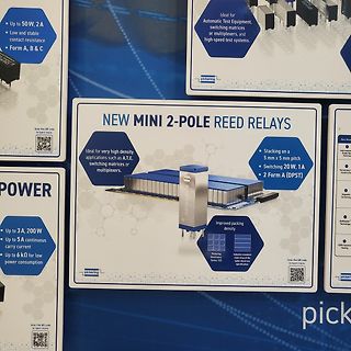
Up to 50 W, 2 A Low and stable contact resistance Form A, B & C Ideal for Automatic Test Equipment, switching matrices or multiplexers, and high-speed test systems. pickering NEW MINI 2-POLE REED RELAYS Scan the QR code
-
 Bild
Präsentation von Soft Termination Multilayer Ceramic Capacitors
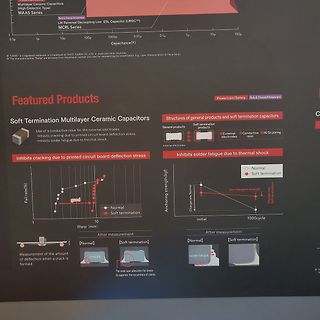
Multilayer Ceramic Capacitors (High Dielectric Type) MAAS Series LW Reversal Decoupling Low ESL Capacitor (LWDC™) PCRL Series Capacitance(F) Featured Products Soft Termination Multilayer Ceramic Capacitors Use of a conductive resin for
-
 Bild
Werbeblatt für MLCC-Bauteile
information infrastructure equipment, where the market needs are rapidly expanding 0603 (mm) case size High Reliability For Automotive/Industrial equipment - high temperature and high voltage 150°C operating temperature Sophisticated Core Technologies Material Technology Thin-film Forming Technology Electrode Technology Multilayer Technology Process Innovation smart.E Ultra-Low Profile World's lowest profile (0.064 mm-thick) Small Size·Large Capacitance Ultra-small (0201 mm) Large Capacitance World's largest (1000 µF) World's lowest profile of 0.064 mm is achieved offering

-
Thread
Mit BTS7960 bremsen
schauen, ob das Sinn > macht? Wenn man die Energie rückgewinnen will, darf die PWM nicht auf Dauer LOW oder HIGH bleiben! Es muss das passende Tastverhältnis gewählt werden, um rückzuspeisen! Wenn man den Motor längere Zeit dauerhaft kurzschließt, ist das eine Vollbremsung und verheizt alle Energie in
ob das Sinn >> macht? > > Wenn man die Energie rückgewinnen will, darf die PWM nicht auf Dauer LOW > oder HIGH bleiben! Es muss das passende Tastverhältnis gewählt werden, > um rückzuspeisen! Wenn man den Motor längere Zeit dauerhaft > kurzschließt, ist das eine Vollbremsung und verheizt alle
-
Thread
Digitale 24 V Schnittstelle
könnte mir auch deutlich höhere Frequenzen vorstellen. Die iec-61131-2 gibt beim Typ 1 für [c]U_low max = 5 V U_high min = 15 V bei Strömen bis zu 15 mA[/c] an. Gibt es ICs die man als Pegelumsetzer verwenden könnte? mfg Klaus
erstes tun. Man hatte zunächst eine Lösung mit Optokoppler als Pegelwandler vorgesehen, aber dabei U_low_max und U_high_min nicht beachtet. Das könnte Probleme bereiten. mfg Klaus
-
Thread
usart problem mit ttl-Pegel
Klon doppelt belegt. Der USB-UART Chip zieht den Pin im Ruhezustand über einen 1kΩ Widerstand auf HIGH. Außerdem hängt da noch eine LED als zusätzliche Last dran. Vermutung: Dein RS485 Board ist nicht defekt sondern zu schwach, das Signal auf LOW zu ziehen. Das Experiment in https://www.mikrocontroller.net
RX_DATA) data |= 1<<7; TEST_TOG; _delay_us(RX_BIT_TIME); // Stop Bit abwarten TEST_LOW; return data; } [/c]
-
Thread
Rauchwarnmelder Strom Sparender modifizieren
einfach SDN auf high? 3.3.2. Shutdown State 30nA
Ulli F. schrieb im Beitrag #7775450: > aber wegen LOW Batt still sind ... > möchte ich gerne ein paar Stromsparmöglichkeiten ausprobieren Schau dir die Entladekurve von Lithium Batterien an und denke darüber nach. Melde dich dann nochmal.
-
Thread
Stromversorgung für ein LCD LED-Backlight
Signale zurück geben, einmal für Standby/On und einmal für Helligkeit, als PWM oder einfach dauerhaft high/low.
-
Thread
BLDC Motor Treiber Steuersignal nicht OK?
der sein: https://de.aliexpress.com/item/1005006099731603.html Und ja, das Signal vom FG ist 0V=Low und 5V=High, wurde auch kontrolliert... THX, Alex
-
 Bild
Tabelle zur KI-Einsatzbereitschaft im Elektronikdesign
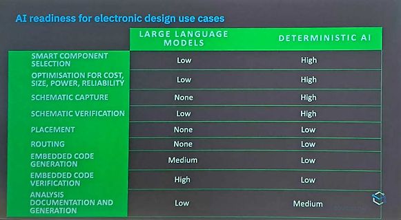
readiness for electronic design use cases LARGE LANGUAGE MODELS DETERMINISTIC AI SMART COMPONENT SELECTION Low High OPTIMISATION FOR COST, SIZE, POWER, RELIABILITY Low High SCHEMATIC CAPTURE None High SCHEMATIC VERIFICATION Low High PLACEMENT None Low ROUTING None Low EMBEDDED CODE GENERATION Medium Low EMBEDDED CODE VERIFICATION High Low ANALYSIS DOCUMENTATION AND GENERATION Low Medium
-
Thread
EMV-Problem Leitungsgebundene Störungen unterdrücken
eingezeichnet, durch ein IGBT ersetzt worden. Dies plane ich ein, weil die Freilaufdiode in den LowEMI-IGBTs offenbar besonders "weich" sind (die verbesserten EMV-Eigenschaften der LowEMI-IGBTs sind wohl vor allem auf die verbesserte Freilaufdiode zurückzuführen). Wir hatten, weil beim EMV-Dienstleister
allein schon hochohmig genug ;-) >>> Bei dieser Messung hatten wir schon auf einen LowEMI-IGBT gewechselt >> Was soll denn das sein? > Mit Low EMI wird ein Reiohe von IGBTs bei infieon ausgezeichnet, lt. > Disti-Support > "wird die EMI durch die Weichheit der Diode beeinflusst"
-
 Bild
Screenshot einer AVR-Programmierung und Fehlermeldung
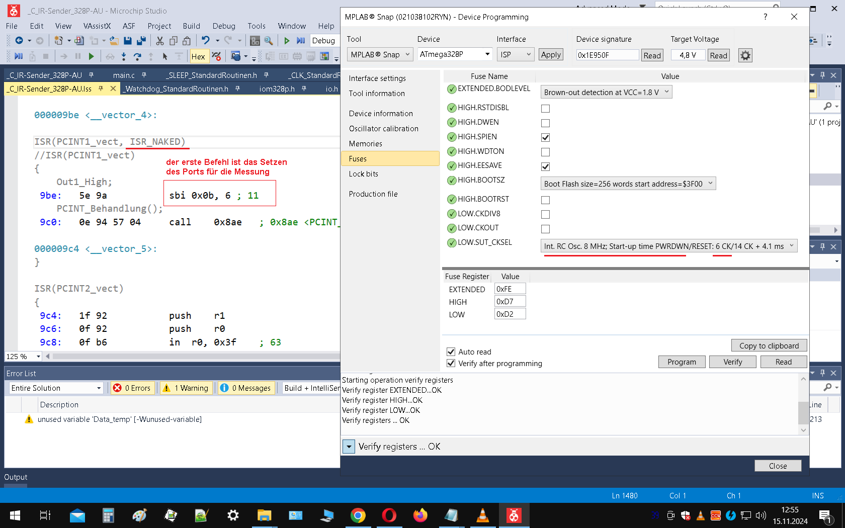
MPLAB Snap Atmel ATmega328P Brown-out detection at VCC = 1.8 V Fuse Register Value EXTENDED 0xFE HIGH 0xD7 LOW 0xD2 Error List 0 Errors 1 Warning 0 Message
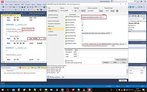
-
 Bild
Software-Screenshot der MPLAB Snap Device Programming Oberfläche
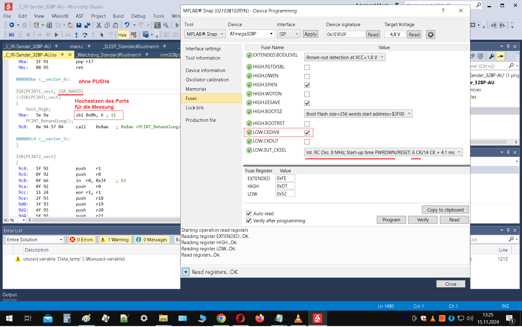
MPLAB® Snap, ATmega32P, Device Programming, Brown-out detection disabled, Fuses, HIGH.EXTENDED.BODLEVEL, HIGH.DWEN, HIGH.SPIEN, HIGH.WDTON, HIGH.EASAVE, HIGH.BOOTSZ, HIGH.BOOTRST, LOW.CKDIV8, LOW.CKOUT, LOW.SUT_CKSEL, Fuse Register, EXTENDED 0xFF, HIGH 0x07, LOW 0xD2
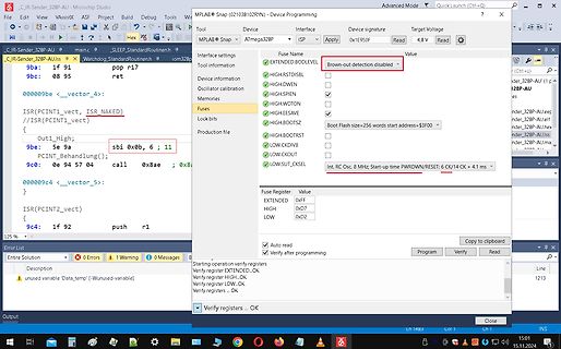
-
 Bild
Screenshot einer Mikrocontroller-Programmier-Software
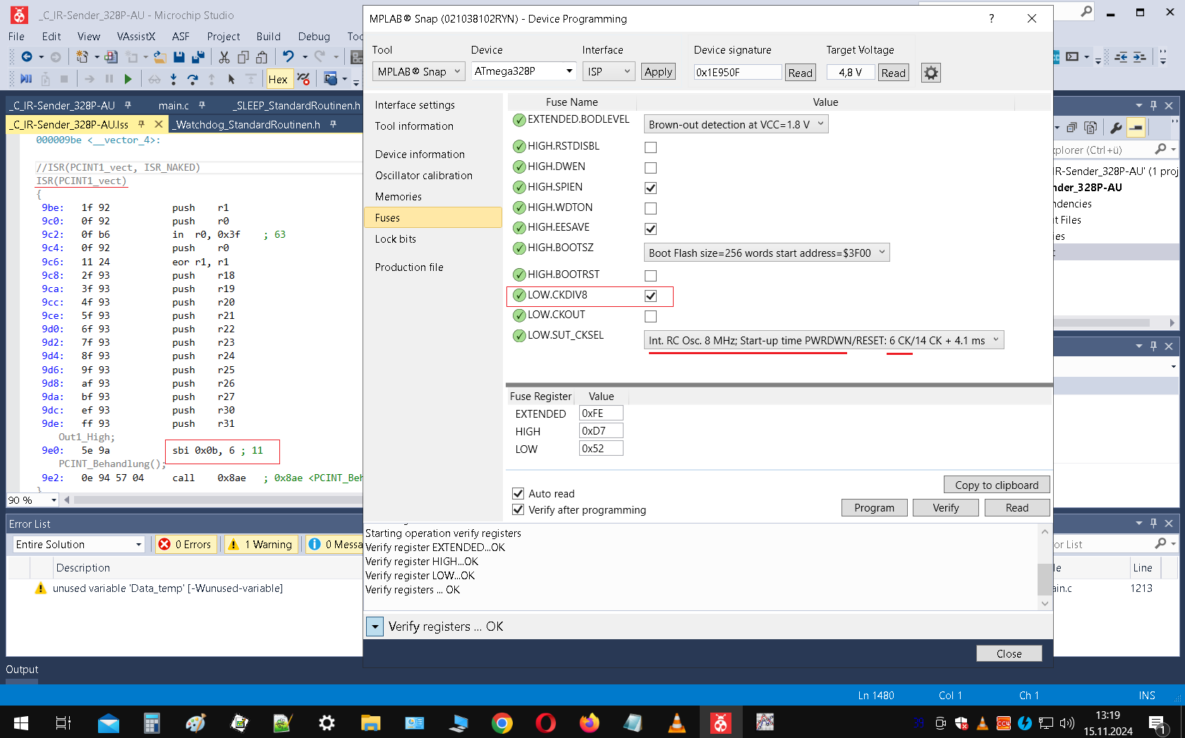
Debug Tool Apply 0x1E950F 4,8 V Read Hex Fuses EXTENDED: BOOLEVEL Brown-out detection at VCC = 1.8 V HIGH: DSTOSLB LOW: CKDIV8 LOW: SUT_CKSEL RC 8 MHz; Start-up time PWRDWN/RESET: 6 CLK / 14 CK + 4.1 ms ISR(PCINT1_vect) { sbi 0xb, 6 ; 11 9be: 5e 9a PCINT_Behandlung(); 9c0: 0a 94 57 04 call 0x8ae ; 0x8ae
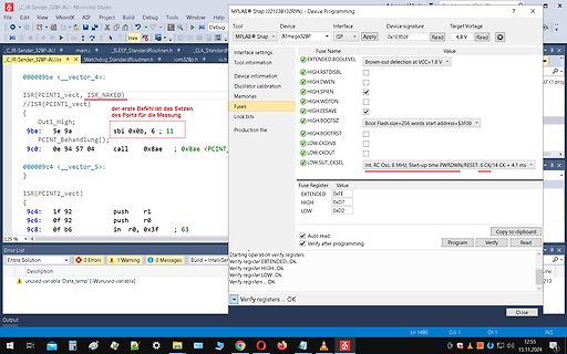
-
 Bild
Screenshot der MPLAB Snap Software zur Mikrocontroller-Programmierung
ATmega328P Interface: ISP Target Voltage: 4,8 V Hex Fuse Interface settings Fuse Name: EXTENDED, BODLEVEL, HIGH, SPIEN, WOTON, EESAVE, BOOTSZ, LOW, CKOUT, LOW.SUT, CKSEL Error List 0 Errors, 1 Warning, 0 Messages
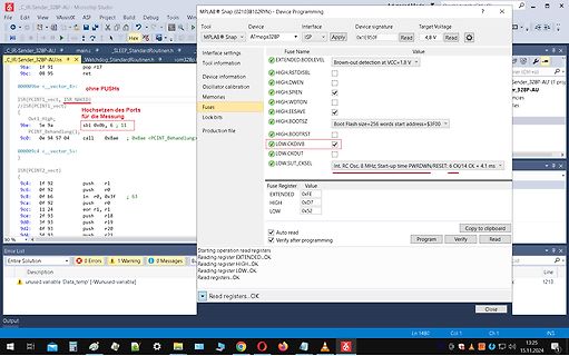
-
 Bild
MPLAB Snap Software mit AVR Fuse Einstellungen
MPLAB Snap, ATmega32BP, Fuse Name, Value, EXTENDED, HIGH, LOW, CKOUT, CKDIV8, Program, Verify, Read
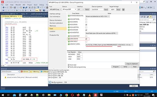
-
 Bild
Screenshot der MPLAB Software zur Mikrocontroller-Programmierung
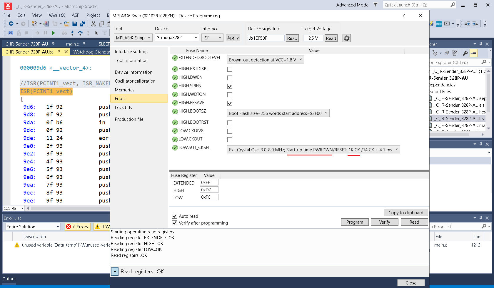
signature, Target Voltage, Read, AVR, C_JIR_Sender_32BP_AU, ISR(PCINT1_vect), Fuse, EXTENDED, BOOTLED, HIGH.RSTDISBL, HIGH.DWEN, HIGH.SPIEN, HIGH.WDTON, HIGH.BOOTSZ, LOW.CKDIV8, LOW.CKOUT, LOW.SUT_CSKEL, Fuse Register, EXTENDED 0xfe, HIGH 0xD7, LOW 0xFC, Error List, 0 Errors, 1 W, Reading register EXTENDED...OK, Reading register HIGH...OK, Reading register LOW...OK, Read registers...OK
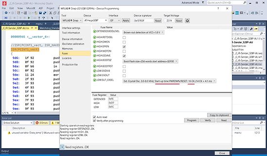
-
Thread
Electronica 2024, Tag 3 – Messtechnik und mehr
der in der Schweiz ansässigen AnaPico erweitert man das hauseigene Messtechnik-Portfolio um einige Low-End-Produkte. Außerdem gibt es im Bereich der portablen FieldFox-Produkte Erweiterungen mit höherer und niederer Grenzfrequenz. 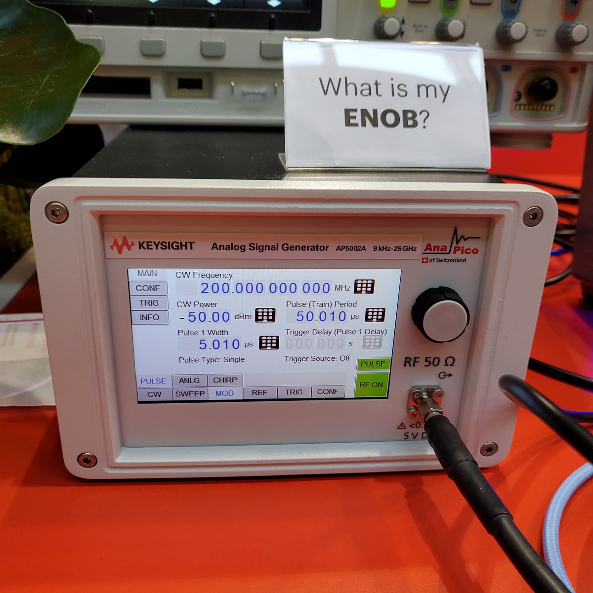 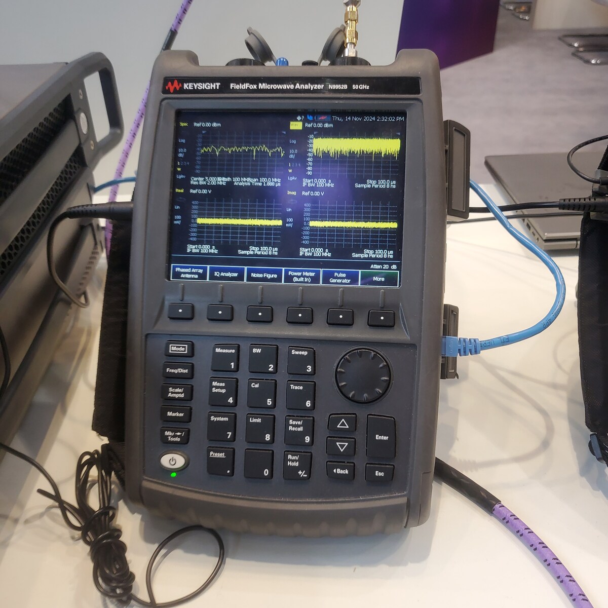
  ### Teledyne Lecroy – neue High End-Produkte Auf der electronica sind angeblich “vermögendere” Kunden als auf der EmbeddedWorld. LeCroy reagierte darauf mit dem Zeigen der hier angeteaserten Oszilloskopfamilie – der Einstiegspreis
-
 Bild
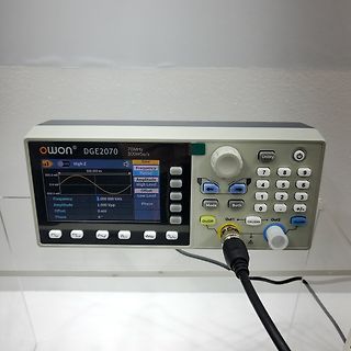
Owon DG2070 Funktionsgenerator
owon DG2070 70MHz 300MSa/s a1 High Z 333.333 us 500.0 mV 0.0 mV -500.0 mV Frequency 1.000 000 kHz Amplitude 1.000 Vpp Offset 0 mV Phase 0° Sine Frequency Period Amplitude High Level Offset Low Level Phase On/Off Out1 CH1/CH2 Out2 On/
-
 Bild
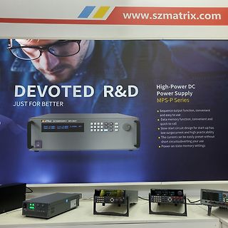
Werbebanner und verschiedene DC-Netzteile
www.szmatrix.com DEVOTED R&D JUST FOR BETTER High-Power DC Power Supply MPS-P Series Sequence output function, convenient and easy to use Data memory function, convenient and quick to call Slow start circuit design for start-up has low surcurrent and high practicability The current can be easily preset without Short circuitsubverting your use MPS-305P
-
Thread
Electronica 2024, Tag 2 – nRF54, ARM Cortex-M52 und mitdenkende LEDs
RAM (TCMRAM) for zero-wait execution of critical instructions and data. Additionally, they feature high-speed cache memory, with up to 2KB I-Cache and 512B D-Cache, further boosting core processing performance. --- via https://www.gigadevice.com/product/mcu/high-performance-mcus/gd32g5xx-series [/c]
®-M7 high-performance core with a frequency of up to 600 MHz. --- via https://www.gigadevice.com/about/news-and-event/news/gigadevice-launches-new-ethercat-subdevice-controller-chip [/c] ; pinMode(BLUE, OUTPUT); pinMode(WHITE, OUTPUT); digitalWrite(RED, LOW); digitalWrite(GREEN, LOW); digitalWrite(BLUE, LOW); digitalWrite(WHITE, LOW); } // define variables int redValue; int greenValue; int blueValue; int whiteValue; // main loop void
-
Thread
ESP32: Remapping der SPI-Pins "on the fly"
den Mode der einzelnen Ausgangspins (MOSI, SCK und CS) auf Output gestellt werden, aber nicht auf HIGH oder LOW festgelegt werden. pinMode(TOUCH_MOSI, OUTPUT); u.s.w. SPI.begin(TFT_SCK, TFT_MISO, TFT_MOSI, TFT_CS); SPI.beginTransaction(SPISettings(6000000, MSBFIRST, SPI_MODE0)); Soll nun
-
Thread
RS-Flipflop mit mehreren Eingängen
irgendwie sein kann. Und da soll als Folge davon, dass ein Komparator umgeschaltet hat, möglichst schnell High/Low-Mosfet umgeschaltet werden. Keine Zeit um noch auf irgendeinen Takt zu warten. Gruß, Roland
-
 Bild
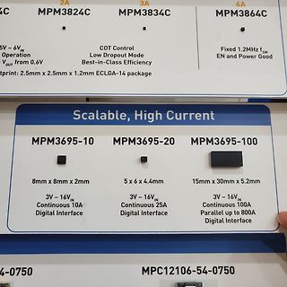
Werbeaufsteller für MPM-Leistungsregler
2A MPM3824C 3A MPM3834C 6A MPM3864C COT Control Low Dropout Mode Best-in-Class Efficiency Fixed 1.2MHz fsw EN and Power Good Scalable, High Current MPM3695-10 MPM3695-20 MPM3695-100 8mm x 8mm x 2mm 3V - 16VIN Continuous 10A Digital Interface 5 x 6 x
-
 Bild
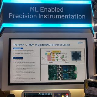
Präsentation eines Analog Devices SMU Referenzdesigns
multiple force/measure voltage ranges +/- 50V force & clamp resolution (lowest current range) 1 uV measure resolution (not at full range) The ranges could change depending on customer requirements 6x force/measure current ranges xA, xmA, xuA, xnA 20 uA force & clamp resolution (lowest current range) 5 pA measure resolution Pulsed operation 100W output power Automatic power supply adjustment for each voltage range Dual FMC (FPGA Mezzanine Card) form-factor AD3552R AD4310-24 ADH4710
-
 Bild
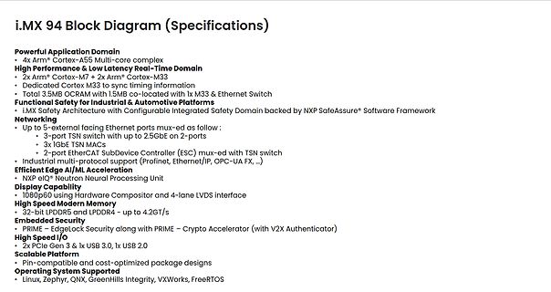
Spezifikationen i.MX 94 Blockdiagramm
Block Diagram (Specifications) Powerful Application Domain • 4x Arm® Cortex-A55 Multi-core complex High Performance & Low Latency Real-Time Domain • 2x Arm® Cortex-M7 + 2x Arm® Cortex-M33 • Dedicated Cortex M33 to sync timing information • Total 3.5MB OCRAM with 1.5MB co-located with 1x M33 & Ethernet
-
 Bild
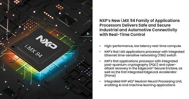
NXP i.MX 94 Prozessor auf Leiterplatte
Processors Delivers Safe and Secure Industrial and Automotive Connectivity with Real-Time Control High-performance, low latency real-time compute NXP's first i.MX applications processor with integrated Ethernet time-sensitive networking (TSN) switch NXP's first applications processor with integrated