-
Bild
Schraubendreher-Set und Elektrolytkondensatoren auf Holzuntergrund
1,2 mm 1,8 mm 2,4 mm 3 mm 3,5 mm 16 V 220 uFD 220 uFD 16 V 220 uFD 16 V 220 uFD 16 V 220 uFD 16 V 220 uFD
in „(V) Bastelmaterial 2“ · Markt · · Fotos
-
Bild
Rückseite eines BBC Oscilloscope Typ M6011
240 220 BBC Oscilloscope Type: M6011 D-0500 Number: 60 AC 50 60Hz 110V T 0.63A 220V T 0.315A 240V Watts (max.) 46 Power Fuse IEC to 6.3x25mm X-Rays Dose Equivalent Rate <3pA/kg Watts to Work Density Fabrique en RFA
in „[V] BBC M 6011, Baugleich Hameg 208 Speicheroszilloskop“ · Markt · · Fotos
-
Bild
Schaltplan und Frequenzgang eines Filters
Mixer Elektor 11 anpassen, -40%, 480Hz Schlanker Tief zu Hoch, Mitte, Tief 45-54 C 15n Mitte 31-68 c4 10 C 15n Hoch 15-95 C28c3 3n3.asc V(out) V(out2) R10 470k R13 10k R14 10k C4 10n R2 1K R1 10K U1 TL071 U2 TL071 C1 15n R7 74k R6 3.3k R5 3.3k C2 3.3n C3 22k R3 10K R16 10K R15 10K U3 TL071 R24 3.3k R27 3.3k R26 10K R28 10K C10 15n C5 15n R17 3.3k R19 6.4k R20 3.3k C6 15n R18 10K U4 TL071 C7 10n C8 3.3n R21 10K R22 3.3k R23 3.3k R25 10K C9 10n
in „Probleme bei Entwicklung von Analogem DJ Mixer“ · Analoge Elektronik und Schaltungstechnik · · Screenshots
-
Bild
Edelstahlbackofen mit eingeschaltetem Licht
d003b9c7-e286-4147-813b-ebf6f321316d.jpg
in „Backofentür zertrümmert-Alte Sichtscheibe geht nicht raus“ · Haus & Smart Home · · Fotos
-
Bild
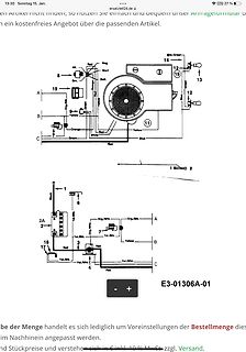
Verdrahtungsplan oder Anschlussbelegung
kostenfreies Angebot über die passenden Artikel. 8 Alt. Red Mag Start 14 12 15 13 Green 19 Orange Blue 12 A B 9 Yellow 11 B Yellow C Orange Red White Blue Green Red 1 Black 6 2A Org/Wht. A Org/Wht. 2 Yel/Wh. 7 Org/Bkt. B Yel/Blk. 18 3 Yel/Blk. B 17 Red Red Yellow C 4 Yel/Wh. Red C 4 Yel/Blk. E3-01306A-01 be
in „RasenTraktor licht. 12V AC?“ · Fahrzeugelektronik · · Schaltpläne
-
Bild
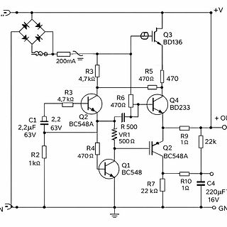
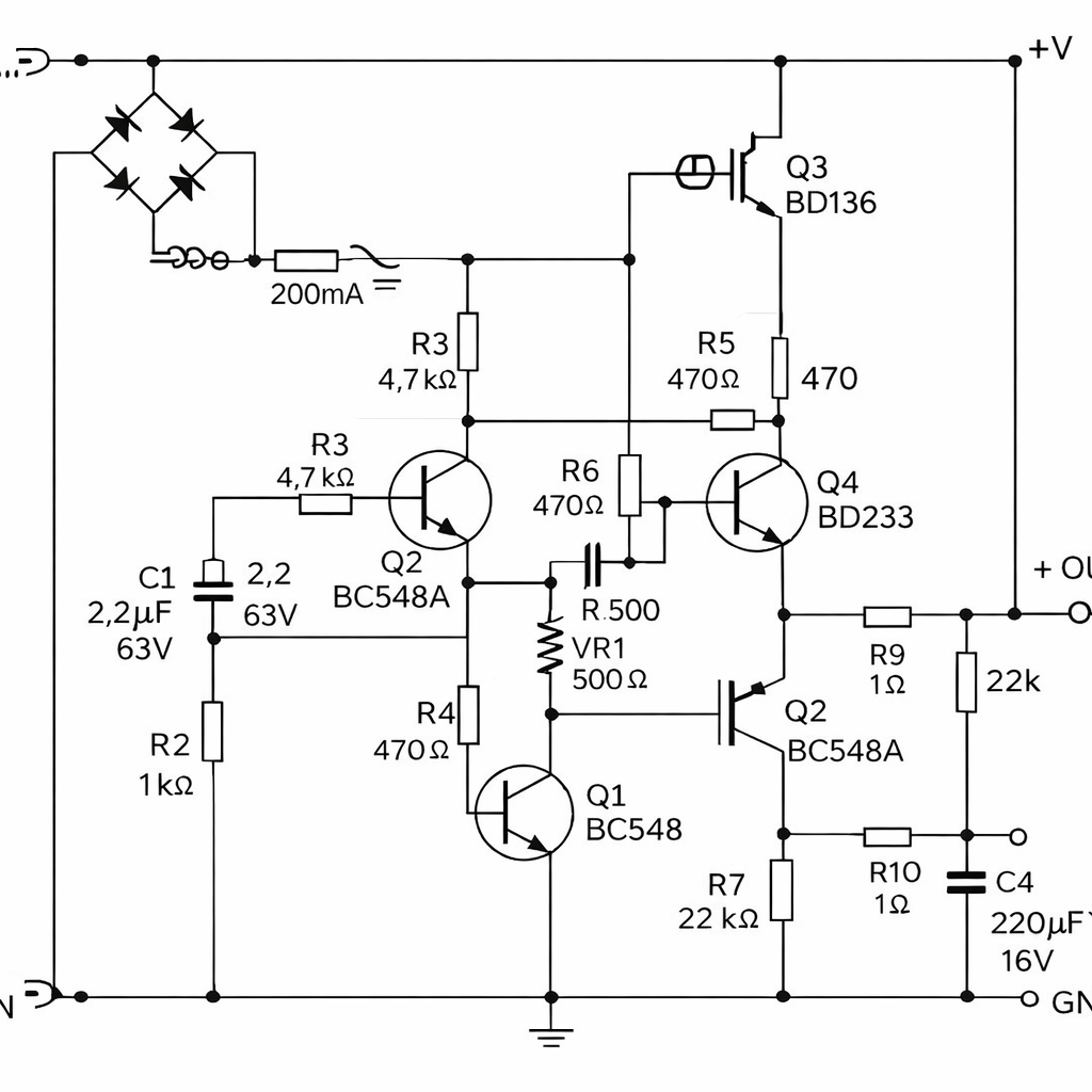
Schaltplan einer Transistorregelung
+V Q3 BD136 200mA R3 4,7 kΩ R5 470 470 R6 470 Ω Q4 BD233 R3 4,7 kΩ Q2 BC548A C1 2,2 µF 63V R2 1 kΩ R4 470 Ω VR1 500 Ω Q1 BC548 R9 1 Ω 22k + OUT Q2 BC548A R10 1 Ω C4 220 µF 16V R7 22 kΩ GND
in „Orgel Ora P21 bzw. Ingrid Orgel“ · Analoge Elektronik und Schaltungstechnik · · Schaltpläne
-
Bild
Nahaufnahme einer bestückten Leiterplatte mit Schraubklemmen
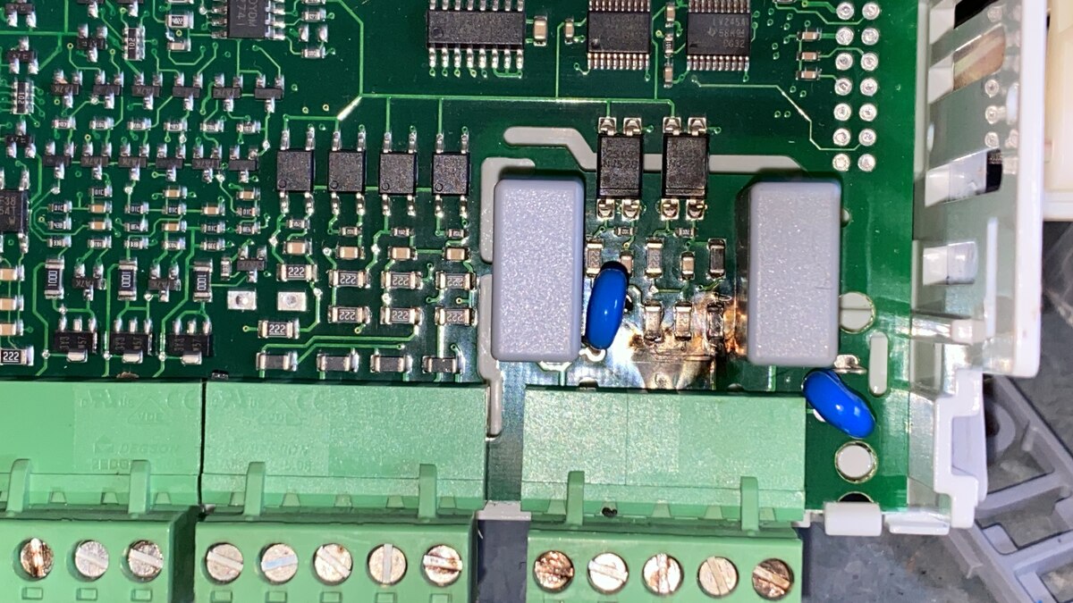
222, 101, 101, 222, 222, 222, 222
in „Wasser zu Wasser Wärmepumpe - Platine defekt - Ersatzteile / Reparatur - Artikelnummer BUDERUS-7747“ · Analoge Elektronik und Schaltungstechnik · · Platinenfotos
-
Bild
Oszilloskop-Messung digitaler Signale
Agilent Technologies MON APR 08 16:44:26 2024 1 2.00V/ 2 2.00V/ 3 2.00V/ 4 2.00V/ 36.80µs 20.00µs/ Stop 1 4 1.85V Save to file = jtag06 Save Recall Default Setup Press to Save Quick Print
in „Atmel JTAG ICE mk-II RSP_ILLEGAL_JTAG_ID“ · Mikrocontroller und Digitale Elektronik · · Oszi-Bilder
-
Bild
Detailaufnahme einer bestückten Leiterplatte mit Flachbandkabeln
MC6809P, MC6809EP, MC6809, TIMER, VOICE ROM, ROM, ROM,
in „a Microprocessor for the Revolution -- 6809“ · Mikrocontroller und Digitale Elektronik · · Platinenfotos
-
Bild
HP Server RAID Controller Karte
4K1355 SN: AU228PC2018 R PN: 631687-021 N20YP3 CN: CN7390098 PN: 631687-021 7454801112613 16SAS500143B0284F6D00 SN: SR39CP2442 R
in „Fragen zu PC-Karten“ · PC Hard- und Software · · Platinenfotos
-
Bild
Leuchtende LEDs auf einem Breadboard mit Krokodilklemmen
c d e f g h i j k l m n o p q r s t u v w x y z +
in „Zweifarbiges LED ansteuern“ · Analoge Elektronik und Schaltungstechnik · · Fotos
-
Bild
Solid State Relay 25A AC-12
24-480VAC Open 24-480VAC Close -KB35DA CE 25A AC-12 SOLID STATE RELAY 3-32VDC
in „REX PID Temperaturregler: 2 Verbraucher ABWECHSELND schalten“ · Mikrocontroller und Digitale Elektronik · · Fotos
-
Bild
3D-Rendering eines elektronischen Bauteils
DCJ250_20_B_K1_A.jpg
in „[S] DCJ250-20-B-K1-A 4x“ · Markt · · Fotos
-
Bild
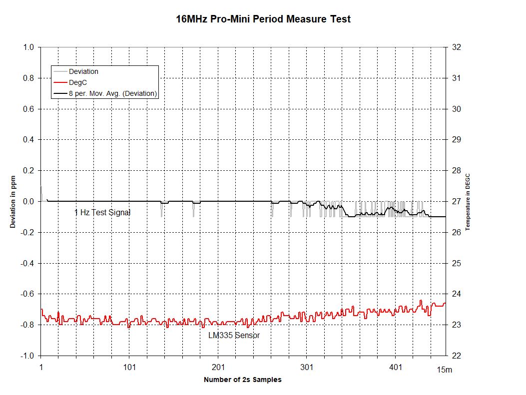
Diagramm einer Periodenmessung mit Temperaturverlauf
16MHz Pro-Mini Period Measure Test Deviation DegC 8 per. Mov. Avg. (Deviation) 1.0 0.8 0.6 0.4 0.2 0.0 -0.2 -0.4 -0.6 -0.8 -1.0 1 101 201 301 401 15m Deviation in ppm 32 31 30 29 28 27 26 25 24 23 22 Temperature in DEGC 1 Hz Test Signal LM335 Sensor Number of 2s Samples
in „AVR T1 Capture Problem - Meinung erbeten“ · Mikrocontroller und Digitale Elektronik · · Diagramme
-
Bild
Zwei grüne Leiterplatten mit LMX2594 Bestückungsdruck
3073161A, T10-210725 6 mil JLCPCB 4 layer DK4XP 1 Top LMX2594 12 mil JLCPCB 4 layer DK4XP 1 Top LMX2594
in „JLCPCB - additional charge“ · Platinen · · Platinenfotos
-
Bild
Elektronikplatine in Metallgehäuse
0594 0041 FRONT CE 201 R207 REMOVE SEAL AFTER WASHING D205 C210 T221 R228 R227 R230 R232 R233 R234 R231 R235 C209 R201 C228 C226 LAA110P LI XYS 1430T63893 94V0 R205 22822 32 14 S201 R237 R238 R236 R239 R201 D201 4.999.138.060 693 046 SW.5.1.2 SNr. 15055 0070
in „Analoges Telefon über TA an ISDN-Anlage in Seniorenheim“ · Haus & Smart Home · · Platinenfotos
-
Bild
Frequenzspektrum Messungen
So 17. Jan 15:56:54 CET 2016 created by user "gerhard" on machine "precision" 10 dB/div 0dB = 1nV/sqrt Hz 'bzx84C2v7_z12.tra' 'bzx84C3v3_Z14_3.54Vactual.tra' 'bzx84C4v7_Z1_4.9Vactual.tra' 'bzx84C6V8_Zsp_NXP.tra' 'bzy85C3V3_TFK_old_glassdiode.tra' 'LM399_HeaterUnpowered.tra' 'ln4151_
in „Low Noise Netzteil?“ · Analoge Elektronik und Schaltungstechnik · · Oszi-Bilder
-
Bild
Zwei weiße Kunststoff-Steckverbinder mit Metallstiften
BM03B-GHS-TBT_LF__SN_.jpg
in „Steckertyp erkennen“ · Mikrocontroller und Digitale Elektronik · · Fotos
-
Bild
Selbstbau-Netzteil mit Elektrolytkondensatoren und Gehäuse
35 3300 uF 63V BJT-FET 2.5V CLEAR THE LINUX PROGRAMMING INTERFACE
in „moderner Ersatztyp für BC550 Audio low noise gesucht“ · Analoge Elektronik und Schaltungstechnik · · Platinenfotos
-
Bild
SPICE-Simulation einer Trioden-Kennlinie
6C33C-0_kennlinie_03.asc ix(U1,Plate) 1.00A 0.95A 0.90A 0.85A 0.80A 0.75A 0.70A 0.65A 0.60A 0.55A 0.50A 0.45A 0.40A 0.35A 0.30A 0.25A 0.20A 0.15A 0.10A 0.05A 0.00A Legend V2-0 (Run: 1/11) V2-20 (Run: 3/11) V2-40 (Run: 5/11) V2-50 (Run: 6/11) V2-60 (Run: 7/11) V2-70 (Run: 8/11) V2-80 (Run: 9/11) V2-90 (Run: 10/11) V2-100 (Run: 11/11) 40V 80V 120V 160V 200V 240V 280V 320V V1 U1 V2 6C33C .include Triodes.sub .dc v1 0 350 1 v2 0 100 10
in „innenwiderstand Röhrenmodell mit ltspice ermitteln“ · Analoge Elektronik und Schaltungstechnik · · Screenshots
-
Bild
Schaltplan CH32V003 mit HT16K33A und 7-Segment-Anzeige
Digit 7-Segmentanzeige ( CH32V003 μC mit HT16K33A ) 3641AH gemeinsame Kathode DIG3 DIG2 DIG1 DIG0 a b c d e f g DP com3 com2 com1 com0 25 24 23 22 21 20 19 18 5 4 3 2 ROW0 ROW1 ROW2 ROW3 ROW4 ROW5 ROW6 ROW7 +5V 100n 10µ 2,2k 2,2k CH32V003F4P6 PA1 PA2 SDA SCL HT16K33A-SSOP28 SWIO PD1 / SWIO 9 27 26 18
in „HT16K33A mit CH32V003“ · Projekte & Code · · Schaltpläne
-
Bild
Steckdosenleiste mit USB-Anschlüssen
ROOTOMA QC 3.0 PD 20W
in „Asymmetrischer Reiseadapter Schweiz ohne Sicherung“ · Haus & Smart Home · · Fotos
-
Bild
Oszilloskop-Screenshot einer RS232 UART Signalkurve
Fl. Auto Wellenform 64 von 64 Instrumente Automatische Einrichtung Öffnen Speichern Drucken Voll A B DC x1 ±10 V Gen Aus RS232 / UART - Ch B Weitere... Ansichten Messungen Rechenkanäle DeepMeasure Serielle Entschlüsselung Referenz-wellenformen Masken Lineale Vorgänge 0,0 ms 1,0 2,0 3,0 4,0 5,0 6,0 7,0
in „RS485 Pegelunterschiede“ · Mikrocontroller und Digitale Elektronik · · Oszi-Bilder
-
Datei
AVRStrudio4.11b401_Release_Notes.txt
Release Note Welcome to AVR Studio 4.11 (01/2005) What's new in this release... Debug platform updates New firmware and part upgrade. Please refer to the JTAGICE mk II help for more information New firmware and part upgrade. Please refer to the ICE 50 help for more information Programming support updates A new major version (V2) of the STK500 firmware is released with this version of AVR Studio. Along with this, the protocol and driver for the STK500 has been updated. Please refer to the STK500 and AVRISP help for more information. A separate programming platform connection dialog gives more control
in „AVRStudio4 v4.11 Build 401 Beta freigegeben“ · Mikrocontroller und Digitale Elektronik ·
-
PDF
hitachi_hb28b128mm2.pdf
HB28E016MM2/HB28D032MM2 HB28D064MM2/HB28B128MM2 MultiMediaCard 16 MByte/32 MByte/64 MByte/128 MByte ADE-203-1294C (Z) Rev. 3.0 Apr. 26, 2002 Description These Hitachi MultiMediaCard s, HB28E016MM2, HB28D032MM2, HB28D064MM2 and HB28B128MM2, are
in „0x40 und 0x95 in SD/MMC-Karte“ · Mikrocontroller und Digitale Elektronik ·
-
Datei
RFID_Tiny2313_U2770B_stripped.txt
RFID-Bausatz, ArtNr:810059 ' Es dient zum Auslesen einer HITAG RFID-Karte mittels eines Atmel U2270B. ' Âusschnitte des Codes wurden von der Beispielsoftware für den Em4095 von ' www.mcselec.de übernommen und für den U2270B abgeändert ' Als Controller wird ein AT-Tiny 2313 verwendet. '--------------
in „BASCOM Programm nach C übersetzen“ · Mikrocontroller und Digitale Elektronik ·
-
PDF
Tasten_LCD_V1.1_b2_.pdf
. 3EL O- TNUOM 4H DNG . 3EL O- TNUOM V5+ 3H 1 1$P 2 SR 2$P 3 DNG DR 3$P 4 NE 4$P 5 5$P 6 0BD 6$P R 2 1BD 7$P 7 2 R 2BD 8$P 8 TNOC3BD 9$P 9 4BD 01$P 01 5 CCV 5BD DNG 11$P 11 V 6BD 21$P 21 DNG 7BD 31$P 31 41$P 41 DNG 1DCL DEL C261DCL T 3 S 1 R022 a 4 1 2 e 5R 9 3 3 2 1 R022 K 7 4 2 R74 H 4R 1C 1 S R022 A m 3 3 1 9R n074 m 4 2 3R R022 + 3 4 1 V 4 2 1R 2. 3EL - TNUOM . 3EL O- TNUOM 2H 1H
in „LCD Display an Mikrocontrollerschaltung“ · Mikrocontroller und Digitale Elektronik ·
-
Datei
ettft240320tp3_2_rev_b.c
********************************************************************/ #ifndef ETTFT240320TP3_2_REV_B_C #define ETTFT240320TP3_2_REV_B_C // interne Header #include <stdio.h> // Standard I/O-Funktionen (printf, ...) #include <stdlib.h> // Deklariert ISO C-Makros/Funktionen & AVR-spezifische Erweiterungen
in „ET-TFT320240 Rev.3.2 Code in Modul und Header aufteilen“ · Mikrocontroller und Digitale Elektronik ·
-
Datei
ettft240320tp3_2_rev_b.h
************************************************* * * * Header für Display "ET-TFT240320 TP3.2 Rev.b" * * * **************************************************************************************************/ #ifndef ETTFT240320TP3_2_REV_B_H #define ETTFT240320TP3_2_REV_B_H // Farb Konstanten #define
in „ET-TFT320240 Rev.3.2 Code in Modul und Header aufteilen“ · Mikrocontroller und Digitale Elektronik ·
-
PDF
122855-da-01-de-OSZILLOSKOP_TDS2004B.pdf
OpenChoice -PC-Kommunikationssoftware. Technische Daten Digitalspeicher-Oszilloskope der Serie TDS1000B und TDS2000B TDS1001B TDS1002B TDS1012B TDS2002B TDS2004B TDS2012B TDS2014B TDS2022B TDS2024B Anzeige Mono Mono Mono Farbe Farbe Farbe Farbe Farbe Farbe (1/4 VGA-LCD) *2 Bandbreite 40 MHz 60 MHz 100
in „Digitalspeicher-Oszilloskop“ · Mikrocontroller und Digitale Elektronik ·
-
PDF
hitachi_hb28b128mm2.pdf
HB28E016MM2/HB28D032MM2 HB28D064MM2/HB28B128MM2 MultiMediaCard 16 MByte/32 MByte/64 MByte/128 MByte ADE-203-1294C (Z) Rev. 3.0 Apr. 26, 2002 Description These Hitachi MultiMediaCard s, HB28E016MM2, HB28D032MM2, HB28D064MM2 and HB28B128MM2, are
in „MMC oder SD card connector zum 8515“ · Projekte & Code ·
-
PDF
L293B_L293E_STM.pdf
0.100 e3 17.78 0.700 F 7.1 0.280 i 5.1 0.201 L 3.3 0.130 Z 1.27 0.050 a I b1 L b B e E Z e3 D P . 16 9 1 D F P 1 8 10/12 L293B - L293E POWERDIP (16+2+2) PACKAGE MECHANICAL DATA Dimensions Millimeters Inches Min. Typ. Max. Min. Typ. Max. a1 0.51 0.020 B 0.85 1.4 0.033 0.055 b 0.5 0.020 b1 0.38 0.5 0.015 0.020 T D 24.8 0.976 W 2 E 8.8 0.346 D e 2.54 0.100 e3 22.86 0.900 F 7.1 0.280 i 5.1 0.201 L 3.3 0.130 Z 1.27 0.050 a I L b1 b B e E Z e3 Z D S E 20 11 0 I F M P 1 10 11/12 L293B - L293E
in „Wie Stromstitzen unterdrücken?“ · Mikrocontroller und Digitale Elektronik ·
-
Bild
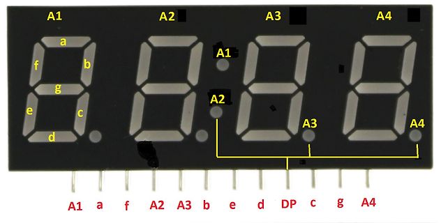
Beschriftung einer 4-stelligen 7-Segment-Anzeige
A1 A2 A3 A4 a b c d e f g A1 A2 A3 A4 A1 a f A2 A3 b e d DP c g A4
in „Pollin LED-Anzeige 4HSG21010B26-1W 10mm grün 4 digit“ · Analoge Elektronik und Schaltungstechnik · · Fotos
-
PDF
GPG320X240-NFNDSCW3_B_.pdf
2.0 1 0.08<Φ — 0 ◎ When the width is over 0.08 mm, according to the (Ⅰ) Circle Spots. (Ⅲ) a≦X/2 and b≦X/2, but not be allowed short. X a b ◎ Follow the above defect quantity≦4 Defects. Grand Pacific Optoelectronics Corp. GPG320X240- NFNDSCW3 (Vers. B) Page 20 /23 8.3.2 Cosmetic Characteristics No Item
-
PDF
cy7b135-35lmb_407325.pdf
-
Datei
owdevice_ATT13_DS18B20.c
lwmode; bytep=lbytep; bitp=lbitp; srcount=lsrcount; actbit=lactbit; scrc=lscrc; #ifdef _DB_ // dbbuf[b1]=lmode;b1++; #endif } int main(void) { mode=OWM_SLEEP; wmode=OWW_NO_WRITE; OW_DDR&=~OW_PINN; MCUCR=(1<<ISC00); //Any logical change #ifdef __AVR_ATtiny13A__ CLKPR=0; //9.6Mhz DDRB|=(1<<PORTB4);//DEBUG PORT PORTB|=(1<<PORTB4); TIMSK0=0; GIMSK=(1<<PCIE); PCMSK=(1<<PCINT3); #endif TCNT1=0x0; TCCR0B=(1<<CS00)|(1<<CS01); //9.6mhz /64 wegen 8 bit Timer also aller 6,666us DIS_TIMER; EN_OWINT; sei(); DDRB&=~(1<<PINB2); ADMUX=(1<<MUX0); ADCSRA= (1<<ADEN) | (1<<ADPS2) | (1<<ADPS1) | (1<<ADPS0); while(
in „1-Wire Slave auf AVR“ · Mikrocontroller und Digitale Elektronik ·
-
Datei
owdevice_ATT13_DS18B20.c
AVR_ATmega32__ GICR|=(1<<INT0); TCCR1B=0x00; TCCR1B|=(1<<CS11); //Systemtackt durch 8 also 1 us TCNT1=0; DDRA&=~(1<<PINA0); ADMUX=(1<<REFS0); ADCSRA= (1<<ADEN) | (1<<ADPS2) | (1<<ADPS1) | (1<<ADPS0); b1=b2=0; init_uart0(0); uart_puts("\nHallo\n"); char s[16]; b1=b2=0; DDRD|=(1<<PIND4); PORTD|=(1<<PORTD4); DDRD|=(1<<PIND3); PORTD|=(1<<PORTD3); EN_OWINT; #endif DIS_TIMER; sei(); while(1){ #ifdef __AVR_ATmega32__ while(b1!=b2) { /*switch (dbbuf[b2]) { case OWM_SLEEP
in „1-Wire Slave auf AVR“ · Mikrocontroller und Digitale Elektronik ·
-
Datei
owdevice_ATT13_DS18B20.c
\n"); char s[16]; b1=b2=0; DDRD|=(1<<PIND4); PORTD|=(1<<PORTD4); DDRD|=(1<<PIND3); PORTD|=(1<<PORTD3); EN_OWINT; #endif DIS_TIMER; sei(); while(1){ #ifdef __AVR_ATmega32__ while(b1!=b2) { uart_puts(utoa(dbbuf[b2],s,16));uart_puts(" "); b2++; } #endif } }
in „1-Wire Slave auf AVR“ · Mikrocontroller und Digitale Elektronik ·
-
Datei
DS18B20_Multiplexer_go1.bas
$regfile = "m32def.dat" $crystal = 16000000 $swstack = 50 $hwstack = 50 $framesize = 50 Config Lcdpin = Pin , Db4 = Portc.4 , Db5 = Portc.5 , Db6 = Portc.6 , _ Db7 = Portc.7 , E = Portc.3 , Rs = Portc.2 Config Lcd = 16 * 4 Cls Cursor Off '=============================================================================== '=============================================================================== '=========================== Variablendeklaration ============================== Dim Sp1 As Integer 'Integer für Scratchpadinhalt Dim Sp2 As Integer Dim Sp3 As Integer Dim Sp4 As Integer Dim Temp1 As
in „DS18B20 multiplexen“ · Mikrocontroller und Digitale Elektronik ·
-
Datei
DS18B20_Multiplexer_go2.bas
$regfile = "m32def.dat" $crystal = 16000000 $swstack = 50 $hwstack = 50 $framesize = 50 Config Lcdpin = Pin , Db4 = Portc.4 , Db5 = Portc.5 , Db6 = Portc.6 , _ Db7 = Portc.7 , E = Portc.3 , Rs = Portc.2 Config Lcd = 16 * 4 Cls Cursor Off '=============================================================================== '=============================================================================== '========================== Variablendeklaration =============================== Dim Sp1(9) As Byte 'Array für Scratchpadinhalt Dim Sp2(9) As Byte Dim Sp3(9) As Byte Dim Sp4(9) As Byte Dim Tmp1 As Byte
in „DS18B20 multiplexen“ · Mikrocontroller und Digitale Elektronik ·
-
PDF
471D81B8d01.pdf
XTAL1/TOSC1) PB6 7 18 AVCC (XTAL2/TOSC2) PB7 8 17 PB5 (SCK) 9 1 1 1 1 1 1 16 5 6 7 0 1 2 3 4 D D D B B B B B ) ) P) ) P) ) ) ) T N N P 1A 1 C O ( A AI I C C / I ( ( ( ( / S ( S O ( ( MLF Top View ) ) C D T / / ) ) 0 ) ) E 5 4 3 2 T X X E D D D D ( ( ( R(A ( ( A( ( 2 1 0 6 5 4 3 2 P P P P P P P P 2 1
in „Motorregelung für Fußballroboter“ · Mikrocontroller und Digitale Elektronik ·
-
PDF
Torex_XC6210B332MR_-_LDO.pdf
SERIES 1 6 1 2 ⑤ ② 1 0 2 ⑥ ③ 5 XC6210xxxxxx 3Represents CE Function 3 4 MARK TYPE PRODUCT SERIES USP-6B A High Active With Pull-Down Resistor XC6210AxxxDx (TOP VIEW) B High Active With No Pull-Down Resistor XC6210AxxxDx C Low Active With Pull-Up Resistor XC6210AxxxDx D Low Active With No Pull-Up Resistor
in „Low-drop Torex 1V Dropout zu viel“ · Analoge Elektronik und Schaltungstechnik ·
-
PDF
hitachi_hb28b128mm2.pdf
HB28E016MM2/HB28D032MM2 HB28D064MM2/HB28B128MM2 MultiMediaCard 16 MByte/32 MByte/64 MByte/128 MByte ADE-203-1294C (Z) Rev. 3.0 Apr. 26, 2002 Description These Hitachi MultiMediaCard s, HB28E016MM2, HB28D032MM2, HB28D064MM2 and HB28B128MM2, are
in „MMC/SD SPI Mode Multi Block Write“ · Mikrocontroller und Digitale Elektronik ·
-
PDF
B400_10-HC49U-S.pdf
Technische Daten Betriebstemperaturbereich: -10...+60°C Frequenztoleranz (25°C): ±50ppm Parallelkapazität (Shunt capacitance), max.: 7pF Quarzbelastung: 1,0mW Isolationswiderstand (100V DC): >500MΩ Temperaturstabilität: ±50ppm Vibration mode (Schnitt): fundamental Alterung: ±5ppm/Jahr Type Frequenz C RESR [Hz] [pF] [Ω] QMIM003,579 3.579.545 16 150 QMIM003,686 3.686.000 16 150 QMIM004 4.000.000 30 150 QMIM004,096 4.096.000 30 150 QMIM004,194 4.194.304 32 150 QMIM004,433 4.433.619 16 150 QMIM004,915 4.915.200 16 150 QMIM005 5.000.000 30 150 QMIM006 6.000.000 30 150 QMIM006,144 6.144.000 16 100 QMIM007,372
in „Genaue Sekunde AVR“ · Mikrocontroller und Digitale Elektronik ·
-
PDF
DS_S6B1713_R42.pdf
1 -0.2%/°C S6B1713A15-B0CY (VDDconnected) 470 μm S6B1713A05-xxX0 0 670 μm S6B1713A05-xxXN (VSSconnected) -0.05%/°C 470 μm TCP S6B1713A15-xxX0 1 670 μm -0.2%/°C S6B1713A15-xxXN (VDDconnected) 470 μm * xx: TCP ordering
in „Frage zu static indicator glcd“ · Mikrocontroller und Digitale Elektronik ·
-
Bild
Blockschaltbild einer Bus-Matrix eines Mikrocontrollers
64-Kbyte CCM data RAM, ARM Cortex-M4F, GP DMA1, GP DMA2, MAC Ethernet, USB OTG HS, I-bus, D-bus, S-bus, DMA_PI, DMA_MEM1, DMA_MEM2, DMA_P2, ETHERNET_M, USB_HS_M, S0 bis S7, M0 bis M6, ICODE, DCODE, ACCEL, Flash memory, SRAM 112 Kbyte, SRAM 16 Kbyte, AHB periph 1, AHB periph 2, FSMC Static MemCtl, APB1, APB2, Bus matrix-S
in „Zugriff auf Hauptspeicher“ · Mikrocontroller und Digitale Elektronik · · Diagramme
-
PDF
rej09b0001_r8csm.pdf
position in bit. Figure 1.7.6 shows examples of how to specify bit 2 of address 0000A 16. Address b7 b0 0 n-1 n n+1 nÅ+1 n n–1 0 b7 b0b7 b0b7 b0 b7 b0 Memory map Bit map Figure 1.7.5 Relationship between Memory Map and Bit Map Address 0000A 16 b7 b2 b0 BSET 2,AH ; Address 00009 16 b15 b10 b8b7 b0 BSET
in „Assembler durchschnitts berechnung“ · Mikrocontroller und Digitale Elektronik ·
-
PDF
0900766b80db11a6.pdf
81 tuocso46 TUOCS O 6BP 71 2 + s M P c d d f 5 6 7 0 1 2 3 4 5 S F U U U U U V V P P P P P P P P P B B 2 . K C 4 R 1 F 1 2 3 4 5 6 7 8 9 0 2 3 4 5 6 2 4 0 1 1 1 1 1 1 1 2 C 1 E _ d e e U 1 V R Gl D C 0 u C + C 1 V u + C 1 n 9 0 C 2 R 1 8 R 1 1 6 5 8 n 1 R 1 C 4 1 2 3 4 5 B D n m + M P n D B 1 V D D
-
PDF
A500_EADIP180B-5NLW.pdf
9.2005 EA DIP180-5 LCD- GRAFIK MODUL 180x32 INKL. KONTROLLER SED1520 FÜR 8-BIT BUS ! ne u EADIP180B-5NLW Abmessungen 102 x 27 mm TECHNISCHE DATEN * KONTRASTREICHE LCD-SUPERTWIST ANZEIGE * BLAU-WEISS MIT STARKEM KONTRAST: EA DIP180B-5NLW * KONTROLLER SED1520, PT6520 ODER KOMPATIBEL INTEGRIERT * ANSCHLUSS
in „LCD Display EADIP180-5“ · Mikrocontroller und Digitale Elektronik ·
-
PDF
LCD_display_162b_series-v12.pdf
Filet’ 1. Lead parts all around the lead. Solder should not hide the lead form perfectly. (too much) b. Components side ( In case of ‘Through Hole PCB’ ) Solder to reach the Components side of PCB. 2. Flat packages Either ‘toe’ (A) or ‘heal’ (B) of Minor the lead to be covered by ‘Filet’. A B Lead form
in „C-Code für LCD-Display (Displaytech 162B)“ · Mikrocontroller und Digitale Elektronik ·