
-
Thread
Cooles chip von Efinix
Datenblatt. Auszug aus dem Datenblatt TI180: 10-kbit high-speed, embedded SRAM, configurable as single-port RAM, simple dual-port RAM, true dual-port RAM, or ROM LPDDR4/4x PHY (supporting x16 or x32 DQ widths) with memory controller hard IP Darunter verstehe ich das der Chip nur ein LPDDR4
-
 Bild
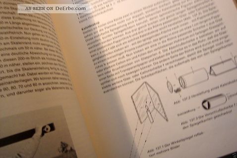
Foto einer Buchseite mit Anleitung und Zeichnungen
AS SEEN ON DeErbe.com Kaleidoskop Abb. 137.2 Herstellung eines Kaleidoskops Abb. 137.3 Die Verschlussscheibe Abb. 137.1 Der Winkelspiegel reflektiert mehrere Bilder
-
Thread
Ursachen von Überschwingungen und Unterschwingungen
merken: Das Gibb'sche Phänomen taucht nicht auf dem Scopeschirm > auf! Many instruments, such as high-speed scopes and even network analyzers, can be approximated as high order filters with a pole frequency and a filter order. Zitat aus https://www.signalintegrityjournal.com/articles/2175-how-to-avoid-gibbs-ringing-artifacts-in-measurements
-
 Bild
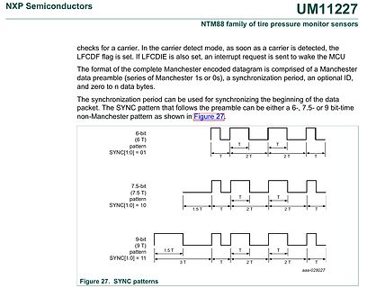
Datenblatt Ausschnitt zu Manchester SYNC Mustern
NXP Semiconductors UM11227 checks for a carrier. In the carrier detect mode, as soon as a carrier is detected, the LFCDF flag is set. If LFCDIE is also set, an interrupt request is sent to wake the MCU The format of the complete Manchester encoded datagram is comprised of a Manchester
-
Thread
Vorwiderstand für einphasig betriebenen Bewegungsmelder
und kann mir ggf einen Tip geben, welcher R da genügt? https://media.hornbach.de/hb/ownersmanual/as.46601856.PDF Im Datenblatt kann ich nichts zum Ruhestrom finden. Danke Euch Sven
S.3 weiterlesen Sven schrieb im Beitrag #7825408: > https://media.hornbach.de/hb/ownersmanual/as.46601856.PDF > > Im Datenblatt kann ich nichts zum Ruhestrom finden. Auf S.2 ist angegeben, dass bei einphasigem Anschluss (Fig.3 oberes Bild ) einer LED-Beleuchtung eine Mindestlast von 5W vorhanden
-
 Bild
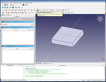
FreeCAD Benutzeroberfläche mit 3D-Modell und Python-Konsole
Elemente Filter Start Unbenannt 1 Python-Konsole >>> # del(ActiveSketch) >>> import PartDesignGui as app.getDocument('Unnamed').getObject('Sketch001') >>> # ActiveSketch.ViewObject.RestoreCamera() >>> # If ActiveSketch.ViewObject.tempVis.saveCamera() >>> # If ActiveSketch.ViewObject.ForceOrtho >>> #
-
 Bild
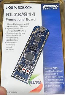
Verpackung einer Renesas RL78/G14 Promotional Board
RENESAS RL78/G14 Promotional Board Advanced features such as ADC operation without CPU wake up! High Performance core running at 1.27 DMIPS/MHz System cost reduction with on-chip Data flash & configurable high speed oscillator System safety functions to support
-
 Bild
Textausschnitt zu Synchronous Write-Write Collisions
contents of the memory location are unknown. Note that write-write collisions affect memory content, as opposed to write-read collisions which only affect data output.

-
Thread
Bauteile: PocketBeagle, smart aufgebaute LEDs, ESP32 mit STM32 uvam
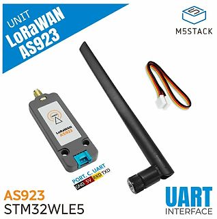
an.  Bildquelle: https://docs.m5stack.com/en/unit/Unit%20LoRaWAN-AS923 Nett ist am System vor Allem, dass es den LoRAWAN-Stack mitbringt und per UART AT-Kommandos entgegennimmt: [c] The module integrates the LoRaWAN protocol stack and supports three operating modes
greatly reduces the error in determining the propagation delay through the BSYNC transmission medium as compared to using a replica path. This feature makes the ADF4030 capable to time align the clock edges of BSYNC channels across multiple ADF4030 devices, independent of the tree or cascade architecture
-
 Bild
M5Stack LoRaWAN AS923 Modul mit Antenne
UNIT LoRaWAN AS923 M5STACK AS923 LoRaWAN AS923 PORT C UART GND 5V RXD TXD AS923 STM32WLE5 UART INTERFACE
-
 Bild
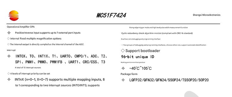
Datenblatt-Ausschnitt MC51F7424 von Shengsi Microelectronics
port inputs Internal fixed multiple magnification options The internal output is directly sampled as the internal channel of the ADC interrupt INTOX, TO, INT1X, T1, UART0, CMP0/1, ADC, T2, SPI, PWM1, PWM0, PWM1FB, UART1, CRC/CSS, T3 A total of 15 interrupt sources 4 levels of interrupt priority can
-
 Bild
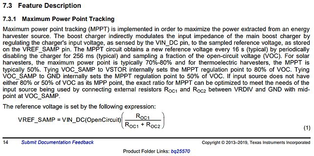
Datenblattabschnitt Maximum Power Point Tracking
modulates the input impedance of the main boost charger by regulating the charger's input voltage, as sensed by the VIN_DC pin, to the sampled reference voltage, as stored on the VREF_SAMP pin. The MPPT circuit obtains a new reference voltage every 16 s (typical) by periodically disabling the charger
-
 Bild
Dateimanager mit AVR-GCC Toolchain Dateien
Executable 921.4 KiB 05/04/2024 10:41 Desktop avr-ar Executable 949.2 KiB 05/04/2024 10:41 Trash Can avr-as Executable 1.2 MiB 05/04/2024 10:41 Applications avr-c++ Executable 2.2 MiB 05/04/2024 11:04 Linux-HDD avr-c++filt Executable 920.9 KiB 05/04/2024 10:41 Linux-SSD avr-cpp Executable 2.2 MiB 05/04/2024

-
Thread
[S] Datenblatt Intersil 80016 oder BBC Goertz-Metrawatt D 96x24/2000
specifications and do not have a data sheet. We were not allowed to retain any of the design information as part of the contractual agreement. 5V und 100mV anlegen und Anzeige beobachten. Wenn nötig, 7107 Datenblatt nehmen und auf der Basis den Schaltplan rauszeichnen. Viel wird gleich sein.
-
Thread
MPLAB X IDE AVR in ASM
AVRstudio4" in Assembler unterstützt. > Gruss Jan Hast vollkommen Recht. Das nutze ich bisher da AS6 ne Niete war und AS7 zum Anfang naja auch eher so lalal. Da MCP die AVRs erweitert hat bin ich der Meinung kann man sich doch auch mal evtl wenns passt im Hobby auch mal den ein oder anderen neueren
AS4.19 weiterhin beibehalten und das AS7 parallel verwenden
-
Thread
SDRAM mit Atmega328P
englischen Wikipedia-Artikel zu SDRAM steht Ähnliches: "Finally, if CKE is lowered at the same time as an auto-refresh command is sent to the SDRAM, the SDRAM enters self-refresh mode. This is like power down, but the SDRAM uses an on-chip timer to generate internal refresh cycles as necessary. The clock
-
 Bild
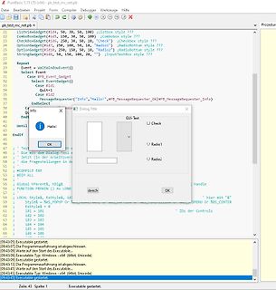
Code-Editor mit GUI-Programmierung und Programm-Ausgabe
Info Hallo! OK Radio1 Radio2 Check #COMPILE EXE #DIM ALL Global hParent&, hDlg& FUNCTION PBMAIN () As Long LOCAL Style&, ExStyle& id & Style& = %IS_POPUP Or %IS_WINDOW ExStyle = 0 id1 = 101 id2 = 102 id3 = 103 id4 = 104 id5 = 105 id6 = 106 #COMPILE EXE [09:43:09] Executable gestartet. [09:43:07] Die
-
Thread
[V] 20St. SILABS 8051 USB-EFM8UB20F64G-B - QFP32 (15€)
communication peripherals. https://www.mouser.de/ProductDetail/Silicon-Labs/EFM8UB20F64G-B-QFP32?qs=OycAS1CGnlj3PApaQXt1oA%3D%3D https://www.silabs.com/mcu/8-bit-microcontrollers/efm8-universal-bee/device.efm8ub20f64g-qfp32?tab=specs 15€ + 1€ Kompaktbrief (PS: Sind auch mehr da! Anfrage per PM)
-
Thread
Robuste Elektrolytkondensatoren, neue Mikrocontroller, Funkerei und Lesestoff
Vorstellung - dürfte das Erfüllen diverser EU-Direktiven sein: [c] New and upcoming regulations, such as the EU’s Batteries Regulation 2023/1542 introducing new sustainability and safety requirements for batteries, require the use of a Digital Product Passport (DPP) by 2027, including a digital record of
-
 Bild
Blockschaltbild eines Mikrocontrollers
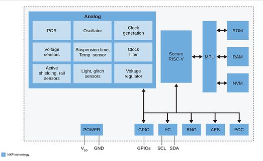
rail sensors Light, glitch sensors Voltage regulator Secure RISC-V MPU ROM RAM NVM POWER GPIO I2C RNG AES ECC VDD GND GPIOs SCL SDA NXP technology
-
Thread
Fairdevices - Open Hardware sucht Mitstreiter
Zitat von der Homepage: "The laundry machine is chosen as a first project item. Usually a small relay refuses its function or the main bearing starts rattling due to worn dampers. Within fairdevices, we would like to develop a universal circuit board that will
-
 Bild
Tabelle mit CMOS-Logikfamilien und Spezifikationen
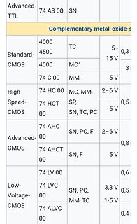
Advanced-TTL 74 AS 00 SN Complementary metal-oxide-s Standard-CMOS 4000 4500 TC 5-15 V 0,3 4000 MC1 3 74 C 00 MM 5 V High-Speed-CMOS 74 HC 00 MC, MM, 2-6 V 0,5 74 HCT 00 SP, SN, TC, PC 5 V 0,5 Advanced-CMOS 74 AHC 00 SN
-
Thread
AVR64DD32, UART-Ausgabe bleibt hängen, Assembler
folgende Funktion, die innerhalb einer ISR aufgerufen wird: [code] ; Send 8-bit unsigned number as two hex digits. ; Parameter: wri0. sendDbgHex: push wri0 swap wri0 andi wri0, 0x0F rcall sendDbgHexDigit pop wri0 push wri0 andi wri0, 0x0F rcall sendDbgHexDigit
Interrupt Controller All interrupt vectors are assigned to one of three possible priority levels, as shown in the table below. An interrupt request from a high-priority source will interrupt any ongoing interrupt handler from a normal-priority source. When returning from the high-priority interrupt
-
Thread
Timer mit NE555
Hier wäre noch eine Variante zur Regtriggerung vom NE555: https://www.hw2sw.com/2013/09/08/ne555-as-monostable-retriggerable/2/
-
Thread
Starke Verzerrung mit LM358-Verstärker bei 15 kHz
Übernahmeverzerrungen des LM324/358/321, allerdings mit 0.5V/us auch eine miese slew rate. The old LM741 looks as though it would be quite unusable, as its very limited 0.5 V/μs slew rate allows a full output swing only up to 4.4 kHz. Horrific as it may now appear, audio paths full of LM741s were quite common
potentially damaging current flow due to the input diode. Even if the GND > pin is also grounded, such as in single supply applications, there is a > possibility that the input ground will be negative relative to the op > amp’s internal ground node. Ground differences occur when there is poor > layout
-
 Bild
Einstellungsfenster für externe Tools in einer Software
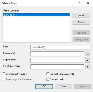
Command: ... Arguments: ... Initial directory: ... Use Output window Prompt for arguments Treat output as Unicode Close on exit OK Cancel Apply
-
Thread
[V] diverse Frequenzzähler
hab dir eine PN gesendet zu. Mi N. schrieb im Beitrag #7820572: > 2. unten links: > Pico-Fmeter-AS6501 Gruß bastler2022
Guten Nachmittag, ich hätte Interesse an dem Pico-Fmeter-AS6501. Wäre noch einer Verfügbar? Meine Mail: nick.holznagel@gmail.com Vielen Dank und viele Grüße, Nick Holznagel
-
Thread
SMD RF Stecker für 2-3 kW
und entspreched ein AlO PCB welches mit den Widerständen auf den KK geschraubt wird. Hier wird auch as Problem mit THT ersichtlich... Kay-Uwe R. schrieb im Beitrag #7821488: > Ich würde dort mal reinschauen: > https://www.fukowa.de/Dummyload_Blocks_overview.html > Für 1,5 GHz gibt es eine 1,7-kW-Version
-
Thread
Messung von Einzelevents mit 100ps zeitlicher Auflösung
brauche in einer Periode eher so 10-100 Ereignisse. Dann reichen ja 100 TDCs aus :-) Sieh Dir den AS6501 an, ob er für die gewünschte Pulsfrequenz schnell genug ist. Wenn nicht, rechne aus, wieviel Du von diesen Teilen brauchst. Der Rest ist Fleißarbeit.
deine Impulse im Abstand schneller als 10µs, funktioniert das natürlich nicht. Dann kannst du noch den AS über LVDS auslesen aber auch da brauchst du Zeit zum Auslesen, das Fifo ist begrenzt. Suchst du etwas käufliches, suche nach "Time Interval Analyzer".
-
Thread
avrdude.conf, wo finde ich die Argumente?
Laut Github sollte ja eigentlich "A script named avrdude-gui is installed into the same location as the AVRDUDE CLI program." sein.. Das konnte ich aber bei "avrdude-v8.0-windows-x64.zip" z.B. nicht finden.
Laut Github sollte ja eigentlich "A script named avrdude-gui is > installed into the same location as the AVRDUDE CLI program." sein.. So, ich habe den CI-Script etwas angepasst. Jetzt wird bei MinGW zumindest das GUI am Ende mit installiert. Probier mal: (CLang version) https://github.com
-
 Bild
Anwendungshinweis zu X1/X2 Kondensatorpositionen
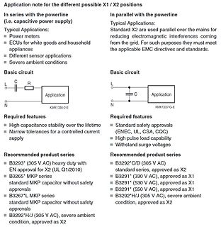
standard MKP capacitor without safety approvals B3292*H/J (305 V AC), severe ambient condition, approved as X2 Required features Standard safety approvals (ENEC, UL, CSA, CQC) High pulse load capability Without standsurge voltages Recommended product series B3292*C/D (305 V AC) standard series, approved as X2 B3291* (330 V AC), approved as X1 B3291* (530 V AC), approved as X1 B3291* (550 V AC), approved as X1 B3292*H/J (305 V AC), severe ambient condition, approved as X2
-
Thread
12V Laptop direkt am Zigarettenanzünder anschliessen?
2&biw=1265&bih=576&sxsrf=AHTn8zoz0fYMufNbEhURQTTrNXqkU7Ly3Q%3A1738408466281&ei=EgKeZ6fjEICtxc8P4_6dqAs&ved=0ahUKEwintO2YrKKLAxWAVvEDHWN_B7UQ4dUDCBI&uact=5&oq=akoya+ladeport+reparieren&gs_lp=EgNpbWciGWFrb3lhIGxhZGVwb3J0IHJlcGFyaWVyZW5I8EBQAFgAcAJ4AJABAJgBAKABAKoBALgBA8gBAJgCAKACAJgDAIgGAZIHAKAHAA&sclient





