-
Datei
TPS_UP.h
/*************************************************************************************** Titel: ATtiny TPS Unterprogramme Author: Christian Hottum File: TPS_UP.h Version: 0.1 Datum: 09.01.2015 Software: AVR-GCC 4.3.3 Target: ATtiny461A DESCRIPTION Variablen und Unterprogramme der TPS ***************
in „AVR TTiny 461 Pullup nicht aktiv?“ · Mikrocontroller und Digitale Elektronik ·
-
Datei
PWM.asm
****************************************************************** ;* Programm PWM.ASM ;* ;* Für ATtiny13 im Auslieferungszustand ( High = $FF ; Low = $6A ) ;* ;* ;* Der PWM-Pinn 5 ( OC0A ) soll die höchstmögliche Rechteckfrequenz liefern die der ;* ATtiny13 im Auslieferungszustand erzeugen kann ( Ca
in „ATtiny13 im Fast PWM-Mode 7 als Rechteckgenerator“ · Mikrocontroller und Digitale Elektronik ·
-
 Bild
Bild
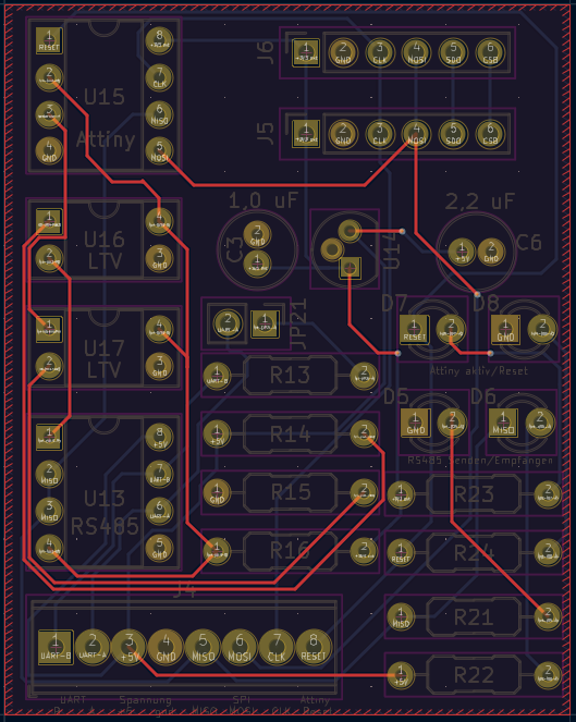
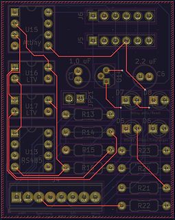
CAD-Ansicht eines Leiterplatten-Layouts
U15 Attiny, J6, 1 RISE, 2 GND, 3 CLK, 4 NO, 5 SDA, 6 SCL, J5, 1 TX, 2 GND, 3 CLK, 4 NO, 5 SDA, 6 SCL, 2,2 uF, C6, 1,0 uF, U16 LTV, U17 LTV, D7, D8, 1 RISE, 1 GND, JP21, R13, R14, D5, D6, 1 GND, 1 MISC, R15, R16, R23, R24, U13 RS485, 1 GND, 2 TX, 3 RX, 4 GND, R21, R22, 1 UART-B, 2 UART-A, 3 5V, 4 GND, 5 MOSI, 6 CLK, 7 RESET, 1 SPI, Attiny, UART, Spannung, MOSI, MISO, RX, TX
in „BME280 mit Attiny85 auslesen Daten per SN75176 an Pi senden“ · Mikrocontroller und Digitale Elektronik · · Layouts
-
Datei
irsnd-main-avr.c
additions from m.schoeldgen@hotmail.com * $Id: irsnd-main-avr.c,v 1.3 2016/09/09 08:01:11 fm Exp $ * * ATTINY2313 @ 8 MHz internal RC Osc with BODLEVEL 4.3V: lfuse: 0xE2 hfuse: 0xDC efuse: 0xF9 * * This program is free software; you can redistribute it and/or modify * it under the terms of the GNU General
in „IR Fernbedienung mit IRSND“ · Mikrocontroller und Digitale Elektronik ·
-
Datei
Slave.bas
Printbin #1 , Data_rx 'Waitms 500 '********************* Loop End I2c_start: Push R16 Push R20 Push R23 Push R24 Usisr = &B01001111 Bitwait Usisr.6 , Set 'Warte bis Start kondition fertig I2c_mode = 0 Sda_dir = 0 'SDA Input Usicr = &B11111000 'i2c Config Usisr = &B11110000 'Reset Flags pop R24 pop R23
in „Register in BASCOM“ · Mikrocontroller und Digitale Elektronik ·
-
 Bild
Bild
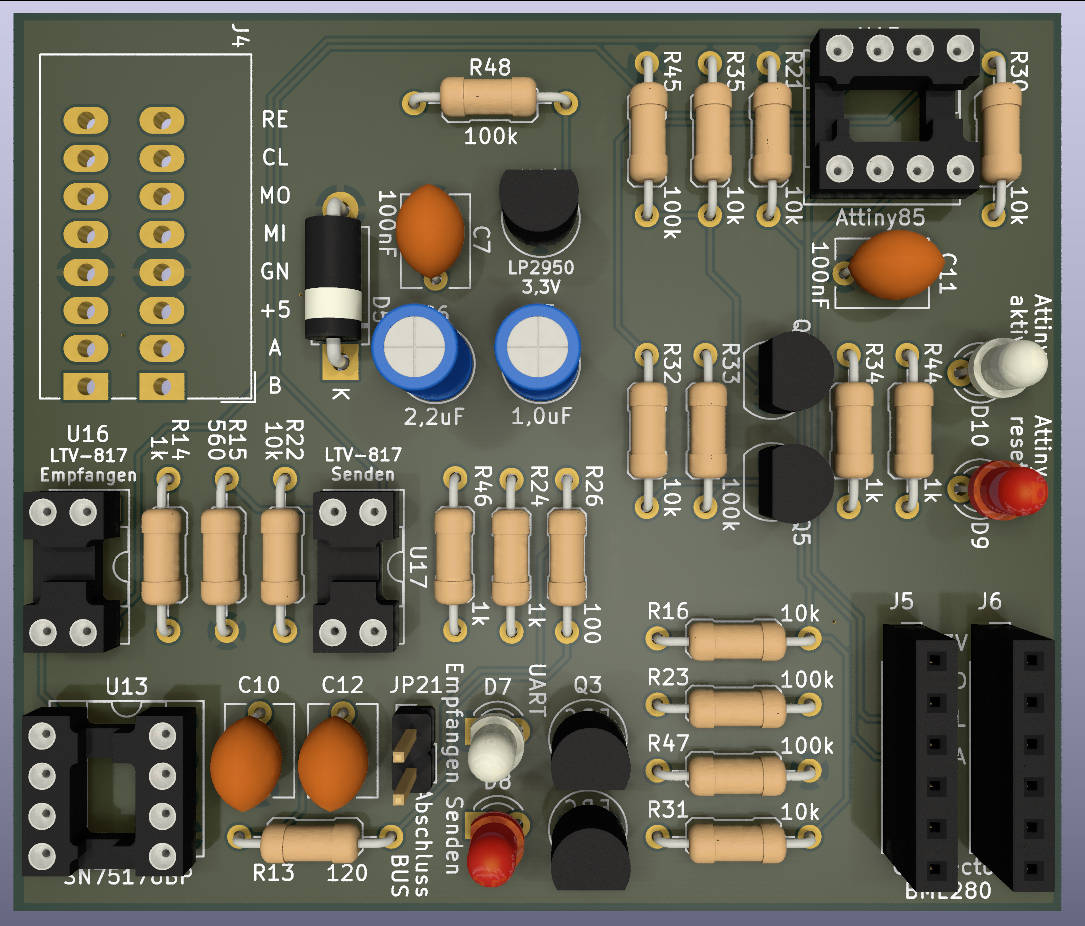
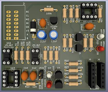
CAD-Ansicht eines Leiterplatten-Layouts
J4 R48 R45 R35 R21 R30 100k 10k 10k RE CL MO MI GN +5 A B K 100nF C7 LP2950 3,3V 100nF C11 Attiny85 Attiny akti D10 R34 R44 R33 R32 10k 10k 1k 1k 1k Q5 D9 R26 R24 R46 100 1k 1k LTV-817 Senden LTV-817 Empfangen U17 R15 560 R14 1k U16 R22 10k U13 C10 C12 JP21 Empfangen Senden Abschluss BUS UART R16 10k J5 J6 R23 100k R47 100k R31 10k R13 120
in „BME280 mit Attiny85 auslesen Daten per SN75176 an Pi senden“ · Mikrocontroller und Digitale Elektronik · · Layouts
-
Datei
RFM01-V8.asm
;RFM01-V8.asm ;Stand: 10.01.2010 ;Empfangsroutine für RFM01 ;Hardware: ATTiny2313 und RFM01 ;Autor Andreas Montnacher ;Fusebits: Takt 8 MHz intern, kein Taktvorteiler ;Assembler: GAVRASM, http://www.avr-asm-tutorial.net/avr_de/index.html .DEVICE ATTiny2313 .def ctrl=R1 ; Puffer
in „Beispielprogramm für RFM12 433MHz Funk-Module“ · Projekte & Code ·
-
Datei
diff-20100825.txt
freq_meter/cpu_mhz.h 2010-08-22 17:03:09.000000000 +0200 +++ freq_meter-20100825/cpu_mhz.h 2010-08-23 22:07:54.000000000 +0200 @@ -1,6 +1,6 @@ -// autogenerated by ./avr_isp.pl, Sun Aug 22 17:03:09 2010 +// autogenerated by ./avr_isp.pl, Mon Aug 23 22:07:54 2010 #ifndef CPU_MHZ -# define CPU_MHZ 12 -
in „Reziproker Frequenzzähler+ Optimierte 64bit uint Routinen“ · Projekte & Code ·
-
Datei
small_printf.c
minimalistischen (und im Funktionsumfang eingeschraenkten) Version von printf zur urspruenglichen Verwendung im ATtiny23 (sollte allerdings auch mit allen anderen AVR- Controllern funktionieren) 22.04.2016 R. Seelig Danke an www.mikrocontroller.net (Dr.Sommer, beric) Platzhalterfunktionen von tiny_printf ----------
in „#define Ich bekomme ein Makro nicht hin.“ · Mikrocontroller und Digitale Elektronik ·
-
Datei
intTest.lst
4.1 (C)2018 by DG4FAC ---------------------------------------------------------- Quelldatei: C:\ATtiny85 Lernpaket\Assembler-Files\intTest\intTest.asm Hexdatei: C:\ATtiny85 Lernpaket\Assembler-Files\intTest\intTest.hex Eepromdatei: C:\ATtiny85 Lernpaket\Assembler-Files\intTest\intTest.eep Kompiliert
in „attiny85 interrupt-behandlung“ · Mikrocontroller und Digitale Elektronik ·
-
Datei
DCF77_decoder_04Mai2026.asm
1 schieben rol r23 rol r23 andi r23, 0x03 ; relevante Bits filtern st z+, r23 ; Stunden Zehner speichern lds r23, dcftab+3 ; Byte 3 aus DCF77-Puffer0 holen ror r23 ; Bits 1-4 auf Bits 0-3 schieben andi r23, 0x0F ; relevante
-
Datei
DCF77_Decoder_020418.asm
1 schieben rol r23 rol r23 andi r23, 0x03 ; relevante Bits filtern st z+, r23 ; Stunden Zehner speichern lds r23, dcftab+3 ; Byte 3 aus DCF77-Puffer0 holen ror r23 ; Bits 1-4 auf Bits 0-3 schieben andi r23, 0x0F ; relevante
-
Datei
irmp_stm8.diff
irmp.c irmp/irmp.c --- irmp.orig/irmp.c 2015-09-21 14:46:25.126889000 +0200 +++ irmp/irmp.c 2015-10-25 23:18:11.000000000 +0100 @@ -2013,6 +2013,9 @@ ROM_GPIOPadConfigSet(IRMP_PORT_BASE, IRMP_PORT_PIN, GPIO_STRENGTH_2MA, GPIO_PIN_TYPE_STD_WPU); +#elif defined(__SDCC_stm8) + IRMP_GPIO_STRUCT->CR1 |= (1<<IRMP_BIT
-
Datei
Netzmessung_TWI.cpp
/* * Netzmessung_TWI.cpp * * Created: 14.08.2015 23:44:08 * Author: Ludwig * * TODO: * * */ #define F_CPU 8000000UL #define ICR_TOP 65535 #define I2C_ADRESS 2 //TWI initialisieren (Bei Adresse 2 Abfrage - Arduino Library - über 0x01 ??????????) #define
in „AVR Frequenzmessung, DS18S20“ · Mikrocontroller und Digitale Elektronik ·
-
PDF
BelleroPhon_Scaler_Rev05.pdf
CTRL_PWR4 R_GND SpicSpiceOrder 1 D5 G6K-2F-Y K8 VDD 1 8 CTRL_PWR5 Signal Output SpicSpiceOrder 1 D4 T2 22-23-2021 LOW - Mute aktiv OUT_L X2-1 G6K-2F-Y HIGH - Mute deaktiviert2311 K9 _MUTE_ L_GND X2-2 1 8 CTRL_PWR6 SpicSpiceOrder 1 0 1 D3 Dr K 1 Sc - 22-23-2021 e 2 OUT_R X3-1 K10 G6K-2F-Y Si 8 K 1 8 CTRL_PWR7
in „Verrückter R-2R Abschwächer (Audio)“ · Analoge Elektronik und Schaltungstechnik ·
-
PDF
DALI_readme_151001.pdf
integrierter DALI-Schnittstelle. Damit habe ich gearbeitet. Das Projekt besteht aus 2 Teilen: Der Hardware (ATTiny2313), programmiert in C und einem User-Interface, realisiert mit Python / TKinter. 1.) Hardware + C-Programm EinATTiny2313 fungiert als Gateway zwischen serieller Schnittstelle und dem DALI-Bus. Der
in „RS232-DALI-Gateway für ATtiny2313 / Python-GUI“ · Projekte & Code ·
-
Datei
Einschaltverzoegerung.asm
crystal ;* ;*************************************************************************** .device ATtiny2313 .include "tn2313def.inc" ;ATTiny2313 ;.include "2313def.inc" ;90S2313 .equ Bit0 =0 .equ Bit1 =1 .equ Bit2 =2 .equ Bit3 =3 .equ Bit4 =4 .equ Bit5 =5 .equ Bit6 =6 .equ Bit7 =7 .def temp =R18 .def Delay1 =r23 .def Delay2 =r24 .def Delay3 =r25 .def zeit =r26 .CSEG .ORG 0x00 ;rjmp reset ldi temp,RAMEND ;Initialize stackpointer out SPL,temp ;output Alle auf 11111111 ldi temp,0x00 out portd,temp ldi temp,0xff
in „Attiny 2313 Einschaltverhalten der Ports“ · Mikrocontroller und Digitale Elektronik ·
-
Datei
Temp.asm
clk/4= abt. 1kHz ;*************************************************************************** ; ATtiny26 Pin Assignment: ; 01 PB.0 MOSI/ CW-Tone-out ; 02 PB.1 MISO ; 03 PB.2 SCK ; 04 PB.3 OC1B MotDrive(U) ; 05 Vcc ; 06 Gnd ; 07 PB.4 AD7/RS232negVoltChgPump (T0) ; 08 PB.5 AD8 ; 09 PB.6 AD9/RS232 TxD-
in „Tiny26 Programm ändern in Programm für Mega8“ · Mikrocontroller und Digitale Elektronik ·
-
Datei
iotn841.h
DAMAGE. ****************************************************************************/ #ifndef _AVR_ATTINY841_H_INCLUDED #define _AVR_ATTINY841_H_INCLUDED #ifndef _AVR_IO_H_ # error "Include <avr/io.h> instead of this file." #endif #ifndef _AVR_IOXXX_H_ # define _AVR_IOXXX_H_ "iotn841.h" #else # error "
in „Neue ATtinies 441 und 841“ · Mikrocontroller und Digitale Elektronik ·
-
Datei
txlcd_i2c_demo.c
txlcd_i2c_demo.c Anbindung eines HS44780 kompatiblen Textdisplays ueber einen PCF8574 I2C I/O Expander MCU : ATtiny44 F_CPU : 8 MHz intern Fuses : fuer 8 MHz intern lo 0xe2 hi 0xdf Fuses : fuer ext. Quarz >= 8 MHz lo 0xde hi 0xdf Pinbelegung I2C --------------- PB0 = SDA PB1 = SCL 23.10.2018 R. Seelig ----------
in „(sehr) kleines "FrameWork" für ATtiny44“ · Projekte & Code ·
-
PDF
catalog.pdf
USD [QTY]: 9 [Category]: BJTs [Desc]: Bipolar Transistors - BJT SOT-23 NPN GP AMP Page 7/87 Bauteileliste vom 12.08.2022 MPN: FMMT617TA [ID]: 000088 [Price]: 0.27 USD [QTY]: 10 [Category]: BJTs [Desc]: Trans GP BJT NPN 15V 3A 625mW Automotive 3-Pin SOT-23 T/R MPN: FMMT618TA
-
PDF
catalog.pdf
]: 40 [Category]: BJTs [Desc]: Trans Gp Bjt NPN 20V 2.5A 625MW 3-PIN SOT-23 T/r / Trans NPN 20V 2.5A SOT23-3 MPN: BCX5616TA [ID]: 000093 [Price]: 0.11 USD [QTY]: 45 [Category]: BJTs [Desc]: Trans Gp Bjt NPN 80V 1A 2000MW 4-PIN(3+TAB) SOT-89 T/r / Trans NPN 80V 1A SOT-89 MPN:
-
Datei
tn2313def__2_.inc
Y ;* ;* Number :AVR000 ;* File Name :"tn2313def.inc" ;* Title :Register/Bit Definitions for the ATtiny2313 ;* Date :03.06.17 ;* Version :1.00 ;* Support E-mail :avr@atmel.com ;* Target MCU :ATtiny2313 ;* ;* DESCRIPTION ;* When including this file in the assembly program file, all I/O register ;* names
in „Welche .def ist die richtige?“ · Mikrocontroller und Digitale Elektronik ·
-
Datei
telefonadapter.c
/* Programm für ATtiny25 * h#s Henrik Haftmann, TU Chemnitz, 31. März 2009 - 8. Oktober 2015 * tabsize = 8, encoding = utf-8 (ohne Windows-Header BOM) */ #include <avr/io.h> #include <avr/pgmspace.h> #include <avr/interrupt.h
in „HEX-File passt nicht in Attiny 25“ · Mikrocontroller und Digitale Elektronik ·
-
 Bild
Bild
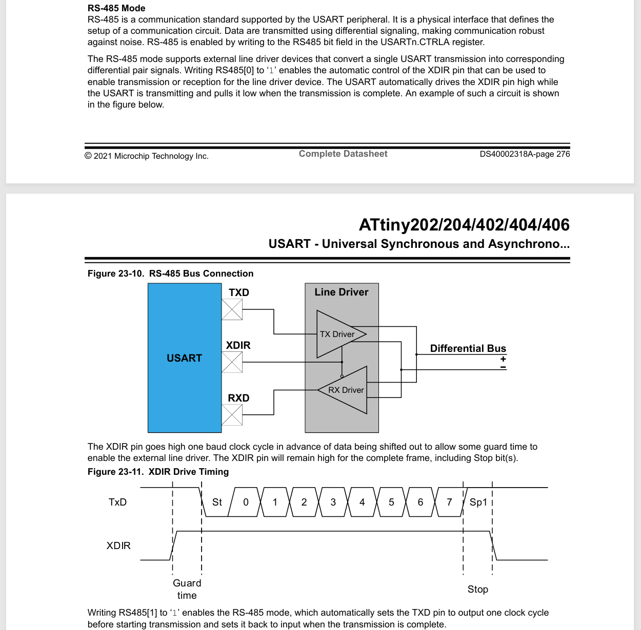
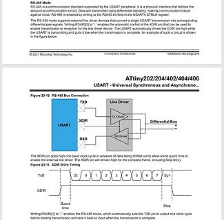
Datenblatt Ausschnitt ATtiny202 RS-485 Modus
RS-485 Mode ATtiny202/204/402/404/406 USART - Universal Synchronous and Asynchrono... Figure 23-10. RS-485 Bus Connection TXD Line Driver XDIR Differential Bus RXD RX Driver Figure 23-11. XDIR Drive Timing TxD St 0 1
in „BME280 mit Attiny85 auslesen Daten per SN75176 an Pi senden“ · Mikrocontroller und Digitale Elektronik · · Screenshots
-
Datei
dude5.4arduino_avr910.txt
0x1d = (unknown) Device code: 0x1e = (unknown) Device code: 0x1f = (unknown) Device code: 0x20 = ATtiny84 Device code: 0x21 = (unknown) Device code: 0x22 = (unknown) Device code: 0x23 = (unknown) Device code: 0x24 = (unknown) Device code: 0x25 = (unknown) Device code: 0x26 = (unknown) Device code: 0x27
in „avrdude - Probleme unter Mac OS X 10.7 (Lion)“ · Mikrocontroller und Digitale Elektronik ·
-
Datei
dude5.6_avr910.txt
0x1d = (unknown) Device code: 0x1e = (unknown) Device code: 0x1f = (unknown) Device code: 0x20 = ATtiny84 Device code: 0x21 = (unknown) Device code: 0x22 = (unknown) Device code: 0x23 = (unknown) Device code: 0x24 = (unknown) Device code: 0x25 = (unknown) Device code: 0x26 = (unknown) Device code: 0x27
in „avrdude - Probleme unter Mac OS X 10.7 (Lion)“ · Mikrocontroller und Digitale Elektronik ·
-
Datei
dude54arduino.txt
0x1d = (unknown) Device code: 0x1e = (unknown) Device code: 0x1f = (unknown) Device code: 0x20 = ATtiny84 Device code: 0x21 = (unknown) Device code: 0x22 = (unknown) Device code: 0x23 = (unknown) Device code: 0x24 = (unknown) Device code: 0x25 = (unknown) Device code: 0x26 = (unknown) Device code: 0x27
in „avrdude - Probleme unter Mac OS X 10.7 (Lion)“ · Mikrocontroller und Digitale Elektronik ·
-
Datei
ADWandler.txt
PB1 | ;| RESET an PB5 | ;| Referenzspannug VCC (5V) | ;| Masse GND (0V) | ;| | ;|Prozessor: | ;| ATTINY 13-20 DIP 3,6864 MHz | ;| | ;|Sprache: | ;| Assembler | ;| | ;|Datum: | ;| 16.04.2019 | ;| | ;|Version: | ;| 1.0 Ursprungsversion | ;| 2.0 neue Pinbelegung: | ;| Setting von PB5(AC0) -> PB2(AC1) |
in „AVR Attiny13 Assembler AD Wandler“ · Mikrocontroller und Digitale Elektronik ·
-
PDF
catalog-3.pdf
[QTY]: 40 [Category]: BJTs [Desc]: Trans Gp Bjt NPN 20V 2.5A 625MW 3-PIN SOT-23 T/r / Trans NPN 20V 2.5A SOT23-3 MPN: BCX5616TA [ID]: 000093 [Price]: 0.1516 USD [QTY]: 45 [Category]: BJTs [Desc]: Trans Gp Bjt NPN 80V 1A 2000MW 4-PIN(3+TAB) SOT-89 T/r / Trans NPN 80V 1A SOT-89 MPN
-
PDF
AVR4100.pdf
MegaAVR ATmega88P X32K_1v8_ULP MegaAVR ATmega88PA X32K_1v8_ULP MegaAVR ATmega8A X32K_2v7 TinyAVR ATtiny2313A X32K_1v8 TinyAVR ATtiny24 X32K_1v8 TinyAVR ATtiny24A X32K_1v8 TinyAVR ATtiny25 X32K_1v8 TinyAVR ATtiny261 X32K_1v8 TinyAVR ATtiny261A X32K_1v8 TinyAVR ATtiny4313 X32K_1v8 TinyAVR ATtiny44 X32K_1v8 TinyAVR ATtiny44A X32K_1v8 TinyAVR ATtiny45 X32K_1v8 TinyAVR ATtiny461 X32K_1v8 TinyAVR ATtiny461A X32K_1v8 TinyAVR ATtiny84 X32K_1v8 TinyAVR ATtiny861A X32K_1v8 XMEGA ATxmega128A1 X32K_XMEGA XMEGA ATxmega128A3 X32K_XMEGA
in „Passende Kondensatoren für Uhrenquarz gesucht“ · Mikrocontroller und Digitale Elektronik ·
-
Datei
avrdude_crash.txt
00000000 00:00 0 7f6040bca000-7f6040cd2000 r-xp 00000000 08:01 2626116 /lib/x86_64-linux-gnu/libm-2.23.so 7f6040cd2000-7f6040ed1000 ---p 00108000 08:01 2626116 /lib/x86_64-linux-gnu/libm-2.23.so 7f6040ed1000-7f6040ed2000 r--p 00107000 08:01 2626116 /lib/x86_64-linux-gnu/libm-2.23.so 7f6040ed2000-7f6040ed3000 rw-p 00108000 08:01 2626116 /lib/x86_64-linux-gnu/libm-2.23.so 7f6040ed3000-7f6040eeb000 r-xp 00000000 08:01 2626192 /lib/x86_64-linux-gnu/libpthread-2.23.so 7f6040eeb000-7f60410ea000 ---p 00018000 08:01 2626192 /lib/x86_64-linux-gnu/libpthread-2.23.so 7f60410ea000
in „Avrdude stürzt ab, beim Flash/EEPROM Lesen über usbtiny, Ubuntu 16.04“ · PC Hard- und Software ·
-
 Bild
Bild
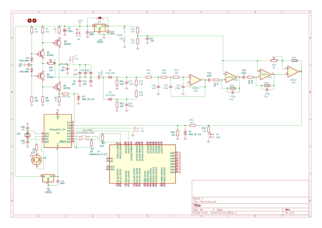
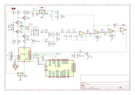
Schaltplan mit Raspberry Pi und Verstärkerschaltung
+12V, J3, D7, R13, C14, U4, TL09, R17, R18, C21, C23, LM324, U3, R27, R2, R19, R24, C22, C24, R25, R22, R20, R26, R10, R9, R7, R5, R4, R1, R16, R15, R14, R11, R8, R6, R3, C10, C5, C7, C8, C12, C15, C16, C19, C20, C21, C22, C23, C24, Q1, Q2, Q3, D1, D2, D4, D5, D6, U2, ATtiny164-55, P3, P4, P1, P0, RESET/PA0, Raspberry_Pi_2_3, 3v3, 5v, GPIO0 bis GPIO13, J4, L78L33, IN, OUT, GND
in „Bitte nicht nachmachen: PE des DSO abkleben?“ · Analoge Elektronik und Schaltungstechnik · · Schaltpläne
-
Datei
DCF_Filter_Tiny_02.bas
"m162def.dat" '_Chip = 28 '$regfile = "m328pdef.dat" '_Chip = 60 '$regfile = "m32def.dat" '_Chip = 23 '$regfile = "m16def.dat" '_Chip = 18 '$regfile = "m8def.dat" '_Chip = 17 $regfile = "attiny13a.dat" '$regfile = "attiny13.dat" ' *** Mit Quarz, Frequenz '$crystal = 16000000 '$crystal = 12800000 '$crystal
in „DCF77 Auswertung (ein bisschen anders)“ · Mikrocontroller und Digitale Elektronik ·
-
PDF
Inkontinenzsensor_Beschreibung.pdf
Matratzenschoner „Matress Protector“ von blumtal (Blumtal 2er Set Wasserdichter Matratzenschoner 90 x 200: 23,99€ bei Amazon). Der eigentliche Sensor besteht aus nachträglich aufgebrachten 2 Leitern (0,5 mm Kupfer-Silberdraht), deren Leiter- und Isolationswiderstand laufend gemessen wird. • Automatische Erkennung
-
Datei
dude511.txt
unknown) avrdude: Recv: . [1f] Device code: 0x1f = (unknown) avrdude: Recv: [20] Device code: 0x20 = ATtiny84 avrdude: Recv: ! [21] Device code: 0x21 = (unknown) avrdude: Recv: " [22] Device code: 0x22 = (unknown) avrdude: Recv: # [23] Device code: 0x23 = (unknown) avrdude: Recv: $ [24] Device code: 0x24
in „avrdude - Probleme unter Mac OS X 10.7 (Lion)“ · Mikrocontroller und Digitale Elektronik ·
-
Datei
dude511_mit_arduino_conf.txt
unknown) avrdude: Recv: . [1f] Device code: 0x1f = (unknown) avrdude: Recv: [20] Device code: 0x20 = ATtiny84 avrdude: Recv: ! [21] Device code: 0x21 = (unknown) avrdude: Recv: " [22] Device code: 0x22 = (unknown) avrdude: Recv: # [23] Device code: 0x23 = (unknown) avrdude: Recv: $ [24] Device code: 0x24
in „avrdude - Probleme unter Mac OS X 10.7 (Lion)“ · Mikrocontroller und Digitale Elektronik ·
-
Datei
avr910.asm
for ;* different polling Codes. Skip 0xFF Byte polling. (was buggy for some Controllers) ;* Added ATTiny2313 (device Code 0x23), and ATMega8535 (0x6A)Support. ;* Not Supported from avrprog, avrdude Support possible. ;* Reorganised Table for Page Mode Chips with Pagesize. Adding different Pagesizes ;*
-
PDF
Inkontinenzsensor_Beschreibung.pdf
Matratzenschoner „Matress Protector“ von blumtal (Blumtal 2er Set Wasserdichter Matratzenschoner 90 x 200: 23,99€ bei Amazon). Der eigentliche Sensor besteht aus nachträglich aufgebrachten 2 Leitern (0,5 mm Kupfer-Silberdraht), deren Leiter- und Isolationswiderstand laufend gemessen wird. • Automatische Erkennung
-
Datei
display.asm
************************************************************ .include "tn2313def.inc" ;Prozessor ATTINY2313 ; ATtiny2313 Display TC1602A 4 bit Mode ; +--+-+--+ 2 Zeilen zu je 16 Stellen ; !RESET | |_| | VCC Memoryadr.: Zeile1: 00 und Zeile2: 40h ; (RX)PD0 | | PB7(SCK) n.c. ; (TX)PD1 | | PB6(MISO) n.c
in „LCD Routine Funktioniert nicht“ · Mikrocontroller und Digitale Elektronik ·
-
Datei
I2Cslave_ATtiny13_Elektor.BAS
'get 1st byte I2c_10: 'wait for SCL=0 sbic pinb,scl rjmp i2c_10 ldi r22,8 'bits to receive=8 lds r23,{address} 'I2C address->R23 I2c_11: sbis pinb,scl 'wait for SCL=1 rjmp i2c_11 sbic pinb,sda rjmp i2c_13 I2c_12: 'if SDA=0 sbic pinb,sda rjmp i2c_wait_for_start ' SDA 0->1? I2CSTOP! (unexpected: wait
in „ATTINY13 I2C to Uart converter“ · Mikrocontroller und Digitale Elektronik ·
-
Datei
Strom_25A.bas
20) , 15 Readeeprom Dataregister(21) , 16 Readeeprom Dataregister(22) , 17 Readeeprom Dataregister(23) , 18 Readeeprom Dataregister(24) , 19 Readeeprom Dataregister(25) , 20 Readeeprom Dataregister(26) , 21 Readeeprom Dataregister(27) , 22 Readeeprom Dataregister(28) , 23 Readeeprom Dataregister(29)
in „Fehler in Bascom?“ · Mikrocontroller und Digitale Elektronik ·
-
Datei
main.c
/* * attiny841_spi.c * * Created: 04.10.2015 11:02:38 * Author : sschultewolter */ #ifndef F_CPU #error Define F_CPU #endif #include <avr/io.h> #include <util/delay.h> #include "mcp.h" int main(void) { spi_init
in „Problem MCP23S17 und avr-gcc“ · Mikrocontroller und Digitale Elektronik ·
-
Datei
VirtualWire.cpp
defined #endif #include "VirtualWire.h" #include <util/crc16.h> #undef TIMER_VECTOR #ifdef __AVR_ATtiny85__ # define TIMER_VECTOR TIM0_COMPA_vect #elif defined(__AVR_ATtiny84__) || defined(__AVR_ATtiny24__) || defined(__AVR_ATtiny44__) // Why can't Atmel make consistent? # define TIMER_VECTOR TIM1_COMPA_vect
in „Korrigierte "VirtualWire" Library für Attiny84 / 85“ · Projekte & Code ·
-
Datei
IR8_V12_SAA3008.asm
/* Alternativ-Firmware für IR8-Bausatz Version 1.2 von Pollin Der ATTiny2313 sollte im Originalzustand gefust sein, also mit aktiviertem internen 8MHz-RC-Oszillator. Achtung: Der zum Bausatz gehörende ATTiny2313 ist auf 4MHz gefust. Der Zustand der CKDIV8-Fuse ist egal,
in „Quellcode für den Pollin Fernsteuer Bausatz“ · Mikrocontroller und Digitale Elektronik ·
-
Datei
avr910.asm
for ;* different polling Codes. Skip 0xFF Byte polling. (was buggy for some Controllers) ;* Added ATTiny2313 (device Code 0x23), and ATMega8535 (0x6A)Support. ;* Not Supported from avrprog, avrdude Support possible. ;* Reorganised Table for Page Mode Chips with Pagesize. Adding different Pagesizes ;*
-
Datei
tn85def.inc
" ;* Title : Register/Bit Definitions for the ATtiny85 ;* Date : 2007-02-28 ;* Version : 2.24 ;* Support E-mail : avr@atmel.com ;* Target MCU : ATtiny85 ;* ;* DESCRIPTION ;* When including this file in the assembly program file, all I/O register ;* names
in „Peter Danneggers Bootloader (fastboot) für AVR-GCC-Toolchain“ · Projekte & Code ·
-
Datei
definition_tn2313.txt
" ;* Title : Register/Bit Definitions for the ATtiny2313 ;* Date : 2005-01-11 ;* Version : 2.14 ;* Support E-mail : avr@atmel.com ;* Target MCU : ATtiny2313 ;* ;* DESCRIPTION ;* When including this file in the assembly program file, all I/O register
in „Attiny2313 programmieren“ · Mikrocontroller und Digitale Elektronik ·
-
Datei
tn85def.inc
" ;* Title : Register/Bit Definitions for the ATtiny85 ;* Date : 2009-12-11 ;* Version : 2.35 ;* Support E-mail : avr@atmel.com ;* Target MCU : ATtiny85 ;* ;* DESCRIPTION ;* When including this file in the assembly program file, all I/O register ;* names
in „LCD über nur einen IO-Pin ansteuern“ · Projekte & Code ·
-
Datei
tn2313def.inc
" ;* Title : Register/Bit Definitions for the ATtiny2313 ;* Date : 2010-08-20 ;* Version : 2.35 ;* Support E-mail : avr@atmel.com ;* Target MCU : ATtiny2313 ;* ;* DESCRIPTION ;* When including this file in the assembly program file, all I/O register
in „Welche .def ist die richtige?“ · Mikrocontroller und Digitale Elektronik ·