-
Datei
AVR910JS_2313_v3_3_STK500.asm
from table mov pgm_mode,r0 ;Copy to pgm_mode adiw ZL,1 ;Increment pointer ret ;Programmer ID ID: .db "AVR ISP",0 ;Device codes and program mode table (0(zero)=byte mode, <>0=page mode) ;i.e. 'P' can be used for page mode for easier reading. device_codes: ; [jw] Commented out all but one device code.
in „STK500 spinnt“ · Mikrocontroller und Digitale Elektronik ·
-
PDF
Eng_ET-TFT240320TP-3.2.pdf
10 DB3-H 1 20 DB2 11 DBD1 DB4-H 11 12 DB5-H 19 T/R VCC DB3 12 DBD2 13 14 OE 100n DBD3 DB6-H 15 16 DB7-H DB4 13 DBD4 DB8-H 17 18 DB9-H DB8-H 2 A0 B0 18 DB8 DB5 14 DBD5 DB10-H 19 20 DB11-H DB9-H 3 A1 B1 17 DB9 DB6 15 DBD6 C DB12-H 21 22 DB13-H DB10-H 4 A2 B2 16 DB10 DB7 16 DBD7 C DB14-H 23 24 DB15-H DB11-H 5 A3 B3 15 DB11 DB8 17 DBD8 Y- X- DB12-H 6 14 DB12 DB9 18 Y+ 25 26 X+ DB13-H 7 A4 B4 13 DB13 DB10 19 DBD9
in „LCD 240x320 color + touch screen module“ · Mikrocontroller und Digitale Elektronik ·
-
Datei
lcdcon_ft245_4bit.asm
231 , 231 , 60 , 90 , 153 .db 128 , 224 , 248 , 254 , 248 , 224 , 128 , 0 .db 2 , 14 , 62 , 254 , 62 , 14 , 2 , 0 .db 24 , 60 , 126 , 24 , 24 , 126 , 60 , 24 .db 102 , 102 , 102 , 102 , 102 , 0 , 102 , 0 .db 127 , 219 , 219 , 123
in „LCD Controller für 640x480 LCD mit mega8515“ · Projekte & Code ·
-
Datei
8080int-jmp.asm
... .equ ZFL_S = 7 .equ ZFL_Z = 6 .equ ZFL_H = 4 .equ ZFL_P = 2 .equ ZFL_N = 1 .equ ZFL_C = 0 .equ AVR_T = SREG_T .equ AVR_H = SREG_H .equ AVR_S = SREG_S .equ AVR_V = SREG_V .equ AVR_N = SREG_N .equ AVR_Z = SREG_Z .equ AVR_C = SREG_C ;------------------------------------------------; ; Load table value
in „CP/M auf ATmega88“ · Mikrocontroller und Digitale Elektronik ·
-
Datei
ALgAn102.bas
, $00 ' 3 .db $00 , $18 , $14 , $7e , $10 , $00 ' 4 .db $00 , $2e , $4a , $4a , $32 , $00 ' 5 .db $00 , $3c , $4a , $4a , $30 , $00 ' 6 .db $00 , $02 , $72 , $0a , $06 , $00 ' 7 .db $00 , $34 , $4a , $4a , $34 , $00 ' 8 .db $00 , $0c , $52 , $52 , $3c , $00 ' 9 .db $00 , $04 , $7e , $00 , $60 , $18 ' : [1/] .db $06 , $00 , $64 , $52 , $52 , $4c ' ; [/2] .db $06 , $00 , $18 , $14 , $7e , $10 ' < [/4] .db $00 , $14 , $14
in „Bascom .def not found“ · Mikrocontroller und Digitale Elektronik ·
-
Datei
lcd.S.txt
vom Arduino D-Pin 8 dauerhaft auf GND verbinden und spart sich einen I/O-Pin vom Arduino ein ! // DB7 - Arduino D-Pin 2 / Atmel PD2 // DB6 - Arduino D-Pin 3 / Atmel PD3 // DB5 - Arduino D-Pin 4 / Atmel PD4 // DB4 - Arduino D-Pin 5 / Atmel PD5 // Wartezeiten für Wartefunktionen: // shortwait: r16 x 3
in „LCD-Display funktioniert nur nach Übertragung des Programms“ · Mikrocontroller und Digitale Elektronik ·
-
Datei
lcd.S.txt
vom Arduino D-Pin 8 dauerhaft auf GND verbinden und spart sich einen I/O-Pin vom Arduino ein ! // DB7 - Arduino D-Pin 2 / Atmel PD2 // DB6 - Arduino D-Pin 3 / Atmel PD3 // DB5 - Arduino D-Pin 4 / Atmel PD4 // DB4 - Arduino D-Pin 5 / Atmel PD5 // Wartezeiten für Wartefunktionen: // shortwait: r16 x 3
in „LCD-Display funktioniert nur nach Übertragung des Programms“ · Mikrocontroller und Digitale Elektronik ·
-
Datei
8080int-jmp.asm
... .equ ZFL_S = 7 .equ ZFL_Z = 6 .equ ZFL_H = 4 .equ ZFL_P = 2 .equ ZFL_N = 1 .equ ZFL_C = 0 .equ AVR_T = SREG_T .equ AVR_H = SREG_H .equ AVR_S = SREG_S .equ AVR_V = SREG_V .equ AVR_N = SREG_N .equ AVR_Z = SREG_Z .equ AVR_C = SREG_C ;------------------------------------------------; ; Load table value
in „CP/M auf ATmega88“ · Mikrocontroller und Digitale Elektronik ·
-
Datei
8080int-jmp.asm
... .equ ZFL_S = 7 .equ ZFL_Z = 6 .equ ZFL_H = 4 .equ ZFL_P = 2 .equ ZFL_N = 1 .equ ZFL_C = 0 .equ AVR_T = SREG_T .equ AVR_H = SREG_H .equ AVR_S = SREG_S .equ AVR_V = SREG_V .equ AVR_N = SREG_N .equ AVR_Z = SREG_Z .equ AVR_C = SREG_C ;------------------------------------------------; ; Load table value
in „CP/M auf ATmega88“ · Mikrocontroller und Digitale Elektronik ·
-
Datei
bios6V127.asm
; dcr c ; jnz rdsek_l ; dcr b ; jnz rdsek_l ; shld datadr ; Bufferadresse sichern ret ; ; ; msg1: db 0ah db 0dh db "T" db "h" db "i" db "s" db 20h db "i" db "s" db 20h db "6" ; 60 K db "0" db 20h db "K" db 20h db "C" db "P" db "/" db "M" db 20h db "R" db "e" db "l" db "." db 20h db "2" db "." db "2"
in „Suche MOPPEL Projekt in Heft oder .PDF“ · Mikrocontroller und Digitale Elektronik ·
-
Datei
lcdcon_ft245_4bit320.asm
231 , 231 , 60 , 90 , 153 .db 128 , 224 , 248 , 254 , 248 , 224 , 128 , 0 .db 2 , 14 , 62 , 254 , 62 , 14 , 2 , 0 .db 24 , 60 , 126 , 24 , 24 , 126 , 60 , 24 .db 102 , 102 , 102 , 102 , 102 , 0 , 102 , 0 .db 127 , 219 , 219 , 123
in „LCD Controller für 640x480 LCD mit mega8515“ · Projekte & Code ·
-
Datei
lcdcon_ft245_4bit320.asm
231 , 231 , 60 , 90 , 153 .db 128 , 224 , 248 , 254 , 248 , 224 , 128 , 0 .db 2 , 14 , 62 , 254 , 62 , 14 , 2 , 0 .db 24 , 60 , 126 , 24 , 24 , 126 , 60 , 24 .db 102 , 102 , 102 , 102 , 102 , 0 , 102 , 0 .db 127 , 219 , 219 , 123
in „LCD Controller für 640x480 LCD mit mega8515“ · Projekte & Code ·
-
Datei
main.asm
: .db "Address: ", 0 szData: .db " Data: ", 0 szLdcs: .db "LDCS returned: ", 0 szLds: .db "LDS returned: ", 0, 0 szConfirm: .db " Confirm (y/n): ", 0, 0 szEnteringCEK: .db "Entering Chip Erase key...", '\r
in „AVR64DD28, mEDBG, Studio 7.0 - Fehler beim Schreiben von Fuses“ · Mikrocontroller und Digitale Elektronik ·
-
Datei
hsb2rgb.asm
;HSB nach RGB Umrechnung (für LEDS) rein in AVR-Assembler, ziemlich simpel ;Der Code ist hier zwar für AVR geschrieben, ist aber derart simpel, dass er auf jeden Controller ;ohne grossen Aufwand portiert werden kann. Es bedarf keinerlei Spezialbefehle
in „Fertig: HSB->RGB Umrechnung rein in Assembler, auch für ATiny“ · Projekte & Code ·
-
Datei
take4.lst
zero_reg__ = 1 8 .global __do_copy_data 9 .global __do_clear_bss 10 .stabs "/home/sunshine/elektronik/avr-tests/mpadd/",100,0,2,.Ltext0 11 .stabs "take4.c",100,0,2,.Ltext0 12 .text 13 .Ltext0: 14 .stabs "gcc2_compiled.",60,0,0,0 15 .stabs "int:t(0,1)=r(0,1);-32768;32767;",128,0,1,0 16 .stabs "char:t(0,2
in „Byteweise mit Carry addieren?“ · Mikrocontroller und Digitale Elektronik ·
-
Datei
CFD_blinken.asm
; SLdt 201020 ; Clock Failure Detection ; Antippen von J215 auf 'AVR128DB48 Curiosity Nano' .include "AVR128DB48def.inc" .def tmp0 = r16 .macro CCP ldi tmp0,CPU_CCP_IOREG_gc sts CPU_CCP,tmp0 .endmacro rjmp reset .org CLKCTRL_CFD_vect sbi VPORTB_IN,3 rcall blinken ; langsamer
in „AVR128DB - Clock Failure Detection“ · Mikrocontroller und Digitale Elektronik ·
-
Datei
vergleich.txt
BASCOM AVR: ============================================= $regfile = "at26def.dat" $crystal = 1000000 Dim K As Byte Config Lcdbus = 4 Config Lcd = 20 * 2 Config Lcdpin = Pin , Db4 = Pa.3 , Db5 = Pa.2 , Db6 = Pa.1 , Db7 = Pa.0 , E = Pa.4 , Rs = Pa.5 Cursor Off Cls Do Locate 1 , 7 K = 8 Lcd K Loop End ============================================ Report : TST Date : 06-11-2003 Time : 19:13:26 Compiler : BASCOM-AVR LIBRARY
in „Vergleich BASOM-CODEVISION“ · Mikrocontroller und Digitale Elektronik ·
-
Datei
Funktionsdec_mit_CV28_09_01_2009.asm
Frei und CV10 Frei .db 0xFF, 0xFF ; CV11 Frei und CV12 Frei .db 0xFF, 0xFF ; CV13 Frei und CV14 Frei .db 0xFF, 0xFF ; CV15 Frei und CV16 Frei .db 0xC8, 0x8A ; CV17 HI-Byte und CV18 LO-Byte .db 0x00, 0xFF ; CV19 Consist und CV20 Frei .db 0xFF, 0xFF ; CV21 Frei und CV22 Frei .db 0xFF, 0xFF ; CV23 Frei und CV24 Frei .db 0xFF, 0xFF ; CV25 Frei und CV26 Frei .db 0x00, 0x02 ; CV27 Frei und CV28 Funktionauswahl .db 0x00, 0xFF ; CV29 Configuration
in „DCC Decoder“ · Projekte & Code ·
-
Datei
Funktionsdec_mit_CV28_09_01_2009.txt
Frei und CV10 Frei .db 0xFF, 0xFF ; CV11 Frei und CV12 Frei .db 0xFF, 0xFF ; CV13 Frei und CV14 Frei .db 0xFF, 0xFF ; CV15 Frei und CV16 Frei .db 0xC8, 0x8A ; CV17 HI-Byte und CV18 LO-Byte .db 0x00, 0xFF ; CV19 Consist und CV20 Frei .db 0xFF, 0xFF ; CV21 Frei und CV22 Frei .db 0xFF, 0xFF ; CV23 Frei und CV24 Frei .db 0xFF, 0xFF ; CV25 Frei und CV26 Frei .db 0x00, 0x02 ; CV27 Frei und CV28 Funktionauswahl .db 0x00, 0xFF ; CV29 Configuration
in „DCC Decoder“ · Projekte & Code ·
-
Datei
fcntl.lst
31 .stabs "complex long double:t(0,18)=r(0,18);8;0;",128,0,0,0 32 .stabs "__builtin_va_list:t(0,19)=*(0,20)=(0,20)",128,0,0,0 33 .stabs "_Bool:t(0,21)=@s8;-16;",128,0,0,0 34 .stabs "C:/PROGRA~1/AVRGCC/avr/include/string.h",130,0,0,0 35 .stabs "C:/PROGRA~1
in „Compiler-Fehler?“ · Mikrocontroller und Digitale Elektronik ·
-
Datei
8515FZM1.asm
.db 0b00000000,0b00001000,0b00000000,0b00000000 ;4 .db 0b00000000,0b00010000,0b00000000,0b00000000 ;5 .db 0b00000000,0b00100000,0b00000000,0b00000000 ;6 .db 0b00000000,0b01000000,0b00000000,0b00000000 ;7 .db 0b00000000,0b10000000,0b00000000,0b00000000 ;8 .db 0b00000000,0b00000000,0b00000000,0b00000010 ;9 .db 0b00000000,0b00000000,0b00000000,0b00000100 ;10 .db 0b00000000,0b00000000,0b00000000,0b00001000 ;
in „Timer1: Compare-mode spinnt“ · Mikrocontroller und Digitale Elektronik ·
-
Datei
foo.dwarf-3.txt
LASF937 .byte 0x4 .file 12 "e:\\winavr\\4.8_2013-03-06\\avr\\include\\avr\\io.h" .byte 0x3 .uleb128 0x7 .uleb128 0xc .byte 0x5 .uleb128 0x61 .long .LASF938 .file 13 "e:\\winavr\\4.8_2013-03-06\\avr\\include\\avr\\sfr_defs.h" .byte 0x3 .uleb128 0x63 .uleb128
in „Simple C Frage zum Typ enum“ · Mikrocontroller und Digitale Elektronik ·
-
Datei
Temp.asm
data shift reg+buf .DB -1 ;R22:Rtxreg:RS232 tx data shift reg+buf .DB 0 ;R23:Ramuxctr:AMUX index ctr .DB -1 ;R24: .DB -1 ;R25: .DB -1 ;R26 .DB -1 ;R27 .DB -1 ;R28: RrpmL rpm ctr .DB -1 ;R29: RrpmH .DB 30 ;R30 .DB 0 ;R31 ;
in „Tiny26 Programm ändern in Programm für Mega8“ · Mikrocontroller und Digitale Elektronik ·
-
Datei
main.cpp
PLL_fuer_Landolt.cpp * * DDS Code von S.Landolt * * Created: 12.03.2021 * Author : Devil-Elec * Code angepasst für AVR128DB48 mit TCD0 und PLL * Board: AVR128DB48 Curiosity Nano * * Ausgangspin: PA5 */ // #define TIMERTAKT_PLL // für 48MHz PLL Takt "einkommentieren" #include <avr/io.h> #include <avr/pgmspace.h> void
in „Attiny2313 Timer16 Bit, Normal Mode, unsauber“ · Mikrocontroller und Digitale Elektronik ·
-
Datei
main.c
#include <avr/io.h> #include <avr/interrupt.h> #include <avr/sleep.h> #include <stdlib.h> #include <util/delay.h> #include "rf12.h" const uint8_t bel = 7; // Start Byte [0] const uint8_t dev_id_1 = 1; // Device ID
in „atmega88p ADC sleep Problem“ · Mikrocontroller und Digitale Elektronik ·
-
 Bild
Bild
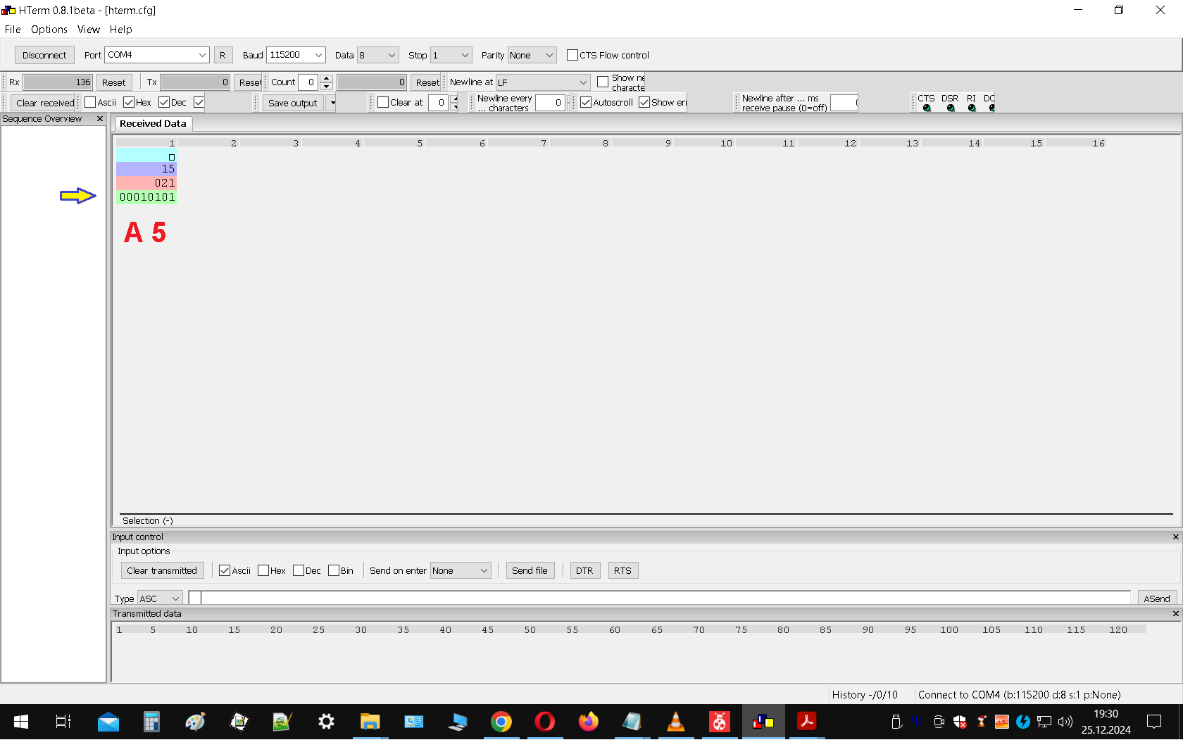
HTerm Terminal Software Screenshot
HTerm 0.8.beta - [Hterm.cfg] File Options View Help Port COM4 Baud 115200 Data 8 Stop 1 Parity None CTS Flow control Rx 136 Reset Count 0 Reset Newline at LF Show rx Clear received Ascii Hex Dec Clear at 0 Newline every characters 0 Autoscoll Show en Sequence Overview Received Data 1 2 3 4 5 6 7 8 9 10 11 12 13 14 15 16 15 021 00010101 A 5 Selection (-) Input control Clear transmitted Ascii Hex Dec Send on enter None Send file DTR RTS Type ASC Transmitted data 1 5 10 15 20 25 30 35 40 45 50 55 60 65 70 75 80 85 90 95 100 105 110 115 120 History -/0/10 Connect to COM4 (b:115200 d8 s:1 p:None 19
in „AVR128DA64 TCA1 funktioniert nicht mit alternativen Output?“ · Mikrocontroller und Digitale Elektronik · · Screenshots
-
Datei
lcdconpar.asm
231 , 231 , 60 , 90 , 153 .db 128 , 224 , 248 , 254 , 248 , 224 , 128 , 0 .db 2 , 14 , 62 , 254 , 62 , 14 , 2 , 0 .db 24 , 60 , 126 , 24 , 24 , 126 , 60 , 24 .db 102 , 102 , 102 , 102 , 102 , 0 , 102 , 0 .db 127 , 219 , 219 , 123
in „LCD Controller für 640x480 LCD mit mega8515“ · Projekte & Code ·
-
Datei
01_prog.c
**********/ #include <stdio.h> #include <stdlib.h> #include <math.h> #include <string.h> #include <avr/io.h> #include <avr/interrupt.h> #include <avr/signal.h> #include <avr/iom16.h> //für ATmega16 #include <avr/pgmspace.h> #include <avr/eeprom.h> //#include <AT163I2CB.h> #include "LCD.C" #include "A2D.C
in „Zwei displays mit Atmega 16“ · Mikrocontroller und Digitale Elektronik ·
-
Datei
kueche_2.lst
wait50 ;------------------------------------------------------------------- lcdmap1: 0000a9 e4c4 .db $C4,$E4 ;Ä,ä 0000aa f6d6 .db $D6,$F6 ;Ö,ö 0000ab fcdc .db $DC,$FC ;Ü,ü 0000ac b0e2 .db $E2,$B0 ;ß,° lcdmap2: 0000ad e1e1 .db $E1,$E1 ;Ä,ä 0000ae efef .db $EF,$EF ;Ö,ö 0000af f5f5 .db $F5,$F5 ;Ü,ü 0000b0 dfe2 .db $E2,$DF ;ß,° 0000b1 00ff .db $FF,$00 ;invalid .include "rs485.asm" .equ NBuf = 128-32 ;can store Nbuf-1 bytes ;.equ NBuf = 26 ;can store Nbuf-1 bytes .equ TxEnDDR = DDRD ;RS485 transmitter enable signal
-
PDF
PWM_Controller_Manual.pdf
Res_Soft_PWM_EEP Res_Soft_PWM_SRAM $07A 32 $01B PWM_vs_BUS_EEP PWM_vs_CALC_SRAM $07B Speicherbelegung 2/2 AVR- Speicherreservierungen SRAM Adresse [*16] Größe[Byte] Bottom SRAM Start Reserviert für RX Befehle TOP 128 TWI Receive Buffer Bottom E0 128 TOP TWI Transmitt Buffer Bottom 160 128 TOP Bottom Temporary 32 TOP Bottom Daten Speicher 480 TOP Stack Bottom RAMEND- 128 128 TOP RAMEND EEPROM Adresse [*16] Größe[Byte] Bottom EEPROM Start Reserviert für RX Befehle 128 TOP EEPROM- Datenspeicher Bottom Bereich 384 TOP Die Befehle 1/2 Das besondere an diesen Registern ist
in „PWM- Controller 18- Kanal TWI- Bus Proj.“ · Projekte & Code ·
-
PDF
vorstellung.pdf
ADC VI- 7 5 INTR VI+ 6 CCD Analog CCD VSync VREF 9 CCD HSync 11 DB7 AGND 8 CCD PixelClk 12 DB6 CLKR 19 13 DB5 14 DB4 WR 3 IC3 15 DB3 RD 2 1 A0 +3V 8 16 DB2 CS 1 2 A1 +3V 24 17 DB1 3 A2 18 DB0 CLK 4 X1 4 A3 I/O00 6 G1 13 A4 I/O01 7 IC2 1 9 14 A5 I/O02 10 2 10 IC1 15
in „Analogditigitalwandler für Kamerachip“ · Mikrocontroller und Digitale Elektronik ·
-
Datei
M128test_tabelle.asm
.include "m128def.inc" jmp RESET ; External Pin, Power-on Reset, Brown-out Reset, Watchdog Reset and JTAG AVR Reset jmp EXT_INT0 ; IRQ0 Request jmp EXT_INT1 ; IRQ1 Request jmp EXT_INT2 ; IRQ2 Request jmp EXT_INT3
in „Timer3 Atmega128“ · Mikrocontroller und Digitale Elektronik ·
-
Datei
can-receiver.bas
' demo for CAN transmission with AT90CAN128 and BASCOM (Version 1.11.9.3) ' ' sender-hardware : AT90CAN128 with PCA82C250, 16 MHz-Quarz and 2x 68pF ' receiver-hardware: AT90CAN128 with PCA82C250, 16 MHz-Quarz and 2x 68pF, MAX232 at PE0 and PE1
in „AVR AT90CAN128 bei CAN-Empfang langsam“ · Mikrocontroller und Digitale Elektronik ·
-
PDF
STK200.pdf
configuration etc. ATmega103 Bootloader support, including placing of Reset and Interrupt Vectors ATmega128 Output type can be Assembler or C code Runs under all Windows operating systems Atmel AVR Studio Atmel’s superb development environment, AVR Studio 4, is included on the CD so you do not have to download
in „Wer kennt dieses AVR-Board?“ · Mikrocontroller und Digitale Elektronik ·
-
Datei
main.asm
i2C_write rcall warte dec r30 brne PC-6 ldi temp,(1<<LED_A)|(1<<En1)|(0<<RW)|(0<<RS)|(0<<DB7)|(0<<DB6)|(0<<DB5)|(0<<DB4) ;0x0 8 bit modus aktivieren En1=1 rcall I2c_write ldi temp,(1<<LED_A)|(0<<En1)|(0<<RW)|(0<<RS)|(0<<DB7)|(0<<DB6)|(0<<DB5)|(0<<DB4) ;0x0 8 bit modus aktivieren En1=0 rcall i2C_write ldi temp,(1<<LED_A)|(1<<En1)|(0<<RW)|(0<<RS)|(0<<DB7)|(0<<DB6)|(1<<DB5)|(0<<DB4) ;0x2 8 bit modus aktivieren En1=1 rcall I2c_write ldi temp,(1<<LED_A)|(0<<En1)|(0<<RW)|(0<<RS)|(0<<DB7)|(0<<DB6)|(1<<DB5)|(0<<DB4) ;0x2 8 bit modus aktivieren En1=0 rcall
in „LCD per I2C an AtTiny13 anbinden?“ · Mikrocontroller und Digitale Elektronik ·
-
Datei
main.asm
i2C_write rcall warte dec r30 brne PC-6 ldi temp,(1<<LED_A)|(1<<En1)|(0<<RW)|(0<<RS)|(0<<DB7)|(0<<DB6)|(0<<DB5)|(0<<DB4) ;0x0 8 bit modus aktivieren En1=1 rcall I2c_write ldi temp,(1<<LED_A)|(0<<En1)|(0<<RW)|(0<<RS)|(0<<DB7)|(0<<DB6)|(0<<DB5)|(0<<DB4) ;0x0 8 bit modus aktivieren En1=0 rcall i2C_write ldi temp,(1<<LED_A)|(1<<En1)|(0<<RW)|(0<<RS)|(0<<DB7)|(0<<DB6)|(1<<DB5)|(0<<DB4) ;0x2 8 bit modus aktivieren En1=1 rcall I2c_write ldi temp,(1<<LED_A)|(0<<En1)|(0<<RW)|(0<<RS)|(0<<DB7)|(0<<DB6)|(1<<DB5)|(0<<DB4) ;0x2 8 bit modus aktivieren En1=0 rcall
in „AVR ATtiny13 I2C PCF8574 LCD Display Ansteuerung“ · Mikrocontroller und Digitale Elektronik ·
-
Datei
main.asm
i2C_write rcall warte dec r30 brne PC-6 ldi temp,(!ActiveLight<<LED_A)|(1<<En1)|(0<<RW)|(0<<RS)|(0<<DB7)|(0<<DB6)|(0<<DB5)|(0<<DB4) ;0x0 8 bit modus aktivieren En1=1 rcall I2c_write ldi temp,(!ActiveLight<<LED_A)|(0<<En1)|(0<<RW)|(0<<RS)|(0<<DB7)|(0<<DB6)|(0<<DB5)|(0<<DB4) ;0x0 8 bit modus aktivieren En1=0 rcall i2C_write ldi temp,(!ActiveLight<<LED_A)|(1<<En1)|(0<<RW)|(0<<RS)|(0<<DB7)|(0<<DB6)|(1<<DB5)|(0<<DB4) ;0x2 8 bit modus aktivieren En1=1 rcall I2c_write ldi temp,(!ActiveLight<<LED_A)|(0<<En1)|(0<<RW)|(0<<RS)|(0<<DB7)|(0<<DB6)|(1<<DB5)|(0<<DB4) ;0x2 8 bit modus aktivieren
in „AVR ATtiny13 I2C PCF8574 LCD Display Ansteuerung“ · Mikrocontroller und Digitale Elektronik ·
-
Datei
main.c
*******************************************************************/ #include "define.h" #include <avr\io.h> #include <avr\interrupt.h> #include <stdint.h> #include <util\delay.h> #include <avr/pgmspace.h> #include <stdlib.h> #include <string.h> #include <avr\eeprom.h> #include <avr\sleep.h> #include
in „AD-Wandlung und Nutzung JTAG möglich?“ · Mikrocontroller und Digitale Elektronik ·
-
Datei
lcdconpar.asm
231 , 231 , 60 , 90 , 153 .db 128 , 224 , 248 , 254 , 248 , 224 , 128 , 0 .db 2 , 14 , 62 , 254 , 62 , 14 , 2 , 0 .db 24 , 60 , 126 , 24 , 24 , 126 , 60 , 24 .db 102 , 102 , 102 , 102 , 102 , 0 , 102 , 0 .db 127 , 219 , 219 , 123
in „LCD Controller für 640x480 LCD mit mega8515“ · Projekte & Code ·
-
Datei
lcdconpar.asm
231 , 231 , 60 , 90 , 153 .db 128 , 224 , 248 , 254 , 248 , 224 , 128 , 0 .db 2 , 14 , 62 , 254 , 62 , 14 , 2 , 0 .db 24 , 60 , 126 , 24 , 24 , 126 , 60 , 24 .db 102 , 102 , 102 , 102 , 102 , 0 , 102 , 0 .db 127 , 219 , 219 , 123
in „LCD Controller für 640x480 LCD mit mega8515“ · Projekte & Code ·
-
Datei
lcdcon_ft245_4bit.asm
231 , 231 , 60 , 90 , 153 .db 128 , 224 , 248 , 254 , 248 , 224 , 128 , 0 .db 2 , 14 , 62 , 254 , 62 , 14 , 2 , 0 .db 24 , 60 , 126 , 24 , 24 , 126 , 60 , 24 .db 102 , 102 , 102 , 102 , 102 , 0 , 102 , 0 .db 127 , 219 , 219 , 123
in „LCD Controller für 640x480 LCD mit mega8515“ · Projekte & Code ·
-
Datei
scope.c
128+x] = col; } } // draw the grid and the border for (int y=0;y<7;y++) { imageBuffer[y*128]=0b11111111; imageBuffer[y*128+127]=0b11111111; } for (x=0;x<128;x++) { imageBuffer[x] |= 0b00000001; imageBuffer[128*6+x] |= 0b10000000; } for(x=0;x<128;x+=8) { for(y=0;y<7;y++) imageBuffer[y*128+x] |=0x00000001; } // paint the image OLED_GOTO(0,1); Dispay_Pic((void*)imageBuffer); if (isr==1) { Display_int8(18,0,fps
in „XMega ADC gesamten SampleVector auf einmal einlesen“ · Mikrocontroller und Digitale Elektronik ·
-
Datei
ChrissiCAN.c
#ifndef F_CPU #define F_CPU 16000000UL #endif // Includes #include <avr/io.h> #include <avr/iocan128.h> #include <avr/interrupt.h> #include <util/delay.h> #include <math.h> #include <stdio.h> #include <string.h> #include <stdlib.h> #include <stdbool.h> #include "utils.h
in „Ansteuerung LCD-Display mit t6369c-Chip und 16Mhz Taktfrequenz“ · Mikrocontroller und Digitale Elektronik ·
-
Datei
ChrissiCAN.c
#define F_CPU 16000000UL // Includes #include <avr/io.h> #include <avr/iocan128.h> #include <avr/interrupt.h> #include <util/delay.h> #include <math.h> #include <stdio.h> #include <string.h> #include <stdlib.h> #include <stdbool.h> #include "utils.h
in „CAN-Bus - Senden & Empfangen mit AT90CAN128“ · Mikrocontroller und Digitale Elektronik ·
-
PDF
Inline_AVR8ASM_arduino.pdf
/ BA-EST1&2 / Magister / Studium Integrale Musikwissenschaft A. Gernemann-Paulsen Systematik Atmel AVR instruction set www.atmel.com/Images/doc0856.pdf [A TMEL NSTRUCTION S ET] Assembler und AVR S CHMIDT, GERHARD : Anfängerkurs zum Erlernen der Assemblersprache von ATMEL-AVR- Mikroprozessoren, http:/
in „Mit dem ATMEL STUDIO 7 klarkommen“ · Mikrocontroller und Digitale Elektronik ·
-
PDF
assembler_arduino.pdf
/ BA-EST1&2 / Magister / Studium Integrale Musikwissenschaft A. Gernemann-Paulsen Systematik Atmel AVR instruction set www.atmel.com/Images/doc0856.pdf [A TMEL NSTRUCTION S ET] Assembler und AVR S CHMIDT, GERHARD : Anfängerkurs zum Erlernen der Assemblersprache von ATMEL-AVR- Mikroprozessoren, http:/
in „Arduino Timerprobleme - suche programmierbaren Oszillator“ · Mikrocontroller und Digitale Elektronik ·
-
PDF
Serial_LCD-p14-24.pdf
AVR µC 17 Pseudonym „Karl M.“ LCD Command Set 1 – LCD Mode Dezimal Hex Aktion 0 0x00 Display custom character 0 1 0x01 Display custom character 1 2 0x02 Display custom character 2 3 0x03 Display custom
in „Betätigung Klang“ · Mikrocontroller und Digitale Elektronik ·
-
Datei
DDS_880.asm
aktuelle Position wieder im SRAM ablegen byte1 sts 0x063, zl ; byte2 sts 0x064, zh ; byte3 subi r16,-128 out OCR1A, r16 out SREG, r14 reti ;.org 0x080 SINTABLE: .db 0, 5, 11, 17, 22, 28, 33, 39, 44, 50, 55, 60, 65, 69, 74, 78 .db 82, 86, 90, 94, 97, 100, 103, 105, 108, 110, 112, 113, 114, 115, 116, 116 .db 117, 116, 116, 115, 114, 113, 112, 110, 108, 105, 103, 100, 97, 94, 90, 86 .db 82, 78, 74, 69, 65, 60, 55, 50, 44, 39, 33, 28, 22, 17, 11, 5 .db 0, -5, -11, -17, -22, -28, -33, -39, -44, -50, -55, -60
in „DDS im Mega32, 50Hz bis 500Hz Sinus“ · Mikrocontroller und Digitale Elektronik ·
-
Datei
Kleines_LCD_Tutorial.htm
DB6 DB5 DB4 DB3 DB2 DB1 DB0 L L L L L L H X = "Cursor Home" DB1 = high => Coursor an Anfangsposition (ca. 1,7 Millisekunden) ----------------------------------------------------------------- DB7 DB6 DB5 DB4 DB3 DB2 DB1 DB0 L L L L L H X X = "Entry Mode Set" DB2 = high => Entry Mode Set (ca. 50 Mikrosekunden) ----------------------------------------------------------------- DB7 DB6 DB5 DB4 DB3 DB2 DB1 DB0
in „AVR-Tutorial: LCD - Erweiterung lcd-routines.asm - Bitte um Feedback“ · Mikrocontroller und Digitale Elektronik ·
-
Datei
TempMess.asm
USI_OVF_ISR_END USI_OVF_ISR_END: pop ZL pop ZH pop temp out SREG, temp pop temp reti helloworld: .db "Hello World!\n",0,0 bitreverse: .db 0,128, 64,192, 32,160, 96,224 .db 16,144, 80,208, 48,176,112,240 .db 8,136, 72,200, 40,168,104,232 .db 24,152, 88,216, 56,184,120,248 .db 4,132, 68,196, 36,164,100,228
in „ATtiny85 UART mit USI [ASM]: Wo liegt der Fehler?“ · Mikrocontroller und Digitale Elektronik ·