PTV09A-6225 203B heißen. Ein solches Exemplar kann ich aber nirgends finden. Was es gibt ist PTV09A-6230F-B103, sprich 10kOhm und 30mm Welle. Die Welle könnte man ja noch auf 25 mm kürzen, aber wie sieht es aus wenn ich 10k anstelle von 20k einbauen würde? Vermutlich wird das ja auch nur ein Spannungsteiler
Was ist KAL? Kernel Abstraction Layer? N. M. schrieb im Beitrag #7995725: > Bluepill ist ein F103. > Also hätte ich vermutet da: https://github.com/stm32duino/Arduino_Core_STM32/blob/main/variants/STM32F1xx/F103C4T_F103C6(T-U)/variant_BLUEPILL_F103C6.cpp#L116 PLLCLK 72 MHz, LSI 40 kHz
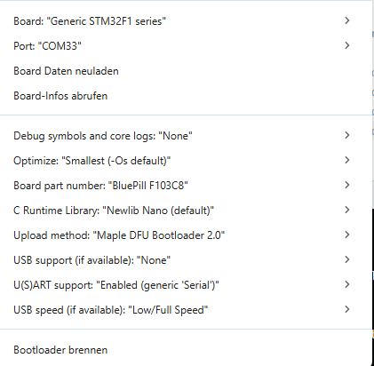
() oder F_CPU ausgegeben wird. BTW: Die Bluepill nutzt einen STM32F103C8, was dann wohl https://github.com/stm32duino/Arduino_Core_STM32/blob/main/variants/STM32F1xx/F103C8T_F103CB(T-U)/variant_PILL_F103Cx.cpp
under ordinary circumstances.” “I didn’t know that.” “Now you do,” he replied. 40 God’s Motivation “ I f you were God,” he said, “what would you want?” “I don’t know. I barely know what I want, much less what God wants.” “Imagine that you are omnipotent. You can do any- thing, create anything, be anything
3977 0.75 Y 502*B0 *502 Green Black Red 6800 3977 0.75 Y 682*B0 *682 Blue Grey Red 10 000 3977 0.75 Y 103*B0 *103 Brown Black Orange 12 000 3740 2 Y 123*B0 *123 Brown Red Orange 15 000 3740 2 Y 153*B0 *153 Brown Green Orange 22 000 3740 2 Y 223*B0 *223 Red Red Orange 33 000 4090 1.5 Y 333*B0 *333 Orange
Fälschungen geflutet. > Z.B. die Blue-Pill-Boards Nach meinem Kenntnisstand sind davon nur die STM32F103C Mikrocontroller betroffen. Aber ganz extrem, da stimme ich dir zu. Boards mit anderen gefälschten STM32 habe ich noch nicht gesehen und auch noch keinen entsprechenden Bericht gelesen.
hin, sowas besser auszunutzen. Die KI-Empfehlung: https://www.st.com/en/evaluation-tools/nucleo-f446re.html
langlebiges Pulsstrahltriebwerk Pulsstrahltriebwerke sind spätestens seit dem Erfolg der Fieseler Fi 103 eine gut etablierte Größe - in der Vergangenheit erwiesen sie sich allerdings erstens ob der kurzen Lebensdauer der Ventile und zweitens der „Rappeligkeit“ im Betrieb als kein universeller Ersatz für
Arduino F. schrieb im Beitrag #7990689: > (prx) A. K. schrieb im Beitrag #7990643: >> Yep, etwa beim Triebwerk der V1. Vor 85 Jahren. > > Das hat immerhin 1/2 Stunde durchgehalten. > Das ist Fortschritt.
einem Klon des Mikrocontroller-Transistortesters vermessen, der sagt: 20,4 nF. Ich habe- wie von Wolf17 weiter oben vorgeschlagen- C1 mittlerweile auf 220nF und C2 auf 10µF geändert.
Beitrag #8014524: > Ich habe- wie von Wolf17 weiter oben vorgeschlagen- C1 mittlerweile auf > 220nF und C2 auf 10µF geändert. Kann leider nicht mehr korrigieren. Wolf17 hat tatsächlich vorgeschlagen C1 auf 220nF zu setzen, ich habe allerdings C3 (an Pin1) auf 220nF erhöht, weil ich das aus dem
...................................................................................................103 11.3 Application of Reduce MII to MAC...............................................................................................................103 Preliminarydatasheet 6 DM8603-12-DS-P01 November8,2010
(und preismäßiger?) direkter aber modernisierter Ersatz für den F103 scheint nicht wirklich zu existieren. Ist vielleicht auch gar nicht nötig, weil die moderneren Serien die Grenzen einfach nur woanders gelegt haben aber dennoch alles abdecken. Nemopuk schrieb
I10,000 TJ=150⋅C N1000 A R T 5000 U N C 500 R 2000 25⋅C A U N 300 C 1000 I C – 200 , 500 L T =25⋅C F M 100 C h S VCE =3.0Vdc 200 –55⋅C V =3.0Vdc E IC=5.0Adc CE h 100 50 50 30 0.01 0.02 0.05 0.1 0.2 0.5 1.0 2.0 5.0 10 103 104 10 106 I ,COLLECTORCURRENT(AMP) f,FREQUENCY(Hz) C Figure 2. DC Current Gain
Environmentalspecifications Parameters Operating Non-Operating Ambient temperature 0° to 60°C (32° to 140°F) -40° to 70°C (-40° to 158°F) 20°C per hour (36°F per hour) max, 35°C per hour (63°F per hour) max, Temperature gradient without condensation without condensation 5% to 95% non-condensing 5% to 95% non-condensing
provided to check these inputs. These inputs are also separately fused on the board by 5 A fuses, F3 and F4. Additional filtering is done on each side of these sources before being applied to three-terminal regulators. There are two three-terminal regulators with + 5 V output and two more with –5 V
ing whether or not a design will work at these high edge match the characteristic impedance (Z ) 0f the line in rates and/or signal transmission rates. PCB traces order to eliminate reflection.The energy causing the behave like transmission lines and reflections occur at all reflection will now be
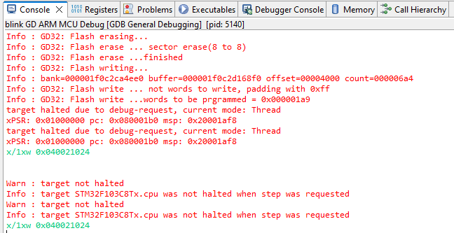
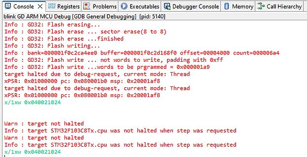
erase(8 to 8)
Info : GD32: Flash erase ...finished
Info : GD32: Flash writing...
Info : bank=000001f0c2ca4ee0 buffer=000001f0c2d168f0 offset=00004000 count=000006a4
Info : GD32: Flash write ... not words to write, padding with 0xfff
Info : GD32: Flash write ...words to be prgrammed = 0x000001a9
target
Hallo zusammen, ich arbeite an einem kleinen Projekt mit Arduino und einem STM32F103 mit integrierten CAN-Bus und komme an paar Stellen nicht weiter. Gibt es hier jemanden aus dem Raum Bayern / München, der sich mit dem STM32F103 und CAN auskennt und mir ggf. Erfahrung oder einem
Roland schrieb im Beitrag #7985089: > ich arbeite an einem kleinen Projekt mit Arduino und einem STM32F103 mit > integrierten CAN-Bus und komme an paar Stellen nicht weiter. Wo ist das Problem? Ist dir das hier bekannt? https://docs.arduino.cc/libraries/stm32_can/
Input voltage 2.7 5.5 V VOUT Output voltage V IN 38 V L Inductor 4.7 10 µH C I Input capacitor 1 µF C O Output capacitor 1 10 µF FPWM PWM dimming signal frequency 5 100 kHz D PWM PWM dimming signal duty cycle 1% 100% T Operating junction temperature –40 125 °C J 6.4 Thermal Information TPS92360 THERMAL
0xEB Register_EC data 0xEC Register_ED data 0xED Register_EE data 0xEE Register_EF data 0xEF B data 0xF0 Register_F1 data 0xF1 Register_F2 data 0xF2 Register_F3 data 0xF3 Register_F4 data 0xF4 Register_F5 data 0xF5 Register_F6 data 0xF6 Register_F7 data 0xF7 Register_F8 data 0xF8 Register_F9 data 0xF9
jetzt mit guten Erfolg auf PIC, AVR/Arduino, 8051, MSP430, Zilog Encore! und früher einmal auf STM32F103 getestet. Auch Multikanal ist möglich. Sein Konzept ist auch sehr Ressourcen schonend. Was mich betrifft, brauche ich nicht mehr über den Zaun schauen. Gerhard
verschaltet. Ich habe als Schalter einen I-0-II verwendet. Z.B.: https://www.pollin.de/p/kippschalter-kn3-c-103a-1-polig-on-off-on-420023 oder als Wippe: https://www.pollin.de/p/kippschalter-kn3-c-103a-1-polig-on-off-on-420023
Characteristics Uni-directional Bi-directional pp IT Vc VBR VR IR Vc V BRV R V V IR VR VBR Vc R V F IT T pp Ipp PPPM Peak Pulse Power Dissipation -- Max power dissipation VR Stand-off Voltage -- Maximum voltage that can be applied to theTVS without operation VBR Breakdown Voltage -- Maximum voltage
Characteristics Uni-directional Bi-directional pp IT Vc VBR VR IR Vc V BRV R V R V IR VR VBR Vc T V F IT pp Ipp PPPM Peak Pulse Power Dissipation -- Max power dissipation VR Stand-off Voltage -- Maximum voltage that can be applied to theTVS without operation V Breakdown Voltage -- Maximum voltage that
configurat ion, reset 9121, leave configuration mode STM32 The sample demo we provide is based on STM32F103RBT6, and the connection method provided is also the pin of the corresponding STM32F103RBT6. If there is a need to transplant the demo, please connect according to the actual pin. Hardware Connection STM32F103ZET connection pin correspondence ETH STM32 5V 5V GND GND RXD1 PC10 TXD1 PC11 CFG0 PC12 RST1 PD2 Take our STM32F103RBT6 as an example, the connection is as follows: 2-CH UART TO ETH-STM32.png (/wiki
Supply Voltage 6 9 10 V V Max. inputsignal handling 2 Vrms CL THD Total Harmonic Distortion V = 1Vrms f = 1KHz 0.01 0.1 % S/N Signal to Noise Ratio 106 dB S C Channel Separation f = 1KHz 103 dB Volume Control 1.25dB step -78.75 0 dB Bass and Treble Control2db step -14 +14 dB Fader and Balance Control1.25dB
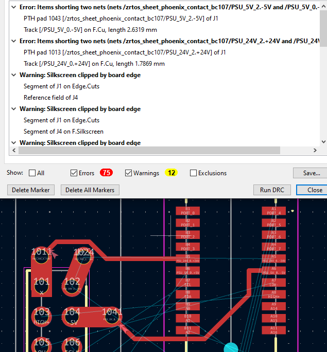
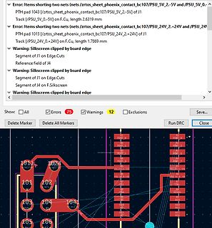
/zrtos_sheet_phoenix_contact_bc107/PSU_5V_2.-5V and /PSU_5V_0.-5V) of J1 Track (/PSU_5V_2.-5V) on F.Cu, length 2.6319 mm
Error: Items shorting two nets (nets /zrtos_sheet_phoenix_contact_bc107/PSU_24V_2.-24V and /PSU_24V_1.-24V) of J1 Track (/PSU_24V_0.-24V) on F.Cu, length 1.7869 mm
Warning: Silkscreen
1503 fehlt, sollte 150k sein ! R27 1503 tot, sollte 150k sein ! R28 1202 hat 12k, richtig ? R52 103 tot, sollte 100k sein ? R58 103 hat 16k, richtig ? R59 203 tot, sollte 20k sein ? SS80050 NPN für Lüfter tot, Collector abkorrodiert https://www.onsemi.com/pdf/datasheet/ss8050-d.pdf Max. 40V VCB
Fred F. schrieb im Beitrag #7976337: > R27 1503 tot, sollte 150k sein ! Ja 150 000 Ohm > R28 1202 hat 12k, richtig ? Ja 120 00 Ohm > R52 103 tot, sollte 100k sein ? Nein 10 000 Ohm > R58
Als Suchbegriff wäre "EEPROM" sinnvoll; vorab, ja, die Dinger werden senil. mfG fE
Scheint es doch noch als Ersatzteil zu geben. Lieferzeit 3 Tage: https://e.cybelec.ch/shop/s-nlr-me103dmo-nlr-board-for-measurement-points-per-rsr232-2538?page=3&category=6#attr=
Material Metal shell, thermoplastic case Temperature Extended Temp RoHS product: -40°C to +85°C (-40°F to 185°F) Storage range: -40°C to +85°C (-40°F to 185°F) Relative Humidity Operating: 5% to 95% non-condensing Shock/Vibration Non-operational shock: 500 g's, Non-operational vibration: 20 g's Warranty
Material Metal shell, thermoplastic case Temperature Extended Temp RoHS product: -40°C to +85°C (-40°F to 185°F) Storage range: -40°C to +85°C (-40°F to 185°F) Relative Humidity Operating: 5% to 95% non-condensing Shock/Vibration Non-operational shock: 500 g's, Non-operational vibration: 20 g's Warranty
-A118A Condition A *Tests are preceded by MSL3 preconditioning in accordance with JEDEC JESD22-A113F Table 55.Component Level Tests Test Condition Qty/lot Lot Acc/Rej Result Preconditioning(MSL3) 24hrs HTSL (125C) ->192Hrs WHTSL 77 3 0/1 PASS (30C/60%RH) + 3x PbFree Reflow, 260C max JEDEC JESD22-A113F
xc68hc711E20cfn_8MHz] Test: > L 0 -> liest 16 bytes ab RAM Adresse 0 > L 0 2ff -> liest das gesamte RAM > l 1000 103f -> liest alle Control Register > l B600 B7FF -> liest das gesamte EEPROM > l 9000 AFFF -> liest die unteren 8k des OTP EPROMS > l d000 ffff -> liest die oberen 12k des OTP EPROMS Hinweis: MemMap711E20
. Unterstützt eine Vielzahl von PIC-Chips und wird ständig erweitert. Derzeit können PIC10F, PIC12F, PIC16F, PIC18F, PIC24H sowie dsPIC30F und dsPIC33F programmiert werden. InCircuit-Programmer und -Debugger (www.stolz.de.be) Einfacher Nachbau des Microchip ICD2s. Zum Programmieren und Debuggen
und Pinguino Wiki ist ein Arduino-ähnliches Open Source und Open Hardware Projekt für 8-Bit (PIC18F2550, PIC18F4550) Mikrocontroller. Entwicklungsboard auf Grundlage des PIC18F25K22 - Sehr gut geeignetes Entwicklungsboard für Einsteiger und Fortgeschrittene Z8. Yahoo! Groups : z8encore Yahoo-Gruppe
board). 4- Check connections on induction modules. Replace the module that controls the zone with F0. F2 TouchControl Extended operation of the 3- Leave to cool. The areas affected by this error may overheating. coils near the not operate during a short period of TouchControl. Above > time. Once the
f f f f f f 1 Z Increment "f" INCXSZ f, d f f00 1111 df f f f f f f1 or 2 - Increment "f", skip if zero IORWX f, d f f00 0100 df f f f f f f 1 Z OR W with "f" MOVX f,d f f00 1000 df f f f f f f 1 Z Move "f" MOVXW f f f00 1000 0f f f f f f f 1 Z Move "f" to W MOVWX f f f00 0000 1f f f f f f f 1 - Move W to "f" RLX f, d f f00 1101 df f f f f f f 1 C Rotate left "f" through carry RRX f, d f f00 1100 df f

 Bild
Bild
 Bild
Bild
 Bild
Bild
 Bild
Bild
 Bild
Bild
 Bild
Bild
 Bild
Bild
 Bild
Bild