8 GND Figure 27 Interface to 8-bit Microcomputer 41 HD66766R Rev. 1.0-1 / September 2002 Note: Transfer synchronization function for an 8-bit bus interface The HD66766R supports the transfer synchronization function which resets the upper/lower counter to count upper/lower 8-bit data transfer in the
zusätzlichen HDMI Grabber Daten gestreamt. Im Projekt steht: [code] Sample 16 GPIOs with the PIO and transfer the data, can be used as a 16 bit @ 32 MHz logic analyzer, or be adapted to 8 bit @ 64 MHz and so on. [/code] In dem Link von mir verwendeten sie USB. Nicht als Stream. Dafür mit bis zu 120 Kanälen
the case does not contact power line of other circuits. It is believed that the use of optical transfer devices improve the noise resistance. In principle, optical fiber is not affected by noise. However, especially receiving module which handle signals whose level is extremely small, are comparatively
something like that. ESP has to have some cause.” “If you define ESP narrowly to include only the transfer through the air of information, then skeptics will never detect it,” he said. “But if you accept luck as being the same as ESP, then ESP exists and it can be useful, though not reli- ably so, since
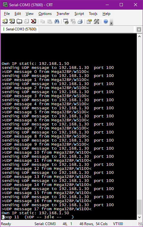
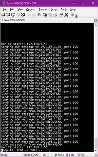
Serial-COM3 (57600) - CRT
File Edit View Options Transfer Script Tools Help
| Serial-COM3 (57600)
own IP static: 192.168.1.50
sending UDP message to 192.168.1.30 port 100
>UDP message 0 from Mega328P/w5100<
sending UDP message to 192.168.1.30 port 100
>UDP
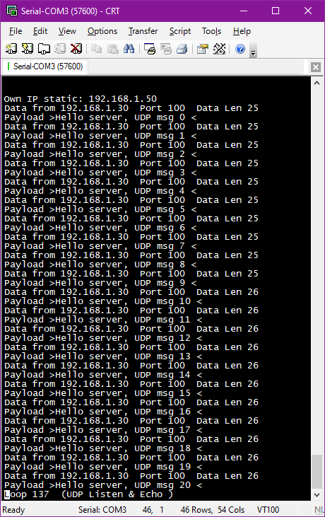
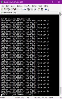
Serial-COM3 (57600)
File Edit View Options Transfer Script Tools Help
Own IP static: 192.168.1.50
Data from 192.168.1.30 Port 100 Data Len 25
Payload >Hello server, UDP msg 0 <
Data from 192.168.1.30 Port 100 Data Len 25
Payload >Hello server, UDP
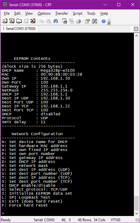
Serial-COM3 (57600) - CRT
File Edit View Options Transfer Script Tools Help
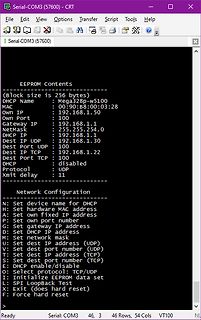
EEPROM Contents
(Block size is 256 bytes)
DHCP Name : Mega328p-w5100
MAC : 00:90:B8:00:03:28
Own IP : 192.168.1.50
Own Port : 100
Gateway IP : 192.168.1.1
NetMask : 255.255.254.0
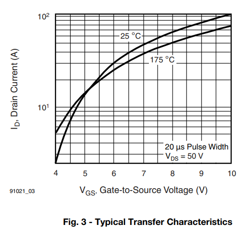
A temperature stability and performance. n Laser trimmed thick film resistors on the a TYPICAL TRANSFER CHARACTERISTICS o ceramic substrate and thin film resistors g on the integrated circuit reduce null and gainshiftsovertemperaturewhichresults in consistent sensitivity from one device to the next.
protect the IC during overloads and extreme ambient b feedback resistor R 1ontributes in the device transfer temperatures. function as an additional zero and affects the device loop stability, therefore its value must be optimized. Attention Regulator to the Output Capacitor value and its ESR must be paid
TXCLK/ O, Transmit Clock ISOLATE Z, The transmitting clock provides the timing reference for the transfer of the LI TXEN, TXD, and TXER. TXCLK is provided by the PHY (D) 25MHz in 100Mbps nibble mode, 2.5MHz in 10Mbps nibble mode, 10MHz in 10Mbps GPSI (7-Wired) mode ISOLATE Setting: 0: Reg 0.10 will be
clock) from the external device is a continuous clock that provides the timing reference for the transfer of the P2_TXE, P2_TXD3~0. The DM8603 can drive 25MHz clock if it is configured to reversed MII mode. • P2_TXE (transmit enable) from the DM8603 port 2 MAC indicates that nibbles are being presented
configured to reversed MII mode. device is a continuous clock that provides the timing reference for the transfer of the TXE2, TXD2. The 9.3.2 MII Serial Management DM8203 can drive 25MHz clock if it is configured to The MII serial management interface consists of a reversed MII mode. data interface, basic register
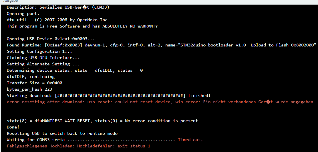
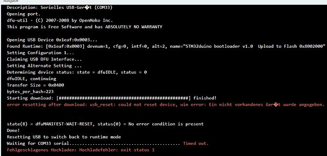
Alternate Setting ...
Determining device status: state = dfuIDLE, status = 0
dfuIDLE, continuing
Transfer Size = 0x0400
bytes_per_hash=223
Starting download: [########################################] finished!
error resetting after download: usb_reset: could not reset device, win error: Ein nicht vorhandenes
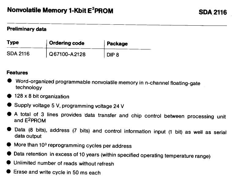
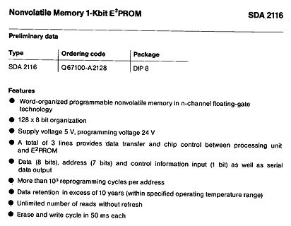
bit organization
Supply voltage 5 V, programming voltage 24 V
A total of 3 lines provides data transfer and chip control between processing unit and E2PROM
Data (8 bits), address (7 bits) and control information input (1 bit) as well as serial data output
More than 10^3 reprogramming cycles per address
etwas "na ja"; letzendlich wird in i2c_write_dt() wohl i2c_write() aufgerufen, was wiederum i2c_transfer() aufruft und letztendlich die -5 liefert.
> Ursache sind wohl vergessene Pull up. Oder ein Bug in der Treiberroutine, hier also in i2c_transfer(). Muss so sein, hast du ja selbst durch Messung/Funktionsprüfung festgestellt. Also: Man muss sich anschauen, was i2c_transfer() wohl falsch macht. Wobei dabei natürlich durchaus herauskommen
Bits) from DSP Eye Data In Serial Input from Eye Data Start Eye Sample Eye Data Clock Left Data In Transfer Transfer Clock Left Data Start Control Left Data End Serial Input Start Flag Right Data In fromADCs Right Data Start orAES/EBU Data (8 Bits) Right Data End Receiver Bit Clock Control (10 Bits) Left
the further their separation in the series, seen in the field. the stronger is the tendency to transfer charge. There are three such models in vogue. The first is the One can also get ESD when peripherals are plugged most popular and is referred to as the Human Body into a system. This can take place
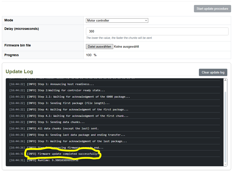
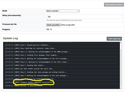
data chunks (except the last) sent. [16:44:26] [INFO] Step 6: Sending last data package and ending transfer... [16:44:26] [INFO] Step 7: Waiting for acknowledgment of the last package... [16:44:26] [INFO] Step 8: Announcing firmware update end... [16:44:31] [INFO] Firmware update completed successfully!
Verlauf zeigt, dass das CTR mit höherem Strom noch deutlich ansteigt (z.B. DS Liteon Fig.5 Current Transfer Ratio vs. Forward Current). Diese ganze Bastelei mit dem Kondensator ist eine Krücke. Der ESP wird es doch wohl schaffen, im Maximum der Halbwelle abzutasten und fertig. Bisher hat auch noch keiner
e-nt control part,effectively ensuring the pixel point light color height consistent. The data transfer protocol use single NZR communication mode. After the pixel power-on reset, the DIN port receive data from controller, the first pixel collect initial 24bit data then sent to the internal data latch
ATM steht fuer Asynchron Transfer Mode. D.h. das Protokoll arbeitet heute das asynchronene Aufkommen des Datenverkehrs ab. Leider klickt ja niemand synchron im Browser. Also Dieter die erste Sekunde jeder Minute, A K jede zweite,
Dieter D. schrieb im Beitrag #7986796: > ATM steht fuer Asynchron Transfer Mode und galt vor über 30 Jahren als DAS zukünftige Übertragungsverfahren für Daten UND Sprache, bevor es kurz danach in der Versenkung verschwand. Dieter D. schrieb im Beitrag #7986796: >
22.170 [ms] (mean) Time per request: 22.170 [ms] (mean, across all concurrent requests) Transfer rate: 7.75 [Kbytes/sec] received [/pre] Danach habe ich ab(1) 50.000 Requests mit einer Concurrency von 16 aufgerufen und die Ergebnisse aus wie ich hoffe verständlichen Gründen verworfen
11.681 [ms] (mean) Time per request: 11.681 [ms] (mean, across all concurrent requests) Transfer rate: 14.71 [Kbytes/sec] received [/pre] Du siehst, sogar in diesem einfachen Fall kann der JIT-Compiler die Laufzeit halbieren, wenn er die "heißen Pfade" im Code gefunden hat. Wobei
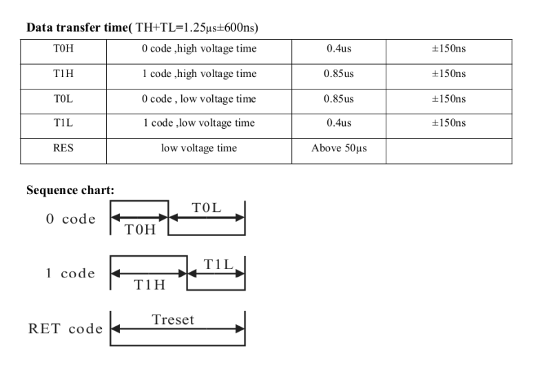
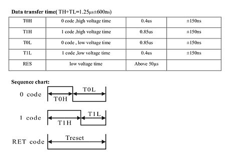
Data transfer time(TH+TL=1.25µs±600ns)
T0H 0 code,high voltage time 0.4us ±150ns
T1H 1 code,high voltage time 0.85us ±150ns
T0L 0 code, low voltage time 0.85us ±150ns
T1L 1 code,low voltage time 0.4us ±150ns
RES
11 431 16 070 Output capacitance C oss V GS = 0 V VDS = 25 V, f = 1 MHz - 4772 6681 pF Reverse transfer capacitance C rss - 327 458 Total gate chargec Q g - 183 275 Gate-source charge c Qgs VGS = 10 V V DS= 30 V, ID= 50 A - 53 - nC c Gate-drain charge Q gd - 42 - Gate resistance R g f = 1 MHz 0.7 1.4
gedacht du kannst bereits Schaltpläne lesen. ...tatsächlich kann ich das einigermaßen - es ist der Transfer von Papier zu Kupfer der mir Probleme bereitet. Alles in allem habe ich es zwar etwas spät bemerkt, aber hier stehen ja bereits alle Infos die ich brauche :-) Vielen Dank an alle Beteiligten
address buses in relation to the 6502. DMA is used by peripheral cards in the Apple II family to transfer data directly into memory without benefit of the processor. Transfer of data from a peripheral device into RAM can normally be handled one byte at a time under control of the processor. By using DMA, you can achieve greater data transfer rates than the 6502 can handle in software. This transfer rate can approach the full-cycle time of the memory. This technique can also be used to transfer single data bytes into memory without requiring
compensation design is to shape the 3. Determine if the second compensation capacitor converter transfer function to get a desired loop gain. (C4) is required. It is required if the ESR zero of The system crossover frequency where the feedback the output capacitor is located at less than half of loop
of the soldered joint, um so eine optimale Wärmeübertragung zu thereby guaranteeing optimum heat transfer. gewährleisten. Wählen Sie den Innendurch- Select the inside diameter of the desoldering tip messer der Entlötspitze so, daß ein kleiner Ring- so there is a small ring-shaped gap of approx. spalt
adhesive can be The device may be mounted up to the seating plane, but applied by screen printing, pin transfer or syringe the temperature of the plastic body must not exceed the dispensing. The package can be soldered after the specified maximum storage temperature (T stg max. If the adhesive is cured. printed-circuit
case the master transmitter can gen- line is LOW. erate the STOP information in order to abort the transfer. Startand Stop Conditions As shown in fig.18 a start condition is a HIGH to LOW transition of the SDA line while SCL is TransmissionwithoutAcknowledge HIGH. The stop conditionis a LOW to HIGH tran
post-irradiation up to 100 krad(Si) and single effect effects (SEE) characterized up to a linear energy transfer (LET) of 81.9 MeV·cm2/mg. RIC70847 is available in a hermetically sealed 24-lead flatpack and operates over the full military ambient temperature range of -55°C to 125°C [/c] ### Ohmite 900 -
eine Ankündigung von Renesas interessant sein, die nach folgendem Schema neue Bauteile mit höherer Transfer-Geschwindigkeit ermöglichen soll: [c] 10% Bandwidth Increase over Renesas’ Gen5 RCD (9600 MT/s versus 8800 MT/s) Backward Compatibility with Gen5 Platforms: Provides seamless upgrade path
switching cycles. This is especially important when the converter is lightly loaded. Figure 6. IFB transfer function It is then possible to build the total DC transfer function between I and I as shown on D FB Figure 6 on page 10. This figure also takes into account the internal blanking time and its associated
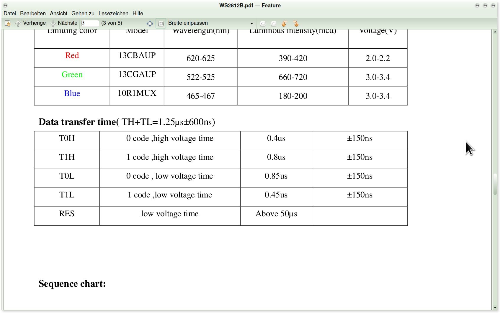
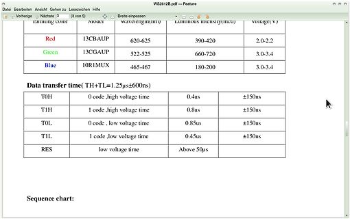
390-420 2.0-2.2
Green 13CGAUP 522-525 660-720 3.0-3.4
Blue 10R1MUX 465-467 180-200 3.0-3.4
Data transfer time( TH+TL=1.25µs±600ns)
T0H 0 code, high voltage time 0.4us ±150ns
T1H 1 code, high voltage time 0.8us ±150ns
T0L 0 code, low voltage time 0.85us ±150ns
T1L 1 code, low voltage time 0.45us ±150ns
VOLTAGE CONTROL LOOP FREQUENCY FIGURE 24. FREQUENCY RESPONSE OF THE LC OUTPUT FILTER Output LC Filter Transfer Functions The gain from the phase node to the system output and battery depend entirely on external components. Typical output LC filter response is shown in Figure 24. Transfer function LC(s) is
.........................................................................13 Table 11.Transfer when master is receiving (reading) one byte of data from slave.................................................13 Table 12.Transfer when master is receiving (reading) multiple bytes of data from slave
Codierung > eine Webseite benutzt. Bei statischen Dateien: für den Header und ggf. bei Ascii 7-bit-Transfer (war zumindest in der IT-Steinzeit mal so). In diesem Fall alles irrelevant. Hans schrieb im Beitrag #7973002: > Du hast sowas schon mit Embedded gemacht? Ich würde jetzt nicht gerade einen
coating on insulated floors. Electronic devices with components that are sensitive to People can transfer an electrostatic voltage: electrostatic shock (EGB in German) are marked with the pictogram shown here. of up to 35,000 volts when standing on a non-conductive carpet. of up to 12,000 volts when standing
register pairs must be carried out in a specific way. The important point to notes is that data transfer to and from the 8-bit buffer and its related low byte only takes place when write or read operation to its corresponding high bytes is executed. Briefly speaking, write low byte first and then high
register pairs must be carried out in a specific way. The important point to notes is that data transfer to and from the 8-bit buffer and its related low byte only takes place when write or read operation to its corresponding high bytes is executed. Briefly speaking, write low byte first and then high

 Bild
Bild
 Bild
Bild
 Bild
Bild
 Bild
Bild
 Bild
Bild
 Bild
Bild
 Bild
Bild

 Bild
Bild
 Bild
Bild
 Bild
Bild
 Bild
Bild
 Bild
Bild
 Bild
Bild
 Bild
Bild