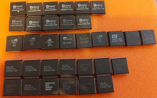
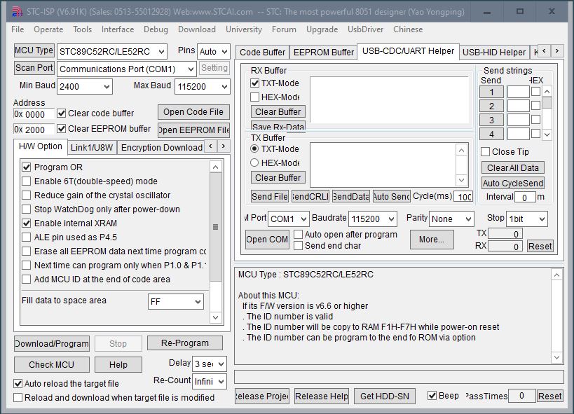
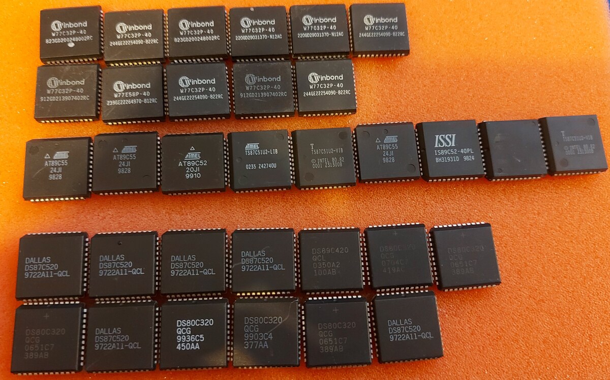
Moin, ich habe eine mir nützliche Ausschlacht Controllerboard mit einem STC89C52RC drauf und will etwas damit machen und lud mir dafür die ISP Software V6.91 von der Herstellerseite herunter: https://www.stcmicro.com/rjxz.html Daraufhin checkte ich die SW mit einem Viren
empfand, daß die ISP SW die uV2 Target Liste auf STC erweiterte. Ich kompilierte eines meiner alten AT8051er Programme ohne irgendwelche Probleme seitens uV2. Eines muß ich allerdings erst untersuchen. Der Designer der RBC-1200 Bord legte den RESET-Pin direkt auf Masse. Bis jetzt konnte ich durch
ReadthetemperaturedataintheADCdataregister,andcalculatethetemperaturevalue bythefollowingformula: Temperature (° C) = {( V - V ) /Avg_Slope} + 30- T 30 SENSE offset In which: V 30V SENSE at 30 degrees celsius Avg_Slope = temperature andAverage slope of a V SENSE curve (mV/°C or μV/°C) T offsetempirical value for
the antenna design guide and to the specific application notes for the reader IC. R1 1 OEMBoard 2 C1 LANT C3 5 C6 6 C5 C4 C8 C2 R2 6.1.3.3 Serial Interface The OEM Board can be connected directly with a micro controller. Alternatively the OEM Board also can be connected to most serial interface types
and C223 form part of the ‘Zobel’ network that ensures the amplifier sees a constant load of roughly 4.7Ω at very Optocoupler IC300C is connected in series with the 3 optocouplers high frequencies. This helps
Kestler, DK1OF 1975/2 66 - 77 Description 70 cm Band A Simple 70 cm Power Amplifier Equipped with the 2C39 K Weiner, DJ9HO 1975/2 78 - 82 70 cm Band A Versatile 70 cm Converter with Schottky Diode Mixer B Lubbe, DJ5XA 1975/2 83 - 89 Amateur Television A Veratile 70 cm Converter with Schottky Diode Mixer
Copyright: Shenzhen Tian Microelectronics * File name: TM1637 * Current Version: 1.0 * SCM Model: AT89S52 * Development Environment: Keil uVision3 * Crystal earthquake frequency: 11.0592M * Program features: the TM1637 all filled with all the display data register address 0xff, and open the display
Holger R. schrieb im Beitrag #7684399: > Ich dachte es wäre ein Standart I2C Bus. Da kannst du stehen, wie es deine Art ist, aber das Datenblatt zum TM1637 sagt: "Note: The communication method is not equal to 12C bus protocol totally because there is no slave address" (S
1.3V to 3.6V X1 1 10 VCC • Low Typical Timekeeping Current: X X2 2 5 9 MFP - Operating from V: 1.2 µA at 3.0V 9 - Operating from VT: 1.0 µA at 3.0V VBAT 3 P 8 SCK • Automatic Switchover to Battery Backup CS 4 C 7 SO M VSS 5 6 SI User Memory • 64-Byte Battery-Backed SRAM • 1 Kbit or 2 Kbit EEPROM: Note:
time to get to level 6 (except S9, which had data, and should be considered unreliable [77]. A chip at this state only reached 5 at the camera-ready due date); we took every device could stop functioning at any moment. all the way to 11, except the S6 and S9. Timing results vary, even We repeatedly issued
S 2.5 4 - 56 mm c 14 mm purpose tape feeding modules c which are equally suitable for pa- 1 x 72 mm S 3 4 - 72 mm c 14 mm per and blister tapes, a small range 1 x 88 mm S 3 4 - 72 mm 14 mm of module types will be sufficient
P89C52UFBB P89C52UFBB 89C52 QFP IND 935262570551 T M 3 31-12-00 30-6-01 P87C52UFBB Standard Discontinuation P89C52UFBB P89C52UFBB 89C52 QFP IND 935262570557 T M 3 31-12-00 30-6-01 P87C52UFBB Standard Discontinuation P89C52UFPN P89C52UFPN 89C52 DIP IND 935262569112 T M 3 31-12-00 30-6-01 P87C52UFPN Standard Discontinuation P89C54UBBB P89C54UBBB 89C54 QFP COM 935262610557 T M 3 31-12-00 30-6-01 P87C54UBBB Standard Discontinuation
A DATA A DATA A P W R AcknowledgefromRV-3032-C7 May 2023 124/154 Rev. 1.3 Micro Crystal DTCXO Temp. Compensated Real-Time Clock Module RV-3032-C7 6.8. READ OPERATION AT SPECIFIC ADDRESS Master reads data from slave RV-3032-C7 at specific address:
the I2C 2002-1A Evaluation Board Kit at www.demoboard.com DesignCon 2003 TecForum I C Bus Overview 89 Slide 89 2 Low Power version of the SMBus Specification only Comparison of I C with SMBus The SMBus specification
of a device of the series contains information as depicted below: Figure 1-2. Device Designations AT tiny1617 - MNR Carrier Type Package up to 24 pins R=Tape & Reel Flash size in KB Temperature Range tinyAVR series N=-40°C to +105°C F=-40°C to +125°C Pin count Package Type 7=24 pins M=QFN 6=20 pins
selbst, vier LED-Displays mit gemeinsa- mer Kathode (TLR 324 von Toshiba) und einem Mikrocontroller AT89C2051 von Atmel(eswärenauchandereTypendenk- bar) istnur noch ein Temperatursensor er- forderlich. Der dafür gewählte LM75 von National Semiconductor passt sehr gut zum Rest der Elektronik, da er ebenfalls
NOTICE. THE PRODUCTS DESCRIBED HEREIN AND THIS DOCUMENT ARE SUBJECT TO SPECIFIC DISCLAIMERS, SET FORTH AT www.vishay.com/doc?91000 VS-E5PH6006L-N3 www.vishay.com Vishay Semiconductors 1000 C 180 ) ( p r 170 ( t c r 160 a e i m a e 150 a T DC C 100 a 140 n P t e 130 c l u S 120 Square wave (D = 0.50) - e
pins, two on each side of the connector. To avoid confusion, the first two pins are defined as Pin C0 and Pin D0. The additional ground pins at the end of the connector are defined as C19 and D19. The pinout between PC/104 bus and AT ISA bus is identical between C1 - C18 and D1 - D18. The MOPS/386A
fixed on the front side or on the bottom of the tank. The preset switch-off temperature is approx. 60°C. If the temperature rises above 70°C during operation without cover (contact permanently closed), or if the unit does not heat at all (contact permanently opened), the thermostat is probably faulty.
- Time (ms) Fig. 1 - Peak Pulse Power Rating Curve Fig. 3 - Pulse Waveform )P 100 6000 IP Measured at t ) Zero Bias e p r , 75 e C ge c1000 r t t ) e c P r p ( P 50 a e n C w g i V , Measured at Stand-Off P t c 100 Voltage V e r u WM l e 25 - P D J Uni-Directional TJ= 25 °C k C Bi-Directional f = 1.0
controls, gate drivers for larger thyristors, and sensing and 1 1 detection circuits. FEATURES SOT-89 TO-92 * Sensitive gate allows triggering by micro controllers and other logic circuits * Blocking voltage to 600V * On-state current rating of 0.8A RMS at 80C * High surge current capability – 10A *
nicht erfolgreich: Die gemessene Motorinduktivität ist zu niedrig. 43 2B DA1, DB1, DC1 AtF-04 Motor-Identifikation nicht erfolgreich: Die gemessene Motorinduktivität ist zu groß. 44 2C DA1, DB1, DC1 AtF-05 Motor-Identifikation nicht erfolgreich: Die gemessenen Motorparameter passen nicht
bitten/betteln wird auf Dauer einen zermürben. Meine längste Suche nach einem Assemblerbug (war aber AT89C52) lag bei ein paar Wochen mit vielen Unterbrechungen – am Ende waren es zwei Bitverschiebungen, die die Bits auf der anderen Seite wieder eingeschoben haben (allgemein als ROR/ROL bekannt), was ich
daraus: deren Mehrfachverwendung für völlig unterschiedliche Zwecke. Aber das hat C++ natürlich von C geerbt, betrifft also C weitestgehend genauso.
Anbei Schaltplan, Code, Hex für AT89C2051. Sollte sich problemlos auf einen ATtiny25 anpassen lassen.
Dann würde sich C2 direkt über DIS entladen und der low-Puls wäre entsprechend kurz. Das finde ich nicht allzu galant.. Aber apropos Kondensator, kann ich C1 auch mit 100n bestücken? Auf dem Prototyp tut sich nichts
connected to SS BS0, BS2, CL, D[7:3], E, R/W#, CS#, D/C#, BGGND Pin internally connected to DD: BS1, CLS V BAT,C1P, C1N, C2P, C2N, V BREF, FR should be left open. C1, C2: 2.2uF (1) (1) C3: 1.0uF R P Pull up resistor Voltage at REF = VCC – 2.5V. For VCC= 7.5V
Software benutze ich „AVRDUDE“ Version 7.1 mit Erweiterung von avrdue.conf für die Mikrocontroller AT89S51/52 [code] avrdude -c usbasp -p 8052 -U flash:r:test.hex:i avrdude warning: a1 would normally be expected to be a9 [E:\Baben\Dokumentation\ELEKTRO\Mikrokontroller\ATmega\AT89S51 flashen\Software
Datenblatt des AT89S52 kann man Reset zum Programmieren wohl auch einfach auf Vcc setzen.
https://www.n2yo.com/?s=47853&fbclid=IwAR0Nu7Q6QjezaC3C-VNMQQpgYT-CtGZfJjXTZy1tEc0hmRds1sa9TEQk4D0 Das große Radioteleskop in Wachtberg müsste das eigentlich gut sehen, die erkennen ja noch viel kleinere Objekte.
fliegt das Trum nicht mehr. Es ist unten. Ab einer Resthöhe von 136km ging es schnell abwärts (20:52 UTC).
ausgebauten Übertragungsnetz und damit auch zur Vermeidung von Engpassmanagement bei. BUNDESNETZAGENTUR | 89 Prüfungsergebnisse DC40plus A 2037 B 2037 C 2037 Überlastungsindex - 540 GWh - 950 GWh - 1170 GWh Leistungsfluss Maximum 2000 MW 2000 MW 2000 MW Auslastung 100 % 100 % 100 % A 2045 B 2045 C 2045 Überlastungsindex
at core/timeouts.c line 241 0x40201047: updatePWM() at C:\Users\alex\Documents\Arduino\OhneFehler/OhneFehler.ino line 54 0x402014f4: Ticker::_static_callback() at C:\Users\alex\AppData\Local\Arduino15
0x401000ab: app_entry_redefinable() at C:\Users\alex\AppData\Local\Arduino15\packages\esp8266\hardware\esp8266\3.1.2\cores\esp8266\core_esp8266_main.cpp line 386 0x4010015c: ets_post(uint8, ETSSignal, ETSParam) at C:\Users\alex\AppData\Local
Peter D. schrieb im Beitrag #7603117: > Dabei gibt es durchaus leistungsfähige 8051, z.B. AT89LP51RD2 (20 MIPS). Lahme Gurke! ;-) https://www.silabs.com/mcu/8-bit-microcontrollers/c8051f12x-f13x
CODE (?C_START) PUBLIC ?C_STARTUP CSEG AT 5000h ?C_STARTUP: LJMP STARTUP1 [/C] Beim SDCC hättest du übrigens genau das das gleiche Problem auch der linkt

 Bild
Bild
 Bild
Bild