respective contributors. They do not constitute TI specifications and do not necessarily reflect TI's views; see TI's Terms of Use. TI E2E™ Online Community TI's Engineer-to-Engineer (E2E) Community. Created to foster collaboration among engineers. At e2e.ti.com, you can ask questions, share knowledge
EFUSE_RD_RS_ERR0_REG (0x01C0) M NM L _N FA M ER_ NU NU NU NM FA NM _A ER M_ _U M_ FI R_ FI ER_ A ER FA R_ AT_ ER RT AT_ PI R1 PI8 Y3 Y_ Y2 Y3 Y_ Y2 Y_ Y1 RD Y_ S_A RD C_ S_P CS _E _K _KE _E _K _E _K _KE _S _K _Y _U _A _Y vd) _A US USE UE US UE US USE UE US UE US USE UE US sr US E EF E EF E EF EF E EF E EF EF
completed within a delay of RESET afterV PPreaches2.0V(seeTable 8).Duringnormaloperation,V PP must be held at a logic high (2.4 V minimum) or tied to thePPsupply (12.0 V) for EPX8160 devices. Table 8. Reset Characteristics Symbol Parameter Value Conditions t JTAG reset time 150 s maximum Software control RESET
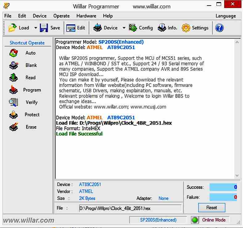
Device Operate Hardware Help Language Load Save Edit Device Config Info Settings Programmer Model: SP200S(Enhanced) Device Model: ATMEL AT89C2051 Willar SP200S programmer, Support the MCU of MCS51 series, such as ATMEL / WINBOND / SST etc., Support 24 / 93 Serial memory of many companies, MCU ISP download
_ NUMBER 000D ??_AT89LP51RD2_ NUMBER 000F ??_AT89LP51_ NUMBER 0007 ??_AT89LP52_ NUMBER 0008 ??_AT89LP6440_ NUMBER 000B ??_AT89LP828_ NUMBER 0009 ??_AT89LS51_ NUMBER 0019 ??_AT89LS52_ NUMBER 001A ??_AT89S2051_ NUMBER 0012 ??_AT89S4051_ NUMBER 0013 ??_AT89S51_ NUMBER 0014 ??_AT89S52_ NUMBER 0015 ??_AT89S53_ NUMBER 0016 ??_AT89S8252_ NUMBER 0017 ??_AT89S8253_ NUMBER 0018 ??_DEFAULT_ NUMBER 0000 AC BIT D6 ACC DATA E0 ADD1 NUMBER
ASEM-51 V1.3 Copyright (c) 2002 by W.W. Heinz PAGE 1 MCS-51 Family Macro Assembler A S E M - 5 1 V 1.3 ===================================================== Source File: C:\Users\BNoll\Documents\Mide51\MM\MM2
Guten Tag, ich suche einen Assembler + Linker für die Mikrocontroller der Atmel-Familie (AT89C51, AT89S51/52). OS = WINDOWS 10/11. Ich möchte zwei Assembler-Dateien zusammenfügen (main.asm + function.asm). Ich habe dafür Keil-C verwendet, leider habe ich aber nur die Eval-Funktion mit der
> Guten Tag, > ich suche einen Assembler + Linker für die Mikrocontroller der > Atmel-Familie (AT89C51, AT89S51/52). OS = WINDOWS 10/11. > Ich möchte zwei Assembler-Dateien zusammenfügen (main.asm + > function.asm). > Ich habe dafür Keil-C verwendet, leider habe ich aber nur die > Eval-Funktion
. Jetzt ist eben die Frage, ob man an weitere Informationen herankommt, bspw. die Firmware des AT89C2051 (s. Beitrag von Dieter) oder eine Aufzeichnung der RS-232-Daten (s. mein letzter Beitrag). Stellt sich beides als unmöglich heraus, bleibt nur zu hoffen, dass es sich um ein ganz primitives
geschrieben und man muss auch beim SRAM auf den Verbrauch achten (musste ich damals auch, ich habe aber den AT89C4051 genommen und für größere Projekte den AT89C52), was mit so einer Kompaktheit des Protokolls im Einklang wäre, falls das wirklich der UART-Eingang für die Übertragung der Displaydaten ist, denn
the second coil. We can rearrange (2.9) into a somewhat simpler form by noting that n ∗i =2J ∗2 . T2at i2, the total amps times turns for the second coil equals the current density in the second coil times the second coil’s cross-section area. Substituting for J 2n (2.9) yields: ▯ ▯ n2 Z Z L mutual= A
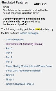
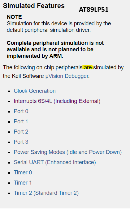
Simulated Features
AT89LP51
NOTE
Simulation for this device is provided by the default peripheral simulation driver.
Complete peripheral simulation is not available and is not planned to be implemented by ARM.
The following
uVision Debugger (5.38.00 Eval Version) kommt in der Simulation nicht mit PowerDown klar, wenn ich den AT89LP51RB2 als Device verwende. Diese simple Loop kann ich im Single Step (F11) durchgehen, obwohl beim PCON |= 2 die Simulation sofort anhalten sollte, weil die Clock steht. [code] int count = 0; void
Aussagen von Keil zu den beiden Chips. Daraufhin hatte ich angenommen, PD geht in der Simulation beim AT89LP51.
https://www.silabs.com/developers/keil-pk51 Du kannst bei Silabs / Keil auch eine vollwertige Keil Lizenz bekommen.
sowieso nicht möglich ist, werde ich auch nicht versuchen, da durchzusteigen. Habe mir jetzt den Atmel AT89LP51RB2 ausgesucht, ist bei Mouser verfügbar. Der wird ordentlich von Keil supportet und kann weit mehr, als ich benötige. Zumindest konnte ich schon erste Simulationen erfolgreich durchlaufen.
IRLML2502PbF Micro3 (SOT-23) (Lead-Free) Package Outline Dimensions are shown in millimeters (inches) S M DIMENSIONS 6 B MILLIMETERS INCHES D 5 L MIN MAX MIN MAX A 0.89 1.12 .036 .044 A1 0.01 0.10 .0004 .0039 A2 0.88 1.02 .035 .040 3 6 E b 0.30 0.50 .0119 .0196 E1 c 0.08 0.20 .0032 .0078 ccc C B A D 2.80
Black wire Insulation Drain wire Clear wire 44531 IMPORTANT Ground the drain wire and foil shield at field side. WiringExamples Examplesof sink/source, input/output wiring areshown below. Sink output wiring example User side +V DC Fuse Logic side D OUT Load + G – 24V Supply S 45624 DC COM Micro800 Sink
eben nicht fündig werden) gibt es "naken asm", der sehr klein, sehr schnell ist und einige andere MCU's dazu auch kann (wie bspw. MCS-51, AVR, STM8 etc.) https://www.mikekohn.net/micro/naken_asm.php
IO-Pins nutzen zu können war ein großer Vorteil. Ich hatte mir auch einen Prommer selber gebastelt. Ein AT89C51 programmiert den Ziel AT89C51. Ein UV-Löschgerät mag ich nicht mal mit spitzen Fingern mehr anfassen. 1995 gabs dann den Keil C51, der erstaunlich kompakten Code erzeugte. Da konnte man sich
) lw 355 m + s m 355 M + s LR355p/w M355C/G U355SN LE355at&~ IZ355svyR 254582 _. 254819.. 254Ba.. 249 516 .. 2m 517 .. 1 a49 652 .. x x x x x x 249663.. x x 249 8aß.. x x 249 823 .. x x BG. 23648407 x x x x x x 1 PL
900 X X X Series -1200 x X X Series --------DIMENSION------- ■ MODEL M-900x x xSeries L MAX ±0.1 ±2.s ±02L ±5 CRTTI T H H c D 0 0 6.89 175.0 3.46 88.0 1.75 44.4 9. 7 240.6 ° 2.5 6.90 175.2 3.51 89.1 1.61 40.8 9. 3 237.0 0 5 6.89 175.0 3.55 90.1 1.46 37.2 9.19 233.4 7.5° 6.87 174.5 3.58 90.9 1.32 33.5
Coleman, R.C. Durfree; B. A. Worley, LandScan: A Global Population Database for Estimating Populations at Risk. Photogrammetric Engineering & Remote Sensing 2000. Vol. 66(No. 7): p. 849-857. Quelle: DLR 2010, S. 6 Abbildung 2-2 Angenommene Kostenentwicklungen für die verschiedenen Technologien zur Nutzung
input to the comparator is at ground and its output is high. This turns MN on and switches the SW pin low, causing current to flow from VIN to ground, via RS, L1 and the LED(s). The current rises at a rate determined by VIN and L1
Formelzeichen Größe Symbol Einheit Weitere Einheiten (Definition) Masse m kg Dichte kg/m 3 Zeit t s 1h = 3600s h Volumenstrom V m /s Massenstrom m kg/s Kraft F N 2 1 N = 1kg m/s Druck p N/m ; Pa 1 Pa = 1 N/m 1 bar = 10 Pa Energie, Arbeit, Wärme (-menge) E, Q J 1 J = 1 Nm = 1 Ws = 1kg m /s 1 kWh = 3600
, and lim r|H| = 0. (2.41) r→∞ r→∞ This means that the electric and the magnetic fields must vanish at infinity. In other words, we can say that during the solution of Maxwell’s equations, the interface and the boundary conditions have to be taken into account along the interface of the materials and at
PLACES औ͚ωδϞʔλέʔε໘ΑΓ▯▯▯ҎԼ▯ Usable machine screw length 2.0 max. from motor mounting surface. WEIGHT: 51g (APPROX) RK-370CC-14280 30.0V h I N 75 3 30,000 h 50 2 20,000 0 I2. N 25 1 10,000 I Ts3 9. 2 ] ] 25 [mN·m] 50 Y [ i E N [ 250 [g·cm] 500 I R E TORQUE E C S Headquarters 430 Matsuhidai, Matsudo-shi,
2 WIFI-STATUS WIFI status 0 0 R/W 50 0x0032 IPV4-H The first two bytes of the IP address 2 0 0 R/W 51 0x0033 IPV4-L 2 0 0 R/W 52 0x0034 The last two bytes of the IP address V-SET Voltage setting 2 2 V R/W 80 0x0050 I-SET 2 3 A 81 0x0051 Current setting R/W S-LVP Low voltage protection 2 2 V R/W 82 0x0052
continuous) Ct T = 100 °C 3.65 3.65(1) A DM (2) Drain current (pulsed) 23.2 23.2 A P Total dissipation at T = 25 °C 140 30 W TOT C (3) dv/dt Peak diode recovery voltage slope 4.5 V/ns Insulation withstand voltage (RMS) from all three V ISO - 2500 V leads to external heat sink (t =c1 s; T = 25 °C) T j Operating
continuous) Ct T = 100 °C 3.65 3.65(1) A DM (2) Drain current (pulsed) 23.2 23.2 A P Total dissipation at T = 25 °C 140 30 W TOT C (3) dv/dt Peak diode recovery voltage slope 4.5 V/ns Insulation withstand voltage (RMS) from all three V ISO - 2500 V leads to external heat sink (t =c1 s; T = 25 °C) T j Operating
reserves the right to make changes to its products or services or to discontinue any product or service at any time without notice. ACG provides customer assistance in various technical areas, but does not have full access to data concerning the use and applications of customer's products. Therefore, ACG
(6.10) .388 (9.86) .420 .006 (.15) on any side. .260 (6.60) 3. Pin locations start with Pin 1, ⊕ E S .010 (.25) and continue counter-clock- .046 .060 .060 .046 wise to Pin 8 when viewed from the top. Pin 6 is omitted. 4. Minimum metal to metal .080 spacing at the package body Pin 1 Pin 1 for the omitted
1995/1 25 - 30 GPS Satellite A DIY Receiver for GPS and GLONASS Satellites, Part 4 Matjaz Vidmar, S53MV 1995/1 35 - 51 Reception 3 cm Band GaAsFET Power Amplifier Stages up to 5 W for 10 GHz Peter Vogl, DL1RQ 1995/1 52 - 63 10 m Band A 28 / 50 MHz Transverter Wolfgang Schneider, 1995/2 107 - 111 DJ8ES
bit 7 bit 0 Legend: R = Readable bit W = Writable bit U = Unimplemented bit, read as ‘0’ -n = Value at POR ‘1’ = Bit is set ‘0’ = Bit is clear x = Bit is unknown bit 7 Unimplemented: Read as ‘0’ bit 6-4 MINTEN<2:0>: Binary-Coded Decimal Value of Minute’s Tens Digit Contains a value from 0 to 5 bit 3-0
device. Table 3 enumerates the important parameters used in our policy, and expected values for the S6 phone. In contrast, a malicious app operating at the maximum through- OuralgorithmdynamicallytracksB =W/L,ortheaveragewrite put of 160 MiB/s will drain S day within 15 minutes. At this point, bandwidth
LOOPBACK Near-end (Remote) loopback is conducted at PHY port 1 of the KSZ8851SNL. The loopback path starts at the PHY port’s receive inputs (RXP/RXM), wraps around at the same PHY port’s PMD/PMA, and ends at the PHY port’s transmit outputs (TXP/TXM).
T S 2 31-3-01 30-6-01 INDUSTRIAL:P89C51RC New Generation-limited production. See Replacement. Consult Marketing. P89C51RC+IN P89C51RC+IB 89C51RC+ 935262480112 T S 2 31-3-01 30-6-01 INDUSTRIAL:P89C51RC New
to the standard Fast Read (0Bh) instruction except that data is output on two pins; IO and IO . Th0s allows d1ta to be transferred from the W25Q64FV at twice the rate of standard SPI devices. The Fast Read Dual Output instruction is ideal for quickly downloading code from Flash to RAM upon power-up
47µF. The Equation (8): value for the VCC capacitor can be estimated with Equation (5): T DT (8) on s I *T Where T is the switching cycle period, and T C VCC CC rise (5) s S VCC OFFVCC UVLO is 1/OSC. Where I CC is the internal IC consumption and The average value of the primary current can Trises

 Bild
Bild
 Bild
Bild