-
Thread
ADC vor Überspannung schützen
Hallo und Moin, schütze deinen ADC Eingang ganz einfach mit 2 Schottky-Dioden (BAT85). 1. Diode Anode an ADC-Eingang, Kathode an +VCC. 2. Diode Kathode an ADC-Eingang, Anode an Masse. Über einen Widerstand (1KOhm) an ADC-Eingang den Wandler speisen. Der Eingang ist nun geschützt
Schottky Dioden (siehe G. König), welche eine niedrige Flußspannung von 0,3V aufweißen (muß keine Bat sein, es geht jede beliebige Schottky). Dadurch wird die max. Spannung auf (bei Vdd=5V) 5,3V und die minimale auf -0,3V begrenzt. Bei Über- oder Unterschreitung dieser Spannungen werden die Schottky
-
Thread
DVM mit Quasi-Analoganzeige, ATMEGA8, ASM
Quasi-Analoganzeige.zip> in einem Directory ergibt sich folgende Anordnung von Dateien: \CP594V-0\AvrBuild.bat \CP594V-0.aps \CP594V-0.asm \CP594V-0.aws \CP594V-0.hex \CP594V-0.map \CP594V-0.obj \DOGM162W-A\AvrBuild.bat \DOGM162W-A.aps \DOGM162W-A.asm \dogm162w-a.aws
rjmp Loop84 Loop84: ; Blanks, 15 ... 0 cpi R21 , 0 breq Loop85 ldi R16 , 0 rcall LCD_data dec R21 tst R21 brne Loop84 Loop85: rjmp Loop ;-----------------------------------------------------------------------
-
Thread
Ausgangstromerhöhung bei OP
mal gezeichnet: +--|>o--------+--|>o-- IN1 | | +--|>|--+ +---+--- IN2 | BAT54 | | | 100kPoti--1k--+ | BAT54 | +--|<|--+ | 0.47u | GND +-----------------------------------------------+ | +-----+ |
keinen Kurzschluss vermutet. Da der CD4093 nun mit 5V läuft, nimm statt der 1N4148 Dioden besser BAT54 Schottky Dioden.
-
 Bild
Bild
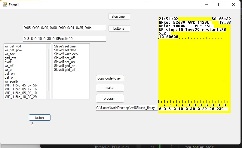
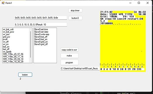
Softwareoberfläche zur UART-Kommunikation und Statusanzeige
1129W Grid: 108.0W PU: 15V WR stop:10 low:29 restart:30 5_2 10100000 0x05, 0x03, 0x00, 0x00, 0x01, 0x85, 0x8e button3 0, 3, 6, 0, 10, 30, 0, 0 Result: 10 wr_bat_volt Slave5 set time wr_bat_pow Slave5 set date wr_soc Slave5 write eep grid_pw Slave5 bat_off pvolt Slave5 bat_on wr_off Slave5 grid_on wr_on Slave5 grid_off bat_on bat_off WR_115to_45_57_56 WR_115to_05_17_16 WR_115to_05_09_10 WR_115to_10_30_29 copy code to avr make program C:\Users\karl\Desktop\uart_fleury testen 2 0 3 6 0 10 30 0 29 20 235
-
Thread
VDD durch Schottky-Diode von ICSP-VDD trennen - Trotzdem Spannungsanstieg
programmiere - das ist natürlich tödlich für alle auf 3,3V ausgelegten Bauteile. Es scheint als würde die BAT64-Diode nicht sperren? Woran kann das liegen? Durchgemessen habe ich die Diode und sie sperrt dann auch. Gruß, Tobias
der Nachteil von Schottky... da fliesst immer ein bischen Strom in die falsche Richtung. Bei der BAT64 können das schon 0.2mA werden (bei 85°C), ist aber eher im Bereich deutlich kleiner 2µA für "normale" Temperaturen und Spannungen. Wenn der Rest deiner Schaltung nun auf extremes Stromsparen getrimmt
-
Thread
ADC Eingang schützen, wie?
werde ich mal 2 Dioden in Reihenschatung von Masse gegen VCC probieren. Habe in den Beiträgen die BAT46 und die BAT85 gefunden aber diese sind ja nur für 100 bzw. 30V geeignet.
-
Thread
Drehspulmesswerk schützen
_ | | + / \ - | +---->|----( A )--------+ BAT43 \_/ Direkt seriell möchte ich ungern eine Diode setzen, weil bei kompletter Sperrung sonst eine sehr hohe Spannung an der Diode abfallen könnte (Spannungsumkehr nach Lichtbogenüberschlag
200mV (laut Multimeter). Immer 5 Dioden von jeder Art getestet (auf 10er gerundet) SB130 360-490uA BAT43 130-150uA 1N5819 300-380uA BAT85 210-240uA 10SQ045 500-600uA Das schlimme dabei ist jedoch, dass wenn ich der Strom erhöhe in den 100er mA Bereich, die Spannung auf 300mV bis gar über 500mV
-
Thread
Tiny85 wacht nicht auf
Tach, ich habe ein RFM12 am Tiny85 hängen und möchte nach Senden eines Pakets den Tiny schlafen schicken. Mit einem Mega128 getestet und funktioniert , wenn ich die sleeproutine durch einen delay ersetze funktionieren die Routinen auch
Flanke weil ich im Betrieb die fallende Flanke vom RFM12 auswerte. @Michael U. : hast du beim Tiny85 schon einmal das EEPROM beschrieben ? Gruß Oddel
-
Thread
symmetrischer Spannungsversorgung mit unsymmetrischem Zweig- was mache ich falsch?
sind bei 1mA recht ungenau, nach dem (unvollständigen) Diagramm in www.eworld.ru/store/smc/ds/bzx85.pdf hat eine BZX85C3V0 bei 1mA eine Spannung unter 1.8V und damit zu wenig für deinen A/D-Wandler. Nimm lieber einen 3V Spannungsregler wie LM2950-3, das spart auch noch den Vorwiderstand (aber nicht
bei 1mA recht ungenau, > nach dem (unvollständigen) Diagramm in > www.eworld.ru/store/smc/ds/bzx85.pdf > hat eine BZX85C3V0 bei 1mA eine Spannung unter 1.8V und damit zu wenig > für deinen A/D-Wandler. > Nimm lieber einen 3V Spannungsregler wie LM2950-3, das spart auch noch > den Vorwiderstand
-
Thread
Suche: OPV / Transistoren zum Basteln
alle 25 Volt (je 5x) Keramikkondensator: 1 nF, 10 nF, 100 nF (je 10x) Dioden: 1N4148, 1N4007, BAT43 oder BAT85 (je 10x) LEDs 5mm: rot, grün, gelb, blau, weiß (je 5x) Transistoren: 10x BC547, 10x BC557, 3x TIP41C Operationsverstärker (OPV oder OpAmp): 5x LM324 Universal-Timer-IC: 5x NE555 Spannungsregler
-
Thread
Mit Script USB Eintrag aus Registry löschen
Threadstarter vermutlich erwartet. http://msdn.microsoft.com/en-us/library/windows/hardware/ff546173%28v=vs.85%29.aspx
@christian irgendwas machst du falsch http://www.robvanderwoude.com/devcon.php RmHidDev.bat vielleicht hilfts!?
-
Thread
DAB+ Modul KeyStone 8650
Sieht gut aus, ich habe mir das auch nur vom Monkeyboard abgeguckt. Der Pullup an BAT_DET hat bei mir 1k, der am Reset 100k, sonst finde ich keine Unterschiede. Jörg
Danke Jörg für deine Hilfe. Wichtig ist, dass BAT_DET 1k bekommt, statt 10k. Es funktioniert jetzt.
-
Thread
# Jemand Erfahrung mit den neuen Rigol DHO 800er
comment like this: rem call "adb\05 make Backup And pull it - adb rm updateGEL, sh buildGEL, pull.bat" 3) Run the "run_DHO_Tools.bat" 4) Send the generated SCPI commands to the scope via the SCPI browser tab, opened by the script. Common command view: :SYSTem:OPTion:INSTall DHOX00-<option
MHz Bandbreite reicht das schon nichtmehr. Hallo, bei meinem DHO1074 ist die Bandbreite etwa 85 MHz. MfG egonotto
-
Thread
Nürnberg, Job? NT/ET
2445.50 2525.94 2601.03 E 8 2119.43 2456.23 2456.23 2552.76 2660.01 2727.58 E 9 2264.23 2509.85 2638.57 2981.79 3249.94 E 10 2563.48 2842.35 3056.87 3271.39 3678.97 E 11 2660.01 2949.62 3164.13 3485.90 3952.49 E 12 2756.55 3056.87 3485.90 3861.31 4343.98 E 13 3075.10 3410.82 3593.17
für E13 auch ausgestattet ist. Na sowas, ich war auch im ÖD da hat ein Kraftwerksmeister nach BAT IIb seine Gehalt bezogen und wurde in Entgeldstufe 15 dann eingruppiert! Das war aber auch ein Betrieb mit Betreibsrat, keine Behörde mit Personalrat! Merke also TvÖD ist Leistungsbezogen!
-
Thread
Wetterstation zeigt bei 1,17V "Bat" leer an
Wetterstation zeigt bei 1,17V Batteriespannung "Bat" leer an Das Gerät stellt seine Funktion bei 1,1V ein. Die Batterie ist dann ja nicht leer. Wie sauge ich alternativ aus dem Batterien noch Strom um die Wetterstration weiter zu betreiben? Joule
Gerd S. schrieb im Beitrag #4482188: > Wetterstation zeigt bei 1,17V Batteriespannung "Bat" leer an > > Das Gerät stellt seine Funktion bei 1,1V ein. > Die Batterie ist dann ja nicht leer. Schau dir mal eine Entladekurve einer beliebigen Batterie an. Die Batterie ist praktisch leer
-
Thread
Schottky - Brückengleichrichter?
BAT54S https://i.stack.imgur.com/1Z5So.png Ja dann schon! Gruss Chregu
Christian M. schrieb im Beitrag #5211189: > BAT54S Jup, bei Reihenschaltung schon. DANN gilt auch: Frank schrieb im Beitrag #5211163: > (nur gemischt geht nicht) ... :) Thema High-Power-Schottky als Brücke: Die einzigen mir bekannten
-
Thread
Wie Arduino Projekt ohne Arduino IDE benutzen?
für den Uno gebastelt und flashe damit sowohl Arduino code als auch direkte hex-Dateien auf ATtiny85. Hilft dir das weiter?
BOOTLOADER with AVRDUDE: Assumes C:\AVRDUDE directory with: ---------------------------------- A.BAT AVRDUDE.CONF AVRDUDE.EXE A.HEX ////////////////////////////////////////////////////////////////////////////////////////////////////////////////////// WORKS: (Inside A.BAT) c:\AVRDUDE\avrdude -
-
Thread
Lithium Polymer Akku aus Asus T101HA wiederverwenden
www.best-microcontroller-projects.com/tp4056.html Nutze einfach den Akku (rote und schwarze Kabel), verbinde sie mit dem Bat+ und Bat- Anschlüssen der Platine und schon kannst du Out+ und Out- Pins ein Gerät ran hängen. Ist also ganz einfach.
www.best-microcontroller-projects.com/tp4056.html > > Nutze einfach den Akku (rote und schwarze Kabel), verbinde sie mit dem > Bat+ und Bat- Anschlüssen der Platine und schon kannst du Out+ und Out- > Pins ein Gerät ran hängen. Ist also ganz einfach. Ist das das wovor dein Link warnt? "You should never use the TP4056 as
-
Thread
TL494 peak current protection mit 3 Transistoren
erreichen, bei der die Schaltung leicht in den eingeschalteten Zustand springt und auch wieder über die BAT85 zurückgesetzt werden kann. Im Schaltbild erkennt man, daß ich einen 10 kOhm und einen 100 kOhm-Widerstand hinzu gefügt habe. Diese beiden Widerstände gilt es anzupassen bei neuen Aufbauten oder bei
Q3 über ihren Reststrom bzw. ihre Sperrschichtkapazität ein. Ein µA reicht dort ggfs. schon. BAT81 würde ich vorschlagen. Ein Filter zwischen Shunt und Basis ist aber sicher nötig,..." mit freundlichem Gruß
-
Thread
uDMX unter Win 7 64 Bit installieren
:( Also neu aufgesetzt da ich den Bluescreen nicht mehr weg bekam. Wenn ich jetzt uDMXConfigure.bat ausführem möchte steht jetzt immer: Fehler in uDMX.dll. Folgender Eintag fehlt: ConfigureModal da. Habe auch die uDMX.dll in Windows\System32 kopiert. Hat jemand einen Tipp was sich noch machen
CRC32: 84727D6B MD5: EDDF2BA3FB050C8BDD1E63F71E734435 SHA-1: 9F884BAE65D751002DF2764D89EBE2EBA61DF85B ...und soll wohl nach c:\windows\system32\ kopiert werden. Die "uDMXConfigure.bat" kann man dann von x-beliebiger Stelle aufrufen und er müsste die .dll aus dem system32-Ordner laden (sofern im Aufruf-Ordner
-
Thread
uC verlustfrei an 230V
sind die eher weniger das Problem? Wenn ja, welche Diode würde sich dazu eignen? Habe hier ein paar BAT43, aber da wird der Spannungsabfall bei größeren Strömen schnell mal gleich oder höher dem von 1N4007ern. lg PoWl
die eher weniger das Problem? Wenn > ja, welche Diode würde sich dazu eignen? Habe hier ein paar BAT43, aber > da wird der Spannungsabfall bei größeren Strömen schnell mal gleich oder > höher dem von 1N4007ern. Die Dioden sind weniger das Problem, eher die Spule, da hier wohl die meisten Verluste
-
Thread
I2C (TWI) Sniffer mit AVR
sind die Bedenken von Ron Hille berechtigt (Auszug aus Datenblatt): > Speed Grade > – ATtiny25/45/85V: 0 - 4 MHz @ 1.8 - 5.5V, 0 - 10 MHz @ 2.7 - 5.5V > – ATtiny25/45/85: 0 - 10 MHz @ 2.7 - 5.5V, 0 - 20 MHz @ 4.5 - 5.5V Grüße Wolfgang
Hab ich nach dem wälzen des Datenblattes auch bemerkt. Hab mir schon Tiny85 bestellt. Bin mal gespannt :-) Danke schonmal
-
Thread
LED-Bargraph-Amperemeter für Motorrad
angesprochenen probleme umgangen. Es geht hier auch rein um die ladekapazität des generators in die bat.... oder eben aus der bat raus in den kreislauf. An besagter CX500 liegt der max ladestram nachm anlaßvorgang bei 1,5 A, um dann sofort auf unter 1A zu sinken. Während der fahrt dümpelt der zeiger
ihr einen bezahlbaren LED-treiberbaustein mit folgenden möglichkeiten: Temp-bereich -20 bis min. +85°C (125°C wäre genial) min. 10 ausgänge > led ausgansstrom hoch genug, daß kurzfristig (ca. 15 sec) alle 10 led gemeinsam versorgt werden können > dauerhaft 3-4 led > Bargraph eben SDI eingang LED-helligkeit
-
Thread
AVR128DA per USB flashen?
einfach Verbunden an UPDI angeschlossen, es braucht nur einen Widerstand (~1k) oder Schottky-Diode (BAT54 o.ä.) am TX-Ausgang. Das Tool selbst ist direkt von Microchip.
Beitrag #7191058: > Direkt über USB geht nicht. Natürlich geht das. Das geht sogar mit einem AtTiny85 ("Digispark"*). Voraussetzung ist hier ein Bootloader, der ein USB-CDC emuliert und darüber das Arduino-Bootloader-Protokoll abwickelt. Nur --und da hast Du recht-- auf einen "nackten" µC bekommt
-
Thread
Wie 12 Leitungen trennen (Potenzial unterschiedlich)
Verbindungen ausreichen. https://datasheets.maximintegrated.com/en/ds/MAX14756-MAX14758.pdf muss an +Bat(ca. 50V) und Masse angeschlossen werden und bleiben, zieht dann 500uA, und trennt dann die 11 Leitungen so dass weniger als 10nA fliessen. Macht man auch +Bat ab, fliesst Strom über die Eingangsschutzdioden
Wunder. Evtl. Kannst du ja von der anderen Seite die Platine anwärmen, normale Bauteile sind bis 85°C spezifiziert, sind also nicht gleich kaputt...
-
Thread
Wechselrichter Hoymiles HM-xxxx 2,4 GhZ Nordic Protokoll?
&& getSailPFc() == invConfigMO.getSailPFc()) && getSailPNum() == invConfigMO.getSailPNum()) && getBatSocAddr() == invConfigMO.getBatSocAddr()) && getBatSocFc() == invConfigMO.getBatSocFc()) && getBatSocNum() == invConfigMO.getBatSocNum()) && getBatPAddr() == invConfigMO.getBatPAddr()) && getBatPFc()
getSailPAddr()) * 37) + 66) * 53) + getSailPFc()) * 37) + 67) * 53) + getSailPNum()) * 37) + 68) * 53) + getBatSocAddr()) * 37) + 69) * 53) + getBatSocFc()) * 37) + 70) * 53) + getBatSocNum()) * 37) + 71) * 53) + getBatPAddr()) * 37) + 72) * 53) + getBatPFc()) * 37) + 73) * 53) + getBatPNum()) * 37) + 74) * 53
-
Thread
Verstärker 1-1500MHz 1Watt
hatte ich 10db zu wenig Signal. Wenn ich den SMHU um 3 KHz verstimmt hatte, war das Rauschen von -85dbV zu sehen. Das funktioniert auch mit dem 2MHz breiten 145MHz Filter. 145MHz -10 dbV ( wegen zu geringen Pegel des SMHU um 5MHz verstimmt. -85dbV Also hat der SMHU offenbar einen Rauschsockel von besser -85dbV bei 2MHz Filterbandbreite. Diesen ganzen Beobachtungen widerspricht aber die Tatschae das ich mit der HF Baugruppe unabhängig ob ich jetzt einen 2MHz Filter oder einen 2KHz Filter am Ausgang hängen