-
PDF
MB997.pdf
100nF STMicroelectronics D Title: STM32F4DISCOVERY ST-LINK/V2 (SWD only) NumberMB997 Rev:B.2(PCB.SCH) Date1/9/2012 Shee2 of 6 1 2 3 4 1 2 3 4 U4A4A P O P A 0 PA0A PIU4023 PIU4097PE0E P O P E 0 POPA10 PA1A
in „Mit STM32F4 einen Laser ansteuern“ · Mikrocontroller und Digitale Elektronik ·
-
Datei
STMPE811QTR.h
STMPE811QTR_H /* Includes ------------------------------------------------------------------*/ #include "stm32f4xx.h" #include "stm32f4xx_i2c.h" #include "stm32f4xx_dma.h" #include "stm32f4xx_rcc.h" #include "stm32f4xx_gpio.h" #include "stm32f4xx_syscfg.h" /** @addtogroup Utilities * @{ */ /** @addtogroup STM32F4_DISCOVERY * @{ */ /** @defgroup STM32F4_DISCOVERY_IOE * @{ */ /** @defgroup STM32F4_DISCOVERY_IOE_Exported_Types * @{ */ /** * @brief Touch Screen Information structure */ typedef struct { uint16
in „STM32F4 Touch Display Interrupt“ · Mikrocontroller und Digitale Elektronik ·
-
Datei
Blinky.txt
******************** /* Hinweis zum Clock fuer 8MHz Quarz, damit er auf 168MHz läuft (betrifft das stm32F4Discovery): in der system_stm32f4xx.c muss eingetragen sein: PLL_M = 8 in der stm32f4xx.h muss eingetragen sein: HSE_VALUE = 8000000 */ // Includes #include <stdio.h> #include <stdlib.h> #include "stm32f4xx.h" #include "stm32f4xx_gpio.h" #include "stm32f4xx_rcc.h" // Defines // LEDs #define LD_3_AUS GPIO_ResetBits(GPIOD,GPIO_Pin_13) // orange LED #define LD_3_EIN GPIO_SetBits(GPIOD,GPIO_Pin_13) static
in „Delay für STM32F4Discovery“ · Mikrocontroller und Digitale Elektronik ·
-
Datei
myfirst.s
.syntax unified .cpu cortex-m4 .thumb @ GPIO register map is similiar to STM32F4 chips. @ -> register boundary address pp. 65 in DM00031020.pdf .equ BIT0, 0x00000001 .equ BIT1, 0x00000002 .equ BIT2, 0x00000004 .equ BIT3, 0x00000008 .equ BIT4, 0x00000010 .equ BIT5, 0x00000020
in „Assemblerprogramm zur Ausgabe eines Zeichens auf UART3“ · Mikrocontroller und Digitale Elektronik ·
-
Datei
myfirst.s
.syntax unified .cpu cortex-m4 .thumb @ GPIO register map is similiar to STM32F4 chips. @ -> register boundary address pp. 65 in DM00031020.pdf .equ BIT0, 0x00000001 .equ BIT1, 0x00000002 .equ BIT2, 0x00000004 .equ BIT3, 0x00000008 .equ BIT4, 0x00000010 .equ BIT5, 0x00000020
in „Assemblerprogramm zur Ausgabe eines Zeichens auf UART3“ · Mikrocontroller und Digitale Elektronik ·
-
Datei
stm32f107.c
/** ****************************************************************************** * @file stm32f107.c * @author MCD Application Team * @version V1.0.0 * @date 11/20/2009 * @brief STM32F107 hardware configuration ****************************************************************************** *
in „STM32 System_Setup“ · Mikrocontroller und Digitale Elektronik ·
-
Datei
rs485.c
#include "stm32f10x.h" #include <stm32f10x_gpio.h> #include <stm32f10x_rcc.h> #include <typedef.h> #include <init.h> #include "stm32f10x_adc.h" #include "stm32f10x_dac.h" #include "stm32f10x_usart.h" #include "stm32f10x_dma.h
in „STM32 Tutorial“ · Mikrocontroller und Digitale Elektronik ·
-
Datei
main.c
configured, this is done through SystemInit() function which is called from startup file (startup_stm32f4xx.s) before to branch to application main. To reconfigure the default setting of SystemInit() function, refer to system_stm32f4xx.c file */ /* Initialize Leds mounted on STM32F4-Discovery board */ STM_EVAL_LEDInit(LED4); STM_EVAL_LEDInit(LED3); STM_EVAL_LEDInit(LED5); STM_EVAL_LEDInit(LED6); /* Turn on LED4 and LED5 */ STM_EVAL_LEDOn(LED4); STM_EVAL_LEDOn(LED5); /* Setup SysTick Timer for 1 msec
in „STM32F4 SysTick Fehler ?“ · Mikrocontroller und Digitale Elektronik ·
-
Datei
stm32f10x_it.c
****************************************************************************** * @file TIM/6Steps/stm32f10x_it.c * @author MCD Application Team * @version V3.5.0 * @date 08-April-2011 * @brief Main Interrupt Service Routines. * This file provides template for all exceptions handler and peripherals *
in „STM32F1 Brushless Motor Steuerung“ · Mikrocontroller und Digitale Elektronik ·
-
Datei
main.c
Quarz, damit er auf 168MHz l�uft (betrifft das stm32F4Discovery): in der system_stm32f4xx.c muss eingetragen sein: PLL_M = 8 in der stm32f4xx.h muss eingetragen sein: HSE_VALUE = 8000000 */ #include <stdio.h> #include <stdlib.h> #include <string.h> #include "stm32f4xx.h" #include "stm32f4xx_gpio.h" #include "stm32f4xx_rcc.h" #include "stm32f4xx_tim.h" #include "misc.h" #include "stm32f4xx_dma.h" // PORTA GPIO_Pin_3 wird zwischen 0 und 1 hin und her geschaltet
in „STM3F4 Bitstream erzeugen“ · Mikrocontroller und Digitale Elektronik ·
-
Datei
main.c
------------------- // File : main.c // Datum : 09.09.2014 // Version : 1.0 // Autor : AJ // CPU : STM32F4 // IDE : CooCox CoIDE 1.7.0 // Module : CMSIS_BOOT, M4_CMSIS_CORE // Hinweis : Diese zwei Files muessen auf 8MHz stehen // "cmsis_boot/stm32f4xx.h" // "cmsis_boot/system_stm32f4xx.c" //---------
in „STM32F4 DISCOVERY und SainSmart 3.2″ Display“ · Mikrocontroller und Digitale Elektronik ·
-
Datei
spi_caliper_stm32f4xx.c
/** @file spi_caliper_stm32f4xx.c * * Messschieber/Messuhr ueber den SPI auslesen * * $Date: 2019-08-23 21:38:31 +0200 (Fr, 23 Aug 2019) $ * $Revision: 860 $ * * @date 23.08.2019 Nicolas */ #include "spi_caliper.h" #include
in „STM32 "SPI"-Slave 24 Bit ohne Chip Select“ · Mikrocontroller und Digitale Elektronik ·
-
Datei
configx.h
endif #if USE_MMC //+++++++++++++++++++++ mmc +++++++++++++++++++++++++++++++++++ #include "C:\zuc\stm32_sd\ffconf.h" #include "C:\zuc\stm32_sd\integer.h" #include "C:\zuc\stm32_sd\diskio.h" #if zucSTM32 || zucLPC176x #include "C:\zuc\stm32_sd\mmc_32f1.c.h" //#include "C:\zuc\chan_sdx\ff_mmc_lowlevel.h" //VCT6 hw ok //VCT6 sw ok //avr sw ok //avr hw err #endif #if zucAVR // #include "C:\zuc\stm32_sd\mmc_32f1.c.h" //avr uspi ok #include "C:\zuc\chan_sdx\ff_mmc_lowlevel.h" //avr hw ok //avr sw ok //avr uspi err #endif #include "C:\zuc\stm32_sd\ff.h" #include "C:\zuc\stm32_sd\ff.c.h" FATFS FatFsx
in „Header Datei für Konfiguration erstellen“ · Mikrocontroller und Digitale Elektronik ·
-
Datei
stm32f4_discovery_audio_codec.c
========== User NOTES 1. How To use this driver: -------------------------- - This driver supports STM32F4xx devices on STM32F4-Discovery Kit. - Configure the options in file stm32f4_discovery_audio_codec.h in the section CONFIGURATION. Refer to the sections 2 and 3 to have more details on the possible
in „STM32F4 Discovery Audio DAC CS43L22“ · Mikrocontroller und Digitale Elektronik ·
-
Datei
STM32_Init.c
define _NVIC //#define _ADC //#define _GPIO //#define _EXTI #include "stm32f10x_lib.h" // STM32F10x Library Definitions #include "STM32_Reg.h" // missing bit definitions #define _SysTick //#include "..\_stdlibrary_V2_03_patch\inc\stm32f10x_systick.h" //#include "stm32f10x.h" //#include "stm32f10x_gpio.h" //#include "stm32f10x_nvic.h" // #include "stm32f10x_rcc.h" // #include "stm32f10x_tim.h" // #include "stm32f10x_exti.h" #endif //-------- <<< Use Configuration Wizard in Context Menu
in „Frage zu ST-Mikrocontrollern mit eMios“ · Mikrocontroller und Digitale Elektronik ·
-
PDF
STMxx-Discovery-Versaloon-How2.pdf
) 2: SWDIO/T_JTMS 3: GND 4: SWCLK/T_JTCK STM32VL ONBOARD Programmer When using the onboard JTAG to program the onboard target chip (the value-line chip) , you can't place the two CN3 jumpers as the manual says. The CN3
in „Use your STMxx-Discoveryboard as JTAG (SWD)“ · Mikrocontroller und Digitale Elektronik ·
-
PDF
TestArmTurtorialDeu.pdf
beliebt. Es sind mehrere Entwicklungsboards mit diesen Controllern verfügbar, zum Beispiel: Nucleo-F103, „/ users / hudakz / code / STM32F103C8T6_Hello / Blue Pill (suchen Sie nach „stm32f103c8t6“ auf AliExpress, Ebay oder Amazon), Quellhardware Olimexino-STM32, STM32-P103, / STM32-H103 / STM32-H103
in „ARM-Assembler-Tutorial“ · Mikrocontroller und Digitale Elektronik ·
-
Datei
sd_spi_stm32.c
OUT OF THE USE OF THIS SOFTWARE, EVEN IF ADVISED OF THE POSSIBILITY OF SUCH DAMAGE. */ //#include "stm32f10x.h" //#include "core_cm3.h" //#include "system_stm32f10x.h" #include "stm32f10x_conf.h" #include "defines.h" #include "main.h" //#include "stm32f10x.h" #include "ffconf.h" #include "diskio.h" /
in „STM32 - SPI Schnittstelle empfängt mal korrekt und dann wieder nicht“ · Mikrocontroller und Digitale Elektronik ·
-
Datei
code.txt
#include "stm32f10x.h" #include <stm32f10x_gpio.h> #include <stm32f10x_rcc.h> #include <typedef.h> #include <init.h> #include "stm32f10x_adc.h" #include "stm32f10x_dac.h" #include "stm32f10x_usart.h" #include "stm32f10x_dma.h
in „USART Remapping“ · Mikrocontroller und Digitale Elektronik ·
-
Datei
code.txt
#include "stm32f10x.h" #include <stm32f10x_gpio.h> #include <stm32f10x_rcc.h> #include <typedef.h> #include <init.h> #include "stm32f10x_adc.h" #include "stm32f10x_dac.h" #include "stm32f10x_usart.h" #include "stm32f10x_dma.h
in „USART Remapping“ · Mikrocontroller und Digitale Elektronik ·
-
Datei
myfirst.s
.syntax unified .cpu cortex-m4 .thumb .set LSE_fitted,0 @ GPIO register map is similiar to STM32F4 chips. @ -> register boundary address pp. 65 in DM00031020.pdf .equ BIT0, 0x00000001 .equ BIT1, 0x00000002 .equ BIT2, 0x00000004 .equ BIT3, 0x00000008 .equ BIT4, 0x00000010 .equ BIT5, 0x00000020
in „STM32CubeIDE - kann man dem gdb server einen Schalter mitgeben?“ · Mikrocontroller und Digitale Elektronik ·
-
Datei
myfirst168.s
.syntax unified .cpu cortex-m4 .thumb .set LSE_fitted,0 @ GPIO register map is similiar to STM32F4 chips. @ -> register boundary address pp. 65 in DM00031020.pdf .equ BIT0, 0x00000001 .equ BIT1, 0x00000002 .equ BIT2, 0x00000004 .equ BIT3, 0x00000008 .equ BIT4, 0x00000010 .equ BIT5, 0x00000020
in „STM32CubeIDE - kann man dem gdb server einen Schalter mitgeben?“ · Mikrocontroller und Digitale Elektronik ·
-
Datei
main.c
None * @retval None */ void GPIO_Configuration(void) { GPIO_InitTypeDef GPIO_InitStructure; #ifdef STM32F10X_CL /* GPIOE Configuration: Channel 1/1N, 2/2N, 3/3N as alternate function push-pull */ GPIO_InitStructure.GPIO_Pin = GPIO_Pin_9|GPIO_Pin_11|GPIO_Pin_13| GPIO_Pin_8|GPIO_Pin_10|GPIO_Pin_12; GPIO_InitStructure.GPIO_Mode
in „STM32 Six-step PWM signal generation using TIM1“ · Mikrocontroller und Digitale Elektronik ·
-
Datei
main.c
None * @retval None */ void GPIO_Configuration(void) { GPIO_InitTypeDef GPIO_InitStructure; #ifdef STM32F10X_CL /* GPIOE Configuration: Channel 1/1N, 2/2N, 3/3N as alternate function push-pull */ GPIO_InitStructure.GPIO_Pin = GPIO_Pin_9|GPIO_Pin_11|GPIO_Pin_13| GPIO_Pin_8|GPIO_Pin_10|GPIO_Pin_12; GPIO_InitStructure.GPIO_Mode
in „STM32F1 Brushless Motor Steuerung“ · Mikrocontroller und Digitale Elektronik ·
-
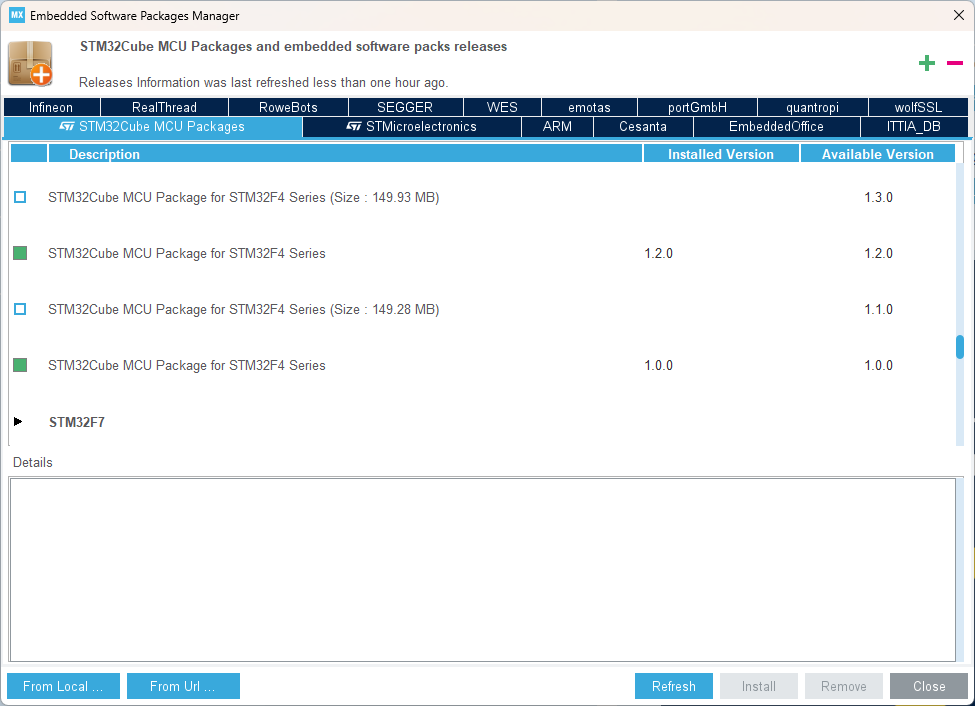
 Bild
Bild
MX Embedded Software Packages Manager Fenster
Version STM32Cube MCU Package for STM32F4 Series (Size : 149.93 MB) 1.3.0 STM32Cube MCU Package for STM32F4 Series 1.2.0 1.2.0 STM32Cube MCU Package for STM32F4 Series (Size : 149.28 MB) 1.1.0 STM32Cube MCU Package for STM32F4 Series 1.0.0 1.0.0 STM32F7 From Local ... From Url ... Refresh Install Remove Close
in „STM32CubeIDE: bekomme blinky läuft nicht“ · Mikrocontroller und Digitale Elektronik · · Screenshots
-
PDF
en.DM00108129.pdf
, delivered per series (such as STM32CubeF4 for STM32F4 series) – The STM32Cube HAL, an STM32 abstraction layer embedded software, ensuring maximized portability across STM32 portfolio – A consistent set of middleware components such
in „STM32F4 USB CLASS CDC (Virtueller Com Port)“ · Mikrocontroller und Digitale Elektronik ·
-
Datei
network_interface.h
----------- // Includes //-------------------------------------------------------------- #include "stm32f4xx.h" #include "stm32f4xx_gpio.h" #include "stm32f4xx_rcc.h" #include "stm32f4xx_syscfg.h" #include "stm32f4xx_exti.h" #include "misc.h" #include "stm32f4x7_eth_bsp.h" //#include "stm32f4x7_eth.h
in „Olimex STM32E407, FreeRTOS und lwip“ · Mikrocontroller und Digitale Elektronik ·
-
Datei
stm32_ub_spi1.h
//-------------------------------------------------------------- // File : stm32_ub_spi1.h //-------------------------------------------------------------- //-------------------------------------------------------------- #ifndef __STM32F4_UB_SPI1_H #define __STM32F4_UB_SPI1_H
in „STM32F429 - kein Takt am SPI“ · Mikrocontroller und Digitale Elektronik ·
-
PDF
textdisplayadapter_2.pdf
Quelldateien für folgende Mikrocontrollerfamilien zur Verfügung: Controllerfamilie Verzeichnis im Archiv STM8 ./stxlcd/stm8_pwm ./stxlcd/stm8_uart AVR ./stxlcd/avr_pwm ./stxlcd/avr_uart Padauk PFS154 ./stxlcd/pfs154/stx_lcd_transmit STM32F0 ./stxlcd/stm32f0 Auch hier gilt: Die Software ist unter Linux entstanden
in „"Intelligenter" Textdisplayadapter mit Padauk PFS154“ · Projekte & Code ·
-
Datei
code.txt
#include "stm32f10x.h" #include <stm32f10x_gpio.h> #include <stm32f10x_rcc.h> #include <typedef.h> #include <init.h> #include "stm32f10x_adc.h" #include "stm32f10x_dac.h" #include "stm32f10x_usart.h" #include "stm32f10x_dma.h
in „STM32 Tutorial“ · Mikrocontroller und Digitale Elektronik ·
-
Datei
code.c
#include "stm32f10x.h" #include <stm32f10x_gpio.h> #include <stm32f10x_rcc.h> #include <typedef.h> #include <init.h> #include "stm32f10x_adc.h" #include "stm32f10x_dac.h" #include "stm32f10x_usart.h" #include "stm32f10x_dma.h
in „STM32 Tutorial“ · Mikrocontroller und Digitale Elektronik ·
-
PDF
STM32F746-DISCO-OSCI.pdf
STM32F746G-DISCO-OSCI – recording into “Wave file” on SD-Card STM32F746G-DISCO-OSCI – only an “Estimation-Iron” (free translation from “Schätzeisen” ;-) or maybe a little bit more? The intention for this project: - Getting in touch with the STM32F7xx device family - Evaluation of STemWIN for GUI development So I bought my first “STM32F746G-DISCO”... ...and nothing is better for evaluation and whirl up potential problems more, than making a
in „STM32F746G-DISCO-OSCI mit WAV-Recording auf SD-Karte“ · Projekte & Code ·
-
Datei
codecIntegerSineWave.ino
// sine wave generator using the 16 bit codec of the // STM32F4 Discovery // // you need to copy the library from here // https://github.com/mubase/STM32F4-Arduino-core // to ... \arduino-1.6.9\hardware\Arduino_STM32 // after you installed the STM32 support
in „STM32F4 Discovery Arduino“ · Mikrocontroller und Digitale Elektronik ·
-
PDF
Atollic_Develop_Debug_BootloaderApps_ARMCortex.pdf
STM32F4-Discovery • STM32F4_Discovery_Bootloader_APP • STM32F4_Discovery_Bootloader_BL BL = Bootloader. APP = Application. Both must be downloaded. 2016-04-20 6 Memory map • Bootloader and application
in „GDB - ARM, Debug mit Offset“ · Mikrocontroller und Digitale Elektronik ·
-
Datei
adc_simple_stm32f4xx.c
stdio.h> #include <stdlib.h> #include "assert.h" #include "io.h" // fuer initGpioClock #if defined(STM32F4XX) // Hardwarespezifische Funktionen #include "stm32f4xx_adc.h" #include "stm32f4xx_gpio.h" #include "stm32f4xx_rcc.h" /* Hilfsfunktion: Kalibrierung vornehmen */ static void adc_calib(ADC_TypeDef *ADCx) { (void) ADCx; // Die STM32F4xx haben/brauchen dieses Feature nicht. } typedef struct { GPIO_TypeDef *Gpio; uint16_t ioPin; uint8_t channel; } Periph_t; #ifdef STM32F446ZE /* GPIO passend zum ADC-Kanal auswaehlen */ static Periph_t
in „Initialisierung ADC STM32F446 - gelöst“ · Mikrocontroller und Digitale Elektronik ·
-
PDF
UART_Test.pdf
Configuration Report 1. Description 1.1. Project Project Name UART_Test Board Name custom Generated with: STM32CubeMX 6.2.1 Date 08/02/2021 1.2. MCU MCU Series STM32F1 MCU Line STM32F103 MCU name STM32F103RBTx MCU Package LQFP64 MCU Pin number 64 1.3. Core(s) information Core(s) Arm Cortex-M3 Page 1 UART_Test
in „STM32F1 HAL UART Senden nicht“ · Mikrocontroller und Digitale Elektronik ·
-
Datei
code.txt
#include "stm32f10x.h" #include <stm32f10x_gpio.h> #include <stm32f10x_rcc.h> #include <typedef.h> #include <init.h> #include "stm32f10x_adc.h" #include "stm32f10x_dac.h" #include "stm32f10x_usart.h" #include "stm32f10x_dma.h
in „USART Remapping“ · Mikrocontroller und Digitale Elektronik ·
-
PDF
techb_GraficLCD_de_en.pdf
Controller from Displaytech with Sitronix ST7565R controller • Steckerleiste für den Anschluss an ein mySTM32 F4 • Male pin header to connect with a mySTM32 F4 Discovery PLUS Discovery PLUS • Buchsenleiste für den Anschluss weiterer Module • Female connector for other modules • Raster für flexible Anwendung
in „LCD Ansteuerung“ · Mikrocontroller und Digitale Elektronik ·
-
Datei
Scratch_MegaSample.c
#include "stm32f4xx.h" #include "system_stm32f4xx.h" #include "stm32f4xx_gpio.h" #include "stm32f4xx_rcc.h" #include "misc.h" #include "stm32f4xx_exti.h" #include "stm32f4xx_syscfg.h" #include "stm32f4xx_spi.h" #include "stm32f4xx_usart.h" #include "stm32f4xx_adc.h" #include "stm32f4xx_dma.h" #include "Scratch_MegaSample.h" void Init_USART2(){ // Enabling the Clock for the USART1 RCC_APB1PeriphClockCmd(RCC_APB1Periph_USART2
in „STM32F4 ADC/DMA Phänomene“ · Mikrocontroller und Digitale Elektronik ·
-
PDF
STM32H7-Disco_full.PDF
kHz IC00043 STM32H743IIT6 STM32H743IIT6 C1C8 U5D PI11PC0 GND PU04 PD0_SDRAM_D 22 PD0 PU04 PD1_SDRAM_D 33 50 V PD1 144 PD2_SDcard_CMD 2.2 pF PD2 P145 PD3_LTDC_ 7 PD3 PU04 NLP40 cad0etet PD4 PU04 PD4_SD r _ etect C PD5
in „STM32H7-Disco erster Test“ · Mikrocontroller und Digitale Elektronik ·
-
Datei
adc_dma.c
#include "string.h" #include "stm32f0xx_adc.h" #include "stm32f0xx_dma.h" #include "stm32f0xx_gpio.h" #include "stm32f0xx_rcc.h" #include "stm32f0xx_misc.h" #include "stm32f0xx_tim.h" volatile uint16_t ADCReadBuffer[] = { 0xAAAA, 0xAAAA, 0xAAAA }; volatile uint32_t Milliseconds = 0, Seconds = 0; uint16_t u16AnalogIn[3]; uint32_t u32Counter; void Init_ADC(void) { DMA_InitTypeDef DMA_InitStructure; GPIO_InitTypeDef GPIO_InitStructure; ADC_InitTypeDef ADC_InitStructure
in „ATM32F030 + ADC + DMA“ · Mikrocontroller und Digitale Elektronik ·
-
Datei
0001-Add_Frre_Text_Support_To_STM32.patch
--------- + */ +#ifndef FREETEXT_H +#define FREETEXT_H + +#include "eeprom-data.h" + +#if defined (STM32F10X) +# include "stm32f10x.h" +#elif defined (STM32F4XX) +# include "stm32f4xx.h" +#endif + +typedef struct +{ + char free_text[EEPROM_DATA_SIZE_FREE_TEXT+1]; +} FREETEXT_GLOBALS; + +extern FREETEXT_GLOBALS
-
Datei
graphik.h
ifndef GRAPHIK_H_INCLUDED #define GRAPHIK_H_INCLUDED // Special Libs #include "defines.h" #include "tm_stm32f4_ili9341.h" #include "tm_stm32f4_delay.h" #include "tm_stm32f4_rng.h" #include "tm_stm32f4_rtc.h" #include "tm_stm32f4_bmp180.h" #include "tm_stm32f4_general.h" #include "tm_stm32f4_disco.h" #include "tm_stm32f4_gpio.h" /* LCD settings */ #define ILI9341_WIDTH 240 #define ILI9341_HEIGHT 320 // Transformiert Koordinaten auf 0,0 bezogen auf linke, untere Ecke #define TransX(x) (x) #define TransY(y) (ILI9341
in „Organisation der Header und Includes“ · Mikrocontroller und Digitale Elektronik ·
-
Datei
main_stm32f429.c
#include "stm32f4xx.h" #include "stm32f4xx_conf.h" #include "stm32f4xx_rcc.h" #include "stm32f4xx_tim.h" #include "stm32f4xx_gpio.h" #define ARM_MATH_CM4 #include "arm_math.h" unsigned long ulCapturedTimerValue1
in „XMC4500 vs stm32f429.warum gibt es Unterschiede in der Berechnungsdauer?“ · Mikrocontroller und Digitale Elektronik ·
-
PDF
usr_scm_stm32com-a2-1.pdf
9 PC15 TDI 77 PA15 Q301 V V 32.7kHzQ/S STM32F107VCT6 1 / 3 3 STM32F107VCT6 PC15 A 3 3 0 3 6 6 + / 6 6 0 6 0 / 0 / 4 S 0 / 0 / 0 S 0 / R301 3 2 3 2 3 U 3 0 3 0 3 U 3 0 C 2 C 2 C302 C303 C 4 C 1 C 1 C 1 C 1 0R0/0603 A A A A 12p/0603
in „STM32-comStick USB-Bootloader“ · Mikrocontroller und Digitale Elektronik ·
-
Datei
main.c
configured, this is done through SystemInit() function which is called from startup file (startup_stm32f2xx.s) before to branch to application main. To reconfigure the default setting of SystemInit() function, refer to system_stm32f2xx.c file */ /* Initialize LEDs on STM322xG-EVAL board */ STM_EVAL_LEDInit
in „STM3220G-EVAL + Kamera OV2460“ · Mikrocontroller und Digitale Elektronik ·
-
Datei
stm32f103.cpp
//#include <assert.h> #include <Arduino.h> #include "stm32f103.h" #define DEBUG 0 /* Symbolic names for bit rate of CAN message */ // typedef enum {CAN_50KBPS, CAN_100KBPS, CAN_125KBPS, CAN_250KBPS, CAN_500KBPS, CAN_1000KBPS} BITRATE; /* Real speed for bit
in „Arduino Blue Pill & CAN mit SN65HVD230“ · Mikrocontroller und Digitale Elektronik ·
-
Datei
main.c
**************************** */ #include <stdio.h> #include <string.h> #include <math.h> #include "stm32f30x.h" #include "stm32f30x_rcc.h" #include "stm32f30x_misc.h" #include "stm32f30x_gpio.h" #include "stm32f30x_dma.h" #include "stm32f30x_usart.h" #include "stm32f30x_spi.h" #include "stm32f30x_i2c.h" #include "stm32f30x_syscfg.h" #include "stm32f30x_exti.h" #include "defines.h" #include "gpioctrl.h" #include "usart2dmactrl.h" #include "l3gd20ctrl.h" #include "lsm303ctrl.h" GPIO_InitTypeDef GPIO_InitStructure;
in „STM32F303 USART2 DMA1 funktioniert halblebig ?“ · Mikrocontroller und Digitale Elektronik ·
-
Datei
stm32f103.cpp
#include <assert.h> #include <Arduino.h> #include "stm32f103.h" #define DEBUG 0 /* Real speed for bit rate of CAN message */ uint32_t SPEED[6] = {50*1000, 100*1000, 125*1000, 250*1000, 500*1000, 1000*1000}; typedef struct { uint16_t baud_rate_prescaler;
in „Arduino Blue Pill CAN bibliothek“ · Mikrocontroller und Digitale Elektronik ·
-
Datei
stm32f103.cpp
-----------------------Testweise auskommentiert #include <assert.h> #include <Arduino.h> #include "stm32f103.h" #define DEBUG 0 typedef struct { uint32_t id; /* 29 bit identifier */ uint8_t data[8]; /* Data field */ uint8_t len; /* Length of data field in bytes */ uint8_t ch; /* Object channel(Not use
in „Arduino Blue Pill & CAN mit SN65HVD230“ · Mikrocontroller und Digitale Elektronik ·