-
Thread
CH32V006 und CH32V007 von WCH
zufriedenstellende Vielfalt an MCU's vorhanden, die sehr viele Anwendungsbereiche abdecken und dabei wirklich Low-Cost sind.
extensions can be flexibly applied to different scenarios of microcontroller design, such as small area low-power embedded scenarios, high performance application operating system scenarios, etc. * Support machine and user privileged modes * Programmable Fast Interrupt Controller (PFIC) * Multi-level hardware
-
Thread
[V] 8 Kanal Solid State Relais Karte mit Gehäuse
to 264V AC (50/60Hz). - Load current: 0.1 to 2 AMP. Input control signal voltage: - 0V - 0.5V Low stage (SSR is Off). - 0.5V - 2.5V (unknown state). - 2.5V - 20V High state (SSR is On). SSR Spec: Manufacturer: OMRON Part number: G3MB-202P, 5V version. Isolation: Phototriac. Zero cross:
Mike M. schrieb im Beitrag #8072605: > Input control signal voltage: > - 0V - 0.5V Low stage (SSR is Off). > - 0.5V - 2.5V (unknown state). > - 2.5V - 20V High state (SSR is On). Und bei 5V fließen 2mA, AFAIR.
-
Thread
Digikey teurer, Vivado unter Jahresabonnement, kostenlose Compiler von Microchip uvam
programmer with UART connection • PowerIO Shield - Extended power capabilities with six 3A high-side switches at up to 48V • Arduino headers - Compatible with a wide range of Arduino shields and accessories [/c] Unter https://mercedes-benz.github.io/ardep/samples/uds/README.html findet
including PicoBNC+ and some active probes — are scaled incorrectly. In some cases, readings register lower than the true value, so a potentially hazardous measurement can appear safe. If you installed the ARM version of PicoScope 7, upgrade to 7.2.24 Stable or 7.2.26 EA (Early Access) — or any later
-
Thread
Alte Eproms sichern, welches Gerät?
Meist liefert die höhere Spannung den richtigen Inhalt. Beim Beispiel im Anhang weicht der Verify high vom Verify nominal und Verify low ab. Da EPROMs der 27(C)xxx-Familie nach 0xFF löschen, ist das Image mit den meisten Nullen das richtige. 87(C)xxx löschen nach 0x00, da ist es umgekehrt.
-
 Bild
Bild
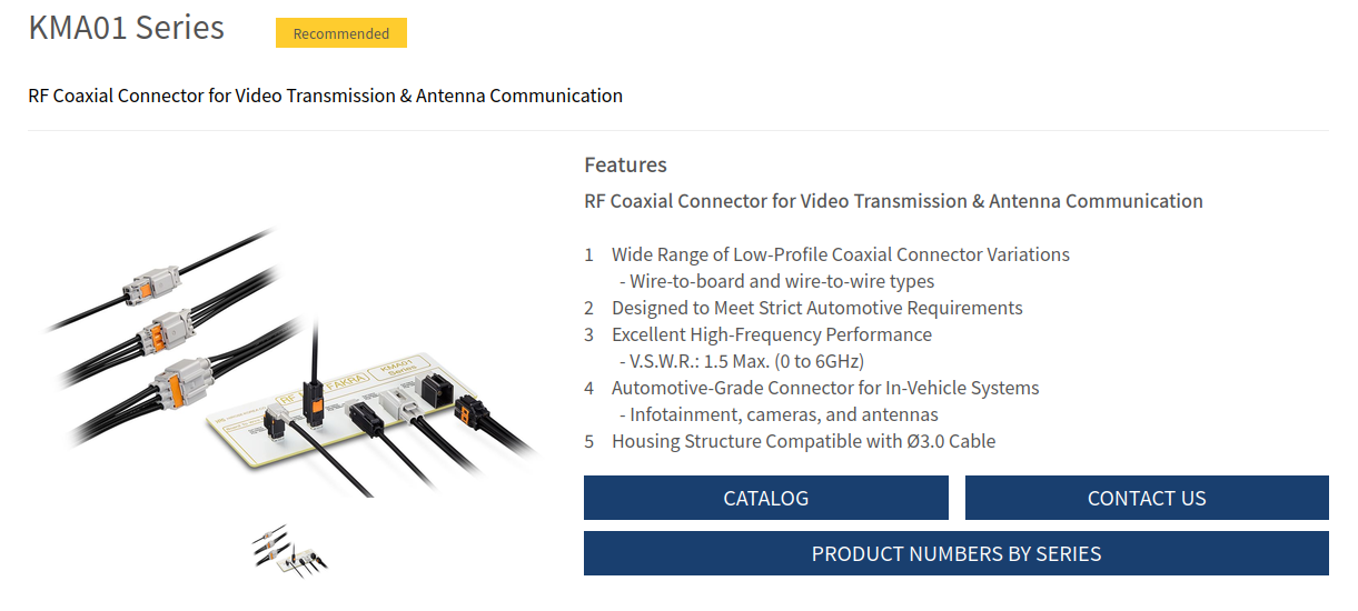
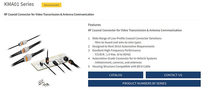
Produktseite für KMA01 RF Koaxialstecker
Communication Features RF Coaxial Connector for Video Transmission & Antenna Communication 1 Wide Range of Low-Profile Coaxial Connector Variations - Wire-to-board and wire-to-wire types 2 Designed to Meet Strict Automotive Requirements 3 Excellent High-Frequency Performance - V.S.W.R.: 1.5 Max. (0 to 6GHz)
-
Artikel
AVR-GCC-Tutorial
: Erst Low-Byte, dann High-Byte Schreibzugriff: Erst High-Byte, dann Low-Byte Des weiteren ist zu beachten, dass es für all diese 16-Bit-Register nur ein einziges temporäres Register gibt, so dass das Auftreten
ca. 0,2*Vcc) anliegt. Detaillierte Informationen darüber, ab welcher Spannung ein Eingang als 0 ("low") bzw. 1 ("high") erkannt wird, liefert die Tabelle DC Characteristics im Datenblatt des genutzten Controllers. + Logikpegel VCC [V] Low [V] High [V] 5 1,0 3,5 3,3 0,66 2,3 1,8 0,36 1,26 Die Abfrage
-
Thread
Phasenerkennung für Campingplatz mit Glimmlampe? Gesperrt
Schiffen ist eine solche Erkennung vorgeschrieben und wird auch genau so mit Glimmlampen (modern auch mit Low Power LEDs) gegen PE umgesetzt. Beispiel anbei
Und noch 'ne Schippe drauf: https://en.wikipedia.org/wiki/High-leg_delta "Wie kommen die auf 208 Volt?" ciao gustav
-
 Bild
Bild
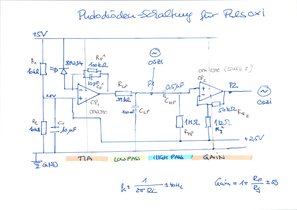
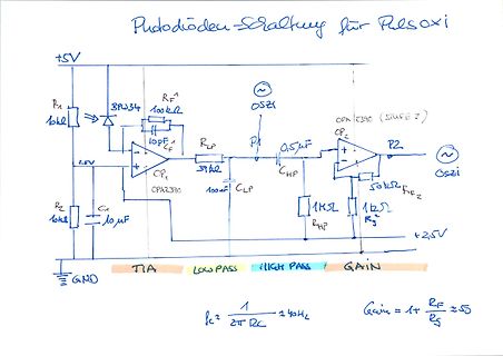
Handgezeichneter Schaltplan einer Photodiode-Schaltung für Pulsoxi
OPA2390 OP1 CF 10pF RLP 39k CLP 100uF CHP 0,5uF RP R1 10k R2 10k C1 10uF RG 1k RF2 50k +2,5V GND TIA LOW PASS HIGH PASS GAIN fc = 1/(2*pi*RC) = 40Hz Gain = 1 + RF/RG = 51
-
 Bild
Bild
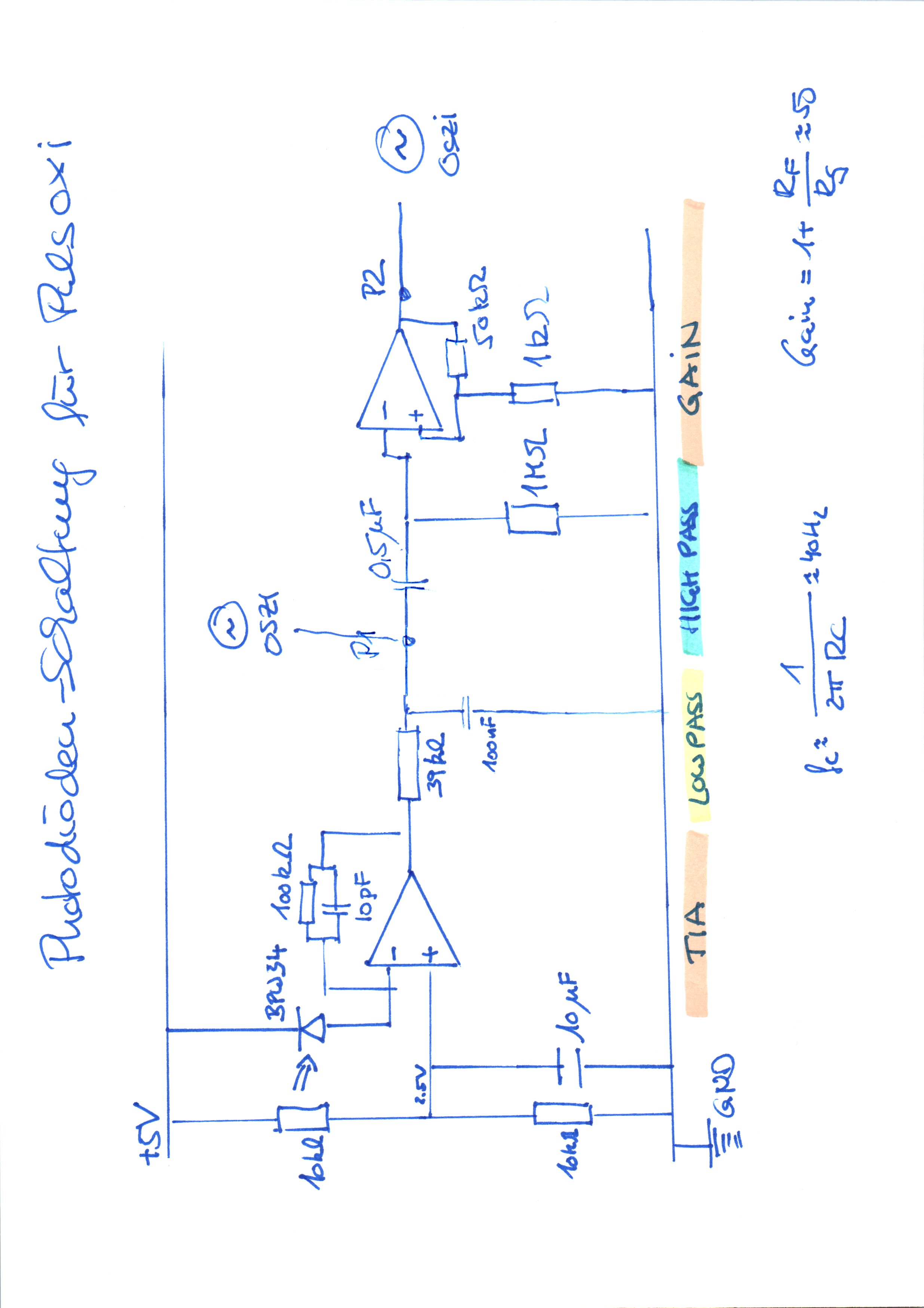
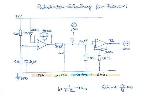
Handgezeichneter Schaltplan einer Photodiode-Schaltung für Pulsoxi
Photodiode-Schaltung für Pulsoxi +5V BPJ34 100k 10pF Oszi P1 0,5uF P2 Oszi 2.5V 39k 100uF 50k 1k 1k 10k 10uF TIA LOW PASS HIGH PASS GAIN GND fc = 1 / (2*pi*R*C) 140Hz Gain = 1 + RF/RS ≈ 55
-
 Bild
Bild
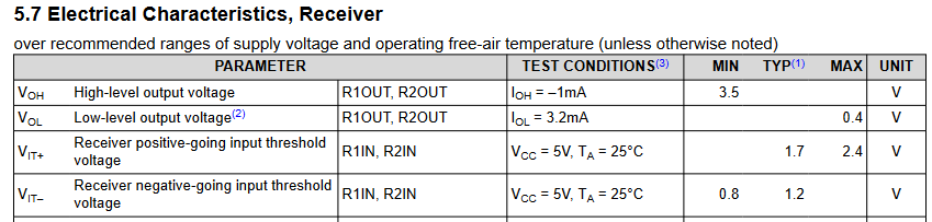
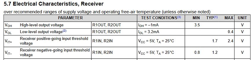
Tabelle der elektrischen Eigenschaften eines Receivers
free-air temperature (unless otherwise noted) PARAMETER TEST CONDITIONS(3) MIN TYP(1) MAX UNIT VOH High-level output voltage R1OUT, R2OUT IOH = -1mA 3.5 V VOL Low-level output voltage(2) R1OUT, R2OUT IOL = 3.2mA 0.4 V VIT+ Receiver positive-going input threshold voltage R1IN, R2IN VCC = 5V, TA = 25°C
-
Thread
Wo minimal board für ARM ( z.B. STM32U031K8U3) holen
www.seeedstudio.com/Wio-E5-LE-mini-Dev-Board-STM32WLE5JC-p-5764.html Die "LE" -Version ist jeweils die LowPower -Version die maximal 15dBm senden kann, ohne "LE" ist HighPower mit bis zu 22dBm. Letztere kann zwar auch heruntergeregelt werden auf z.B. 10dBm, verbraucht dann aber mehr als die LowPower-Version
Security-Koprozessor. Das STM32WL5MOC ist kompakter, hat dennoch mehr GPIOs und kann auch zwischen LowPower + HighPower umschalten bei entsprechender externer Beschaltung, ist aber auch schwieriger zu löten. Michael S. schrieb im Beitrag #8069092: > @erlkoenig sieh nicht schlecht aus, nur wolte ich
-
 Bild
Bild
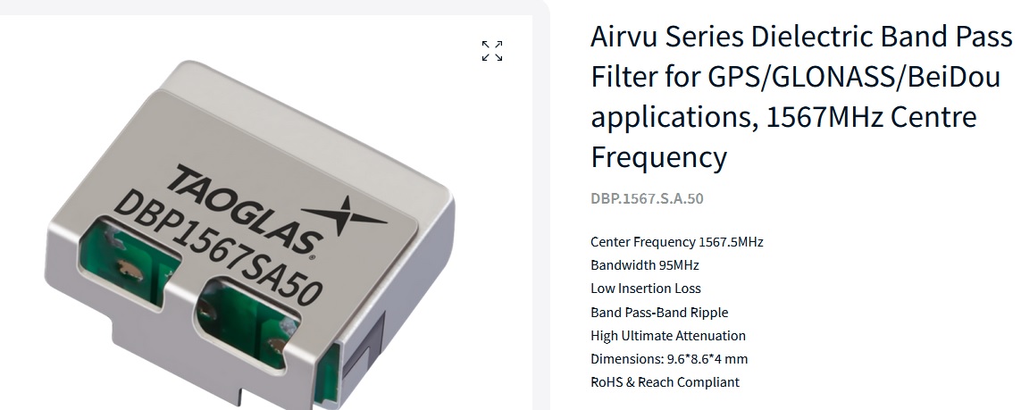
Taoglas Dielectric Band Pass Filter
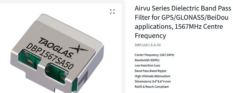
applications, 1567MHz Centre Frequency DBP.1567.S.A.50 Center Frequency 1567.5MHz Bandwidth 95MHz Low Insertion Loss Band Pass-Band Ripple High Ultimate Attenuation Dimensions: 9.6*8.6*4 mm RoHS & Reach Compliant TAOGLAS. DBP1567SA50
-
Thread
[V] Spectro-Color Platinen CV12864B LCD Display Ersatzteile
genauer angesehen: Der Analog Frontend für den Sensor ist ein AD7888 (12-Bit ADC), dazu zwei AD822 (Low Power FET-Input Op Amp). Die Versorgungsspannung über die Buchse beträgt vermutlich 6 Volt (das ist die Mindestspannung, wie viel maximal erlaubt ist habe ich nicht ausprobiert), der Stift ist dabei
beiden anderen 2-Pin Stecker ist unklar, am Größeren der beiden liegen die Ausgänge des TC4427 (DUAL HIGH-SPEED, POWER MOSFET DRIVERS). Die Stiftleiste am Batteriefach ist für BDM des HC12, Belegung siehe Bild. Eine Firmware ist bei meiner Platine nicht im Flash, allerdings befindet sich eine Firmware
-
Thread
Ultraschall Testsignale, Funktionsgenerator
lastRecordingDateEnabled": false, "dutyEnabled": true, "“passFiltersEnabled": true, "filterType": "high", "“lowerFilter": 60000, "higherFilter": 65535, "amplitudeThresholdingEnabled": true, "amplitudeThreshold": 0.1, — — "minimumAmplitudeThresholdDuration": 0 } This configuration is designed to record bats using a 250 kHz sample rate, recording using both a high-pass filter set at 60 kHz and amplitude threshold recording between 18:00 and 21:00. The LED is also disabled to prevent the device from being spotted while deployed. Also der Frequenzbereich reicht
-
Thread
SmartMeter mit MBus: simpler Pegelwandler gesucht
Deswegen sagte ich ja: theoretisch korrekt, praktisch irrelevant: zB MAX232: Über 2.4V wird high erkannt, unter 0.8V low. praktisch alle Datenblätter sagen, dass die Eingangsseite TTL-Kompatibel ist, selbst der uralte SN75189 (aus 1973). um peda zu zitieren: Man kann nur nicht die maximale
potentialfrei. Ich hab das Singal mit dem Oszi vermessen (siehe Anhang) Ruhepegel 26 Volt (High / Idle) Signal: 14 Volt, also ~12 Volt weniger Ein "Paket" dauert etwa 1700 ms Es kommt alle 10 Sekunden so ein Paket. Die kürzesten Pulse sind ungefähr 0,4 ms breit => deutet sehr klar auf
-
Thread
Arduino Uno Q-Preiserhöhung, Mikrocontroller mit Klasse D-Verstärker, OnSemi X Synaptics uvam
driver (LVPECL, LVDS or HCSL) or as a pair of single-ended CMOS outputs, the DSA504RT delivers ultra-low jitter performance as low as 200 femtoseconds (12kHz–20MHz) and is compliant with PCIe® Gen 1-7 standards. The DSA504RT, offered in QFN28 and CQFP32 packages, serves as a companion device for complex
Compared with conventional MnZn and NiZn ferrite cores, the nanocrystalline cores have significantly higher low-frequency impedance and broadband impedance behavior. WE-NCC is available for cable diameters from 3.7 to 21.1 mm. The initial permeability ranges from 30,000 to 90,000. Magnetic flux density reaches
-
Thread
Interner RC Oszillator von STM32C5 überraschend gut
Datenblatt verlinken https://www.st.com/resource/en/datasheet/stm32c531cc.pdf Kapitel 5.3.9.1 High-speed internal HSI144 oscillator
> Das ist nun einmal der Preis für die höhere Güte. Aber ist trotzdem kacke weil das bei LowPower extrem nervt. Kann dann zielfuehrend sein den internen RC zu nutzen und den nur gelegentlich mit einem externen Quarz zu kalibrieren. Ausserdem sind Quarze auch manchmal doch wenn du starke Vibrationen
-
Thread
Impulsausgabe mit Dreh-Inkrementalgeber
IC2B, IC2C und IC2D liefert am Ausgang (abgesehen von Spikes beim Umschalten der Eingänge) immer low. Damit sind die Ausgänge von IC3A und IC3B und schließlich auch die Ausgänge LEFT und RIGHT immer high. Diese Funktionalität kann man auch mit 0 statt 3 ICs erreichen ;-)
IC2B, IC2C und IC2D liefert am Ausgang (abgesehen > von Spikes beim Umschalten der Eingänge) immer low. > Ausgänge von IC3A und IC3B und schließlich auch die Ausgänge LEFT und > RIGHT immer high. Diese Funktionalität kann man auch mit 0 statt 3 ICs > erreichen ;-) OK, ich hab IC2C falsch verdrahtet
-
Thread
KickPi K7 / Orange Pi Zero – Prozessrechner ganz groß und ganz klein
// 4. Clean and fast toggle loop while (1) { gpiod_line_set_value(line, 1); // HIGH gpiod_line_set_value(line, 0); // LOW } // 5. Safe release if the loop ever breaks gpiod_line_release(line); gpiod_chip_close(chip); return 0; } [/c] ### Preisanalyse
-
 Bild
Bild
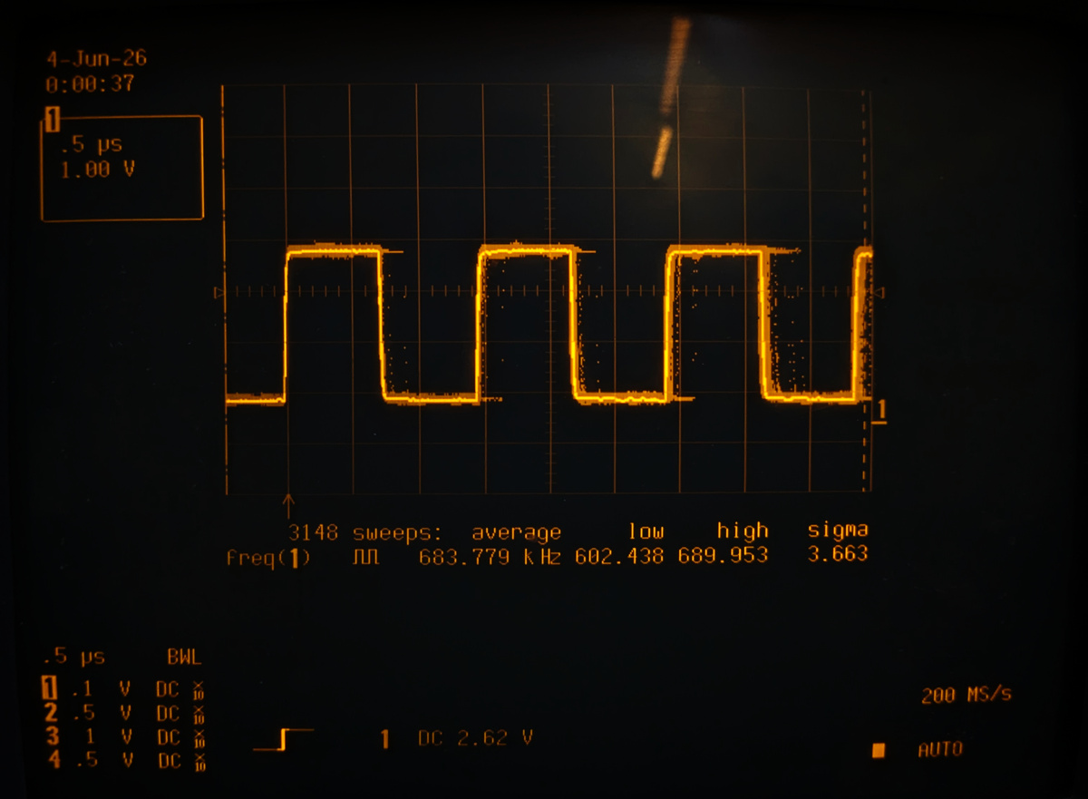
Oszilloskop-Messung eines Rechtecksignals
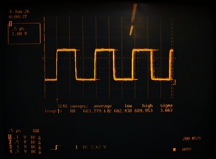
4-Jun-26 0:00:37 .5 µs 1.00 V 3148 sweeps: average low high sigma Freq(1) π 683.779 kHz 602.438 689.953 3.663 .5 µs BWL .1 V DC 2.5 V DC 3 1 V DC 4 .5 V DC 1 DC 2.62 V 200 MS/s AUTO
-
 Bild
Bild
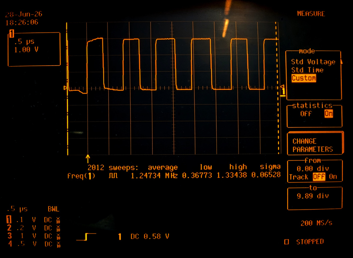
Oszilloskop-Messung eines Rechtecksignals
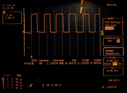
Std Time Custom statistics OFF On CHANGE PARAMETERS from 0.00 div to 9.89 div 2012 sweeps: average low high sigma Freq(1) 1.24734 MHz 0.36773 1.33438 0.06528 .5 µs BWL .1 V DC .2 V DC 3 1 V DC 4 .5 V DC 1 DC 0.58 V 200 MS/s STOPPED
-
 Bild
Bild
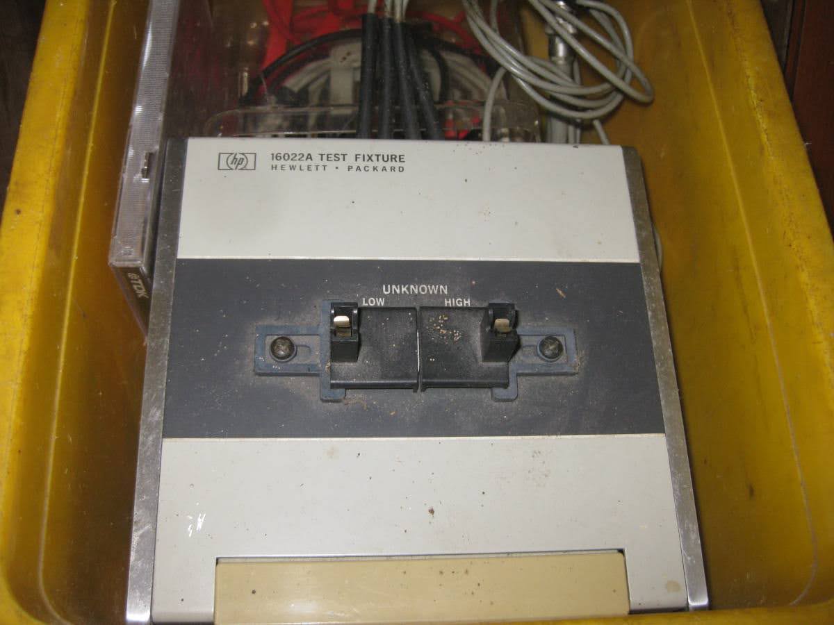
HP 16022A Test Fixture mit Schaltern
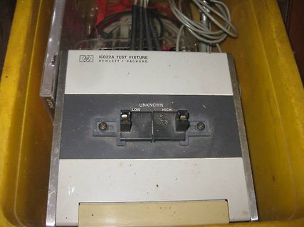
(hp) 16022A TEST FIXTURE HEWLETT - PACKARD UNKNOWN LOW HIGH
-
 Bild
Bild
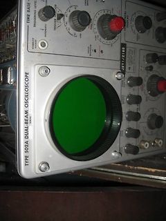
Analoges Oszilloskop mit grünem Bildschirm
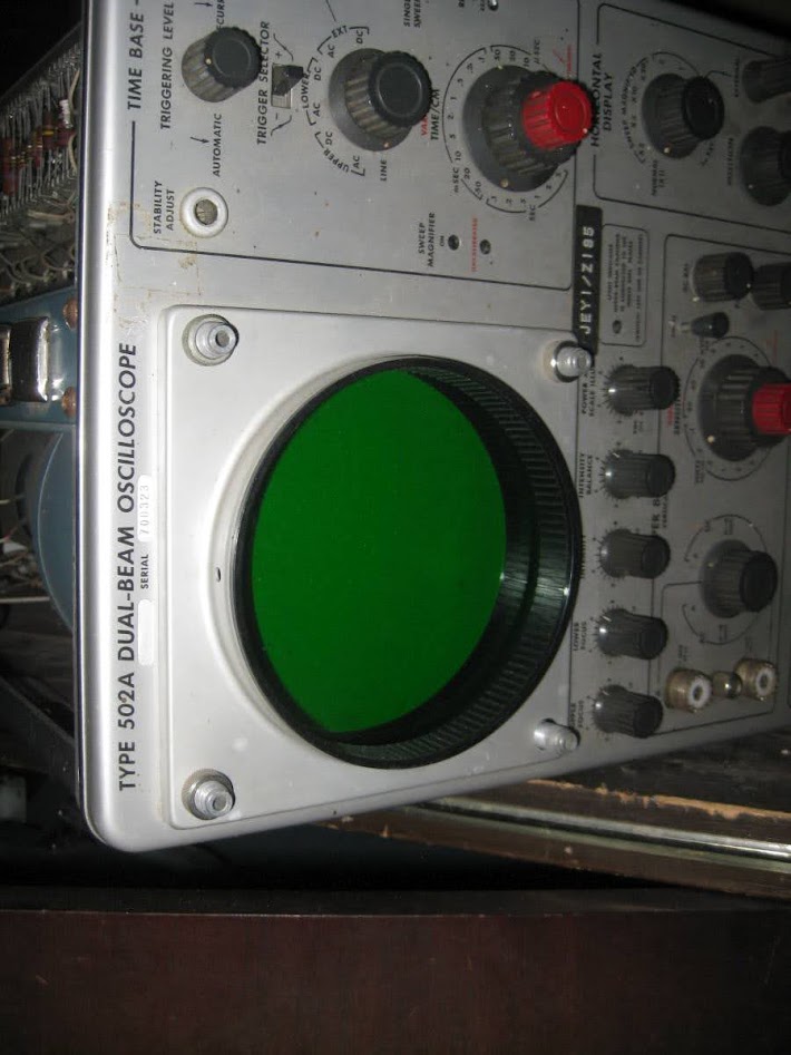
TIME BASE, TRIGGERING LEVEL, TRIGGER SELECTOR, LOW, HIGH, AUTOMATIC, STABILITY ADJUST, UP, DOWN, LINE, SWEEP MAGNITUDE, HORIZONTAL DISPLAY, JEY/Z185, TYPE 502A DUAL-BEAM OSCILLOSCOPE, SERIAL 708323, INTENSITY, BALANCE, VOLTS/DIV, TIME/DIV
-
Thread
Funktechnisches, neuer OrangePi, SigVSA und mehr
My and Google Find Hub networks, both crowdsourced location-finding ecosystems that use Bluetooth Low Energy (LE) and nearby smartphones to securely detect and report the location of tagged devices without GPS. . . . The nRF54L15 Tag supports rapid prototyping of Matter-enabled smart home products
measurements and provides high common-mode rejection for improved measurement accuracy. --- via https://www.siglenteu.com/news-article/siglent-launches-8-ghz-active-differential-probe-for-high-speed-and-rf-applications/ [/c]
-
 Bild
Bild
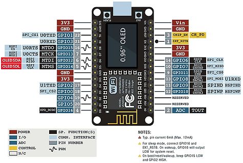
Pinbelegung eines ESP8266 Moduls mit OLED Display
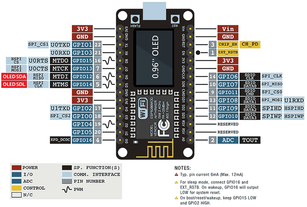
current 6mA (Max. 12mA) For sleep mode, connect GPIO16 and EXT_RST. On wakeup, GPIO16 will output LOW for system reset. On boot/reset/wakeup, keep GPIO15 LOW and GPIO2 HIGH.
-
Thread
Klimaanlage steuern in Abhängigkeit von PV-Leistung
Gesamtlänge austesten. Anschließend die Zeitdifferenzen ausdrucken und nach Startbitlänge, Pausen, High/Low-bits suchen. Dann mit bitwrite abspeichern. Zuletzt durch Änderungen der Temperatur die Bitpositionen suchen. Meist ist das binär codiert also 1, 2, 4, 8. Steht alles in meinem Code. Bei der Checksumme
-
 Bild
Bild
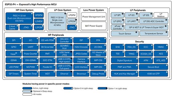
Blockschaltbild der ESP32-P4 Architektur
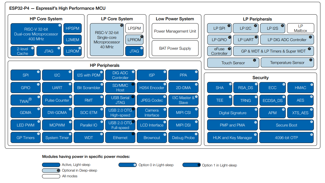
ESP32-P4 – Espressif's High Performance MCU HP Core System: RISC-V 32-bit Dual-core Microprocessor 400 MHz, HPSPM, L2MEM, JTAG, L2ROM LP Core System: RISC-V 32-bit Single-core Microprocessor 40 MHz, LPSPM, LPROM, JTAG Low Power
-
Thread
Suche SOC mit Funk und CAN
Edit: Lt. Datenblatt 32kb low-power SRAM und The main difference between ULP FSM and ULP RISC-V is that the latter can be programmed in C using standard GNU tools. The ULP RISC-V coprocessor can access the RTC_SLOW_MEM memory
Kannst auch auf den ESP32-P4 gehen, der ist bereits schon länger auf dem Markt. Ebenfalls mit RISC-V (Low Power 40MHz und High Power Dual Core 400 MHz, 32kB LP SRAM). Für CAN (im Bild TWAI) musst Du allerdings - genau wie für Funk - den großen Prozessor anwerfen. Wenn Die Funktionalitäten und Takt beschränkt
-
Thread
Seltsames Verhalten einer HD
externe Kopfpositionierung. Jegliche vom Benutzer ausführbare Formatierung, auch 04 FORMAT UNIT ("low-level Formatieren"), fasst die Servodaten und die Adressfelder nicht an, sondern initialisiert nur die Datenfelder.
nutzlos und die Karte besser unter einem Tischbein aufgehoben. Und ich rede jetzt nicht von special high endurance oder so.
-
 Bild
Bild
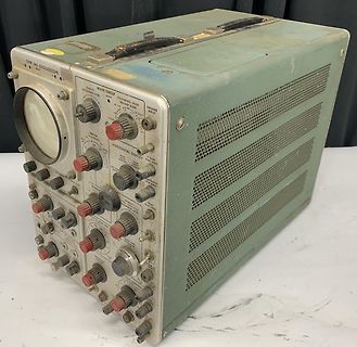
Altes analoges Oszilloskop
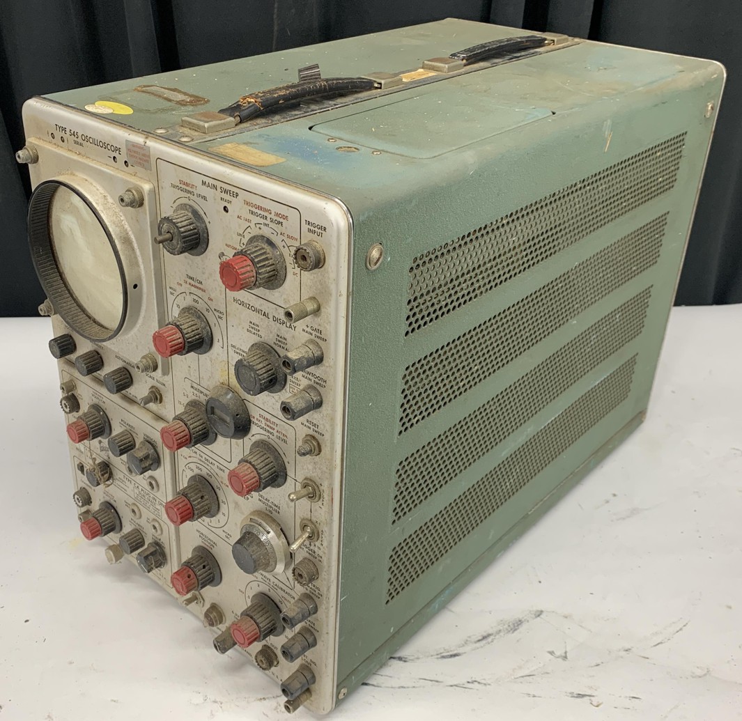
TYPE 545 OSCILLOSCOPE MAIN SWEEP STABILITY HIGHS/LOW LEVEL TRIGGERING MODE AC/DC TRIGGER SLOPE AC/DC TRIGGER INPUT HORIZONTAL DISPLAY TIME/DIV MAIN SWEEP VOLTS/DIV AC/DC OUTPUT INPUT CALIBRATION
-
Thread
PiPico zu langsame Flanken SPI-CLK
sich aus einem > kobstanten Strom ergibt. Ah ja, klar, der µC hat einen Konstantstromausgang. High ist 20 mA, Low ist 4 mA. Irgendwas mit Prozessor, also Signale aus der Prozesstechnik. Man kann hier wirklich unendlich viel lernen.
es so: > "The resolution enhancement feature is a flat moving-average filter. > This acts as a low-pass filter with good step response characteristics > and a very slow roll-off from the pass band to the stop band." Die hätten Politiker werden sollen. Mit vielen Worten bloß nix konkretes sagen