2. COB with Flex Flex with metallizations up Flex with metallizations down Figure 3. Flex Output Side Flex Output (FingerChip Connector Side) Metallizations Up 3 1 2 Note: 1. Flex is not provided by ATMEL. ® 4 AT77C102B FingerChip 5364A–BIOM–11/03 ® AT77C102B FingerChip Description The AT77C102B is
druckelalastischemerpackackungsmaterial auf alen Seiten verpacken. Zur Vermeiduidungiteret reräden m a G erät sid Statiksichere Verpacckungsmaterialien zu verwendenen. HP empfiehlt, alle Sendunngenzu versichernr . Beschreireibung d es 225-MHz-Unive-salziversalzählers U iversalzähler H 5 3131A und H 5 3132A könnnen
Signal type Transfer speed direction 106 kBd 212 kBd 424 kBd 848 kBd Reader to card (send reader side 100 % ASK 100 % ASK 100 % ASK 100 % ASK data from the modulation MFRC522 to a card) bit encoding modified Miller modified Miller modified Miller modified Miller encoding encoding encoding encoding bit length 128 (13.56 s) 64 (13.56 s) 32 (13.56 s) 16 (13.56 s) Card to reader card side subcarrier load subcarrier load subcarrier load subcarrier load (MFRC522 receives modulation modulation modulation modulation modulation data from a card) subcarrier 13.56 MHz / 16 13.56 MHz / 16 13.56
Volker S. schrieb im Beitrag #8000526: > Das beim Q1 ist eine Low-Side-Schaltung mit einem NPN, > weil ich ja den GND mit dem TFT-Display teile. Ich glaub der ist > korrekt? Zeichnung sagt "schaltet 3,3V". Dann ist der Transistor falschrum. Volker S. schrieb im
Volker S. schrieb im Beitrag #8000526: > Das beim Q1 ist eine Low-Side-Schaltung mit einem NPN, > weil ich ja den GND mit dem TFT-Display teile. Das ist nun überhaupt nicht zu erkennen. Gezeichnet ist kein NPN BJT. Der Q1 im Schaltplan ist ein P-Kanal MOSFET in der
FreeCAD/FreeCAD/issues/11017 und hier: https://forum.freecad.org/viewtopic.php?style=2&t=62084&sid=1c27fa5e06cf9aa6ce583aa4f62b5697&start=10 dokumentiert. Und so ist es halt nach meiner Erfahrung immer in FreeCAD. Es gibt (wie in jedem CAD Programm) 10 Wege zum Ziel. Alle Wege sind in FreeCAD
addDataPoint(data) { const time = new Date().toLocaleTimeString(); // Add new points to END (right side scrolling) chartData.times.push(time); chartData.esp32.push(parseFloat(data.internal) || 0); chartData.ds18.push(parseFloat(data.ds18b20) || 0); chartData.scd_t.push(parseFloat(data.scd_temp) || 0); chartData.bme_t.push(parseFloat(data.bme_t) || 0); // Limit to MAX_POINTS (remove from LEFT side) if (chartData.esp32.length > MAX_POINTS) { chartData.times.shift(); chartData.esp32.shift(); chartData.ds18.shift(); chartData.scd_t.shift(); chartData.bme_t.shift(); } drawChart(); } function update
oscillation and hardware reset • Shift change of segment and common drivers • COM positioned on both sides in one chip for COG Type Name Types External Dimensions HCD667A66RBP Au-bumped chip straight bump HCD667B66RBP Au-bumped chip laced bump Difference between HCD667x66R and HCD667x66 Table 1 Difference
bei Seeed öfter) Warum spekulieren? "Support for 3.7V LiPo batteries via two pads on the back side of the board; SGM40567 charging chip" https://www.cnx-software.com/2026/01/16/xiao-esp32-c5-a-tiny-usb-c-iot-board-with-dual-band-wifi-6-bluetooth-5-0-le-zigbee-and-thread-connectivity/
heads fifty percent of the time?” “I guess that’s because the coin weighs about the same on both sides, so there’s a fifty-fifty chance it will land on one side versus the other.” I tried to avoid sounding conde- scending. I wasn’t sure I succeeded. “You haven’t answered why. You simply listed some
für einen Kunden SSR aus dem Automotive Bereich (12V) ansteuern. Das SSR hat aber nur einen High Side Steuereingang. Wenn ich die PP der Beckhoff Klemme anschließe und mit dem Scope dran gehe, ist das PWM Signal weg und ich messe eine mit Störungen versehene Gleichspannung. Leider bin ich nicht
Widerstand dazwischen hängst? Was hat das SSR für eine Eingangsstufe, d.h. was genau meinst du mit "High Side Steuereingang"?
/ wave or with any other component must be assured. Soldering must be done from the opposite PCB side to where the capacitor body is placed. • Follow the specified heating and curing instructions given by supplier of the used adhesive or coating material. Avoid excessive pressure or heat on the capacitor
235-6847 International11-800-737-3360 Canada Solid State Sensors CS Series Linear Current Sensors SIDE MOUNT WITH 9SS SENSOR, SOURCE OUTPUT Sensitivity Sensed mV&N* Mtg. Supply Supply Current Offset At 12 VDC Offset Response Catalog Dim. Volt. Current (Amps Volt. Shift Time Listing Fig. (Volts DC) (mA
100BASE-TX 100BASE-FX and including the Physical Coding Sublayer (PCS), 10BASE-T operations. On the media side, it provides Physical Medium Attachment (PMA), Twisted Pair a direct interface either to Unshielded Twisted Pair Physical Medium Dependent Sublayer (TP-PMD), Category 5 Cable (UTP5) for 100BASE-TX Fast
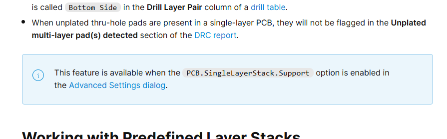
is called Bottom Side in the Drill Layer Pair column of a drill table.
When unplated thru-hole pads are present in a single-layer PCB, they will not be flagged in the Unplated multi-layer pad(s) detected section of the DRC
Control The DM8603 supports IEEE standard 802.3x flow control frames on both transmit and receive sides. On the receive side, The DM8603 will defer transmitting next normal frames, if it receives a pause frame from link partner. On the transmit side, The DM8603 issues pause frame with maximum pause time
register 52h. The DM8203 supports IEEE standard 802.3x flow control frames on both transmit and receive sides. On the receive side, The DM8203 will defer 9.2.3 Packet Forwarding transmitting next normal frames, if it receives a pause The DM8203 forwards the incoming packet frame from link partner. according to following decision: On the transmit side, The DM8203 issues pause (1). If DA is Multicast/Broadcast, the packet is frame with maximum pause time when internal forwarded to all ports, except to the port on which the resources such as received
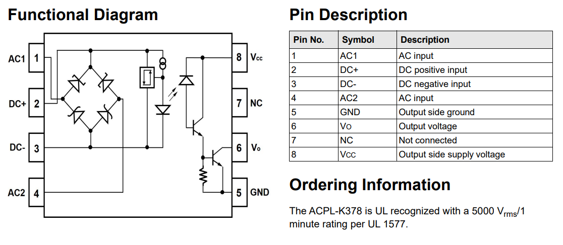
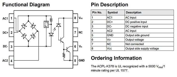
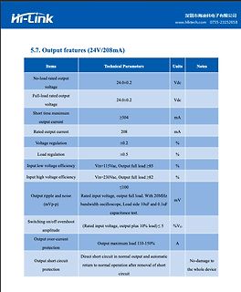
Description
1 AC1 AC input
2 DC+ DC positive input
3 DC- DC negative input
4 AC2 AC input
5 GND Output side ground
6 Vo Output voltage
7 NC Not connected
8 Vcc Output side supply voltage
Ordering Information
The ACPL-K378 is UL recognized with a 5000 Vrms/1 minute rating per UL 1577.
Top View Bottom View Detail "A" -H- 2.00 ±0.20 2.70 Max C 7° Seating Plane 0.80 0.25/0.50 0° 0.10 Side View 0°-7° 0.48 0.40 0.93 1.53 Package Outline 5° 0.88 +0.05/-0.15 1.6 Ref Detail "A" 0.25/0.40 Lead width with plating Lead thickness0.152 ±0.08 0.144/0.21Lead thickness with plating without plating
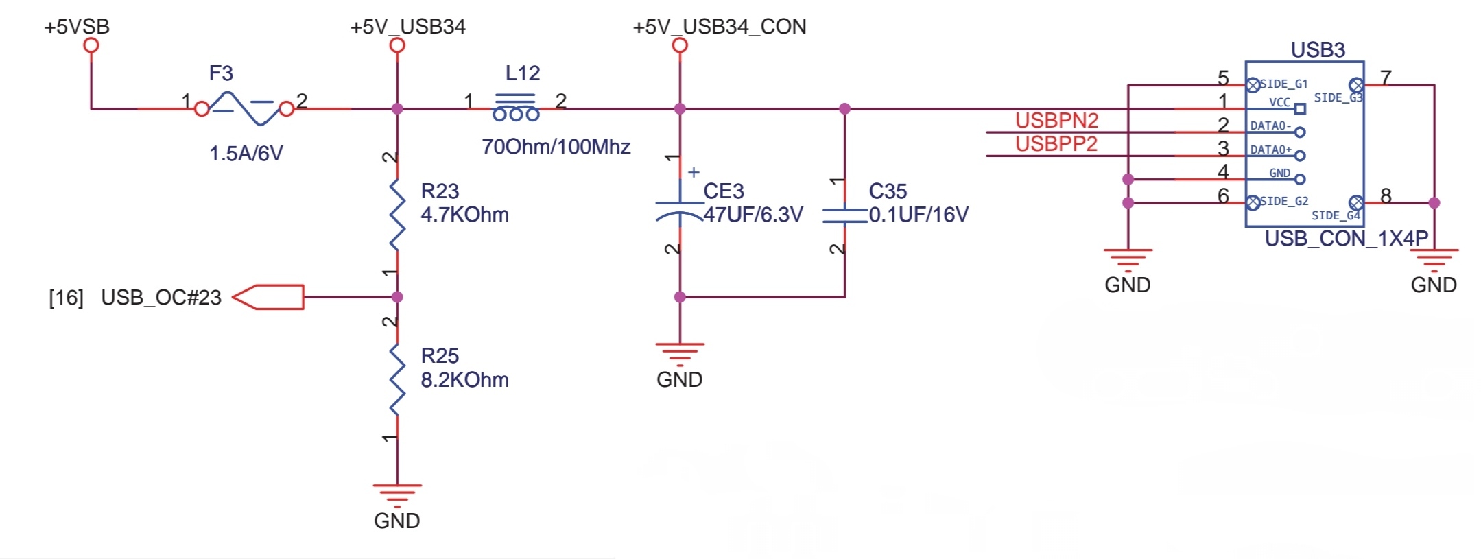
of the type and direction of the transistor: The welding direction of the LED: There is an aligned side that is the same with the PCB sign. Please note that the welding time of the LED should not be kept too long in case that the LED could be damaged. The electrode of the electrolytic capacitor should be aligned with the PCB side with white line. After all the welding jobs have been done, please connect the electric power instead of connecting Atmega328 and LCD(9V battery or external 5.5-12V DC power), and measuring the voltage
±1.270 7.949±1.270 (16.520) (90.600) BASE (14.000) 2X M3 X 0.5-6H 2X (3.000) MOUNTING HOLES: BOTH SIDES 7.000 0.200 MIN 3MM FULL THD BOTH SIDES 3.505+.075-.3X90 (90.600) (4.070) BASE (14.000) (61.720) 4X M3 X 0.5-6H MIN 23.505+.075-.3X90 Seagate BarraCuda Product Manual, Rev. A 19 Figure5 MountingDimensions
die GND für ein SIM-800l Modul. Passt eh nicht. IRLML6244 is ein p-MOSFET. Aber das Modul low-side zu schalten ist eh keine gute Idee.
schrieb im Beitrag #7987297: > Idee: N-Fet in der Plusleitung, Oder eben p-MOSFET. Für high-side gäbs ja noch was in THT: G040P02T von Goford. Und ein paar hat LCSC noch auf Lager.
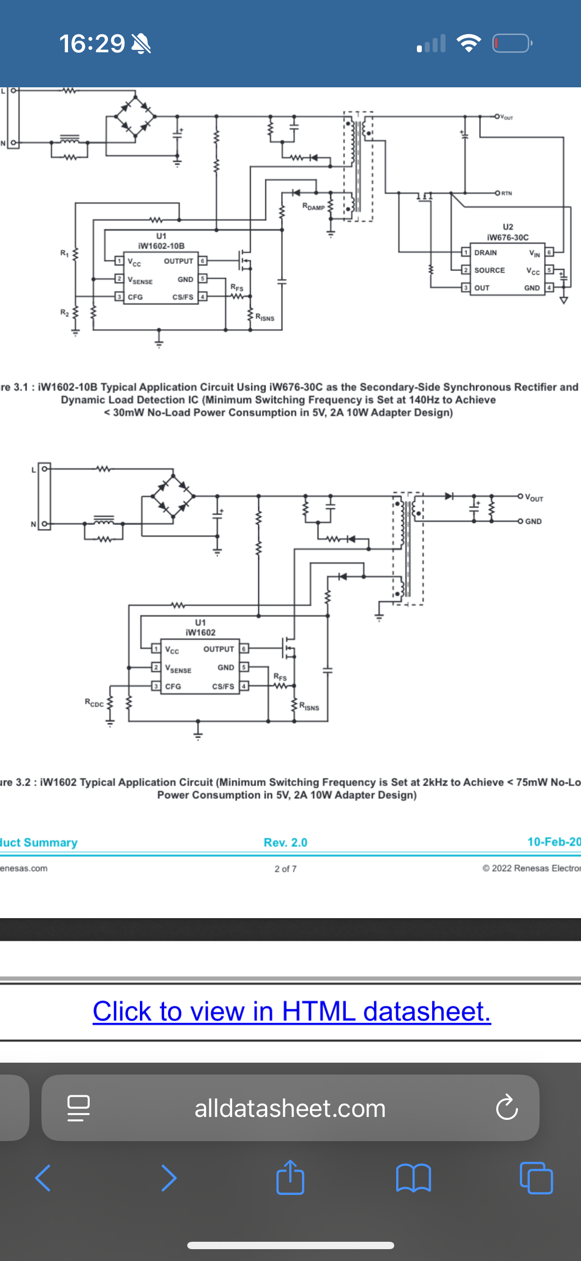
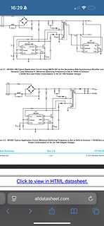
alldatasheet.com Figure 3.1 : iW1602-10B Typical Application Circuit Using iW676-30C as the Secondary-Side Synchronous Rectifier and Dynamic Load Detection IC (Minimum Switching Frequency is Set at 140H to Achieve < 30mW No-Load Power Consumption in 5V, 2A 10W Adapter Design) Figure 3.2 : iW1602 Typical
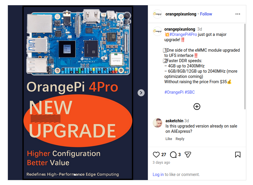
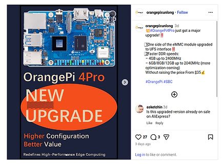
orangepixunlong Follow
orangepixunlong 3d
#OrangePi4Pro just got a major upgrade!!
1 One side of the eMMC module upgraded to UFS interface!!
2 Faster DDR speeds:
- 4GB up to 2400MHz
- 6GB/8GB/12GB up to 2040MHz (more optimization coming)
Without raising the price From $35
#OrangePi #SBC
asketchin
stroboskopet av nätfrekvensen 50 Hz. Om omkopplaren A på framsidan (se fig I) tip p a s,å t ena e lle r andra sid an ,sk all fjädernB (stämgaffeln) skenbart stå s t i l l a . (OB3 driver sakta å t ena e lle r andra h å lle t) Detta g ä llom omkopplaren s tå r i läge NETS-FREQUENZ o På instrum entets högra sida.
current of 10 A, the PAC DN006, used correctly, guarantees less than a 13 V placed on the component side of any line inductance. pulse downstream from the device. The superior Inductance resists changes in current flow such as forward voltages on the PAC DN006 account for this that of an ESD pulse. The
printers, can be connected through the PAC1284 or the PRC1284.The PACSZ1284 is the a parallel port. Both sides of this interconnection must latest addition to the family, featuring improved ESD implement a parallel port interface that is compliant withrotection, a remarkable four fold to eight fold improve-
2400 2600 kHz SW Average switch current limit V IN= VINA= 3.6 V, A = 25°C 3500 4000 4500 mA High side switch on resistance V = V = 3.6 V 50 mΩ IN INA Low side switch on resistance V IN= VINA= 3.6 V 50 mΩ Quiescent VIN and VINA IOUT = 0 mA, VEN= V IN= VINA= 3.6 25 50 μA q current V, VOUT V OUT = 3.3
ratings (unless otherwise specified, all pins are referenced to COM). parameter symbol scope unit High-side floating absolute voltage -0.3ÿ275 In VB1,2,3 High-side floating offset voltage, VS1,2,3 VB1,2,3-25ÿVB1,2,3+0.3 In high-side output voltage, VHO1,2,3 VS1,2,3-0.3ÿVB1,2,3+0.3 In low-side supply voltage
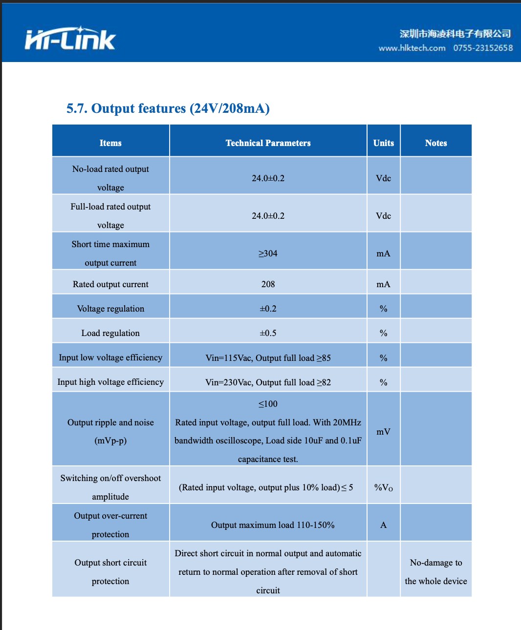
and noise (mVp-p)
Rated input voltage, output full load. With 20MHz bandwidth oscilloscope, Load side 10uF and 0.1uF capacitance test
mV
Switching on/off overshoot amplitude
(Rated input voltage, output plus 10% load) ≤
%Vo
Output over-current protection
Output maximum load 110-150%
A
Output short circuit
flash, protrusions, or gate burrs. Mold flash, protrusions, or gate burrs shall not exceed 0.25mm per side www.ti.com EXAMPLE BOARD LAYOUT DCK0005A SOT - 1.1 max height SMALL OUTLINE TRANSISTOR PKG 5X (0.95) 1 5X (0.4) 5 SYMM (1.3) 2 2X (0.65) 3 4 (R0.05) TYP (2.2) LAND PATTERN EXAMPLE EXPOSED METAL SHOWN
D3 dient als optische Anzeige des Eingangssignals. M2 (BSP89) ist ein N-MOSFET, der als Low-Side-Schalter arbeitet: Gate wird direkt vom Pulssignal angesteuert. Bei High-Pegel schaltet M2 durch und zieht den Knoten nach Masse. Dadurch entsteht ein sauberes, lastfähiges Logiksignal für
des Python-Programms öffnen, auch wenn es sich um grafische Programme mit Tkinter oder PyQt bzw. PySide handelt, wird das Kommandozeilenfenster bei Dateien mit der Dateinamenerweiterung .pyw nicht geöffnet, so daß das Programm sich mehr wie ein "richtiges GUI-Programm" anfühlt. [1] https://python.org
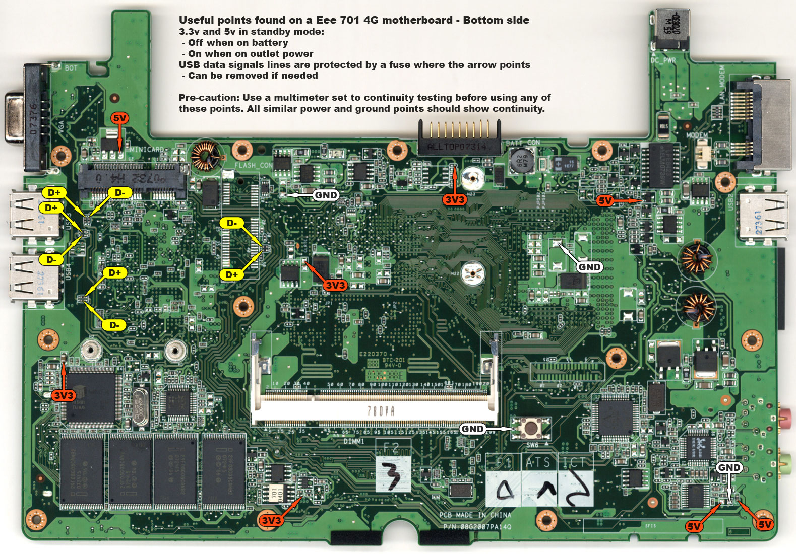
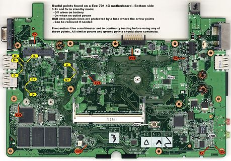
Useful points found on a Eee 701 4G motherboard - Bottom side 3.3v and 5v in standby mode: - Off when on battery - On when outlet power USB data signals lines are protected by a fuse where the arrow points - Can be removed if needed Pre-caution: Use a multimeter
Fenster in einer aufgesetzten > Metallplatte. Die erste Variante wird "Cerdip" genannt, die andere "side-brazed ceramic" - und die ist deutlich schöner anzusehen.
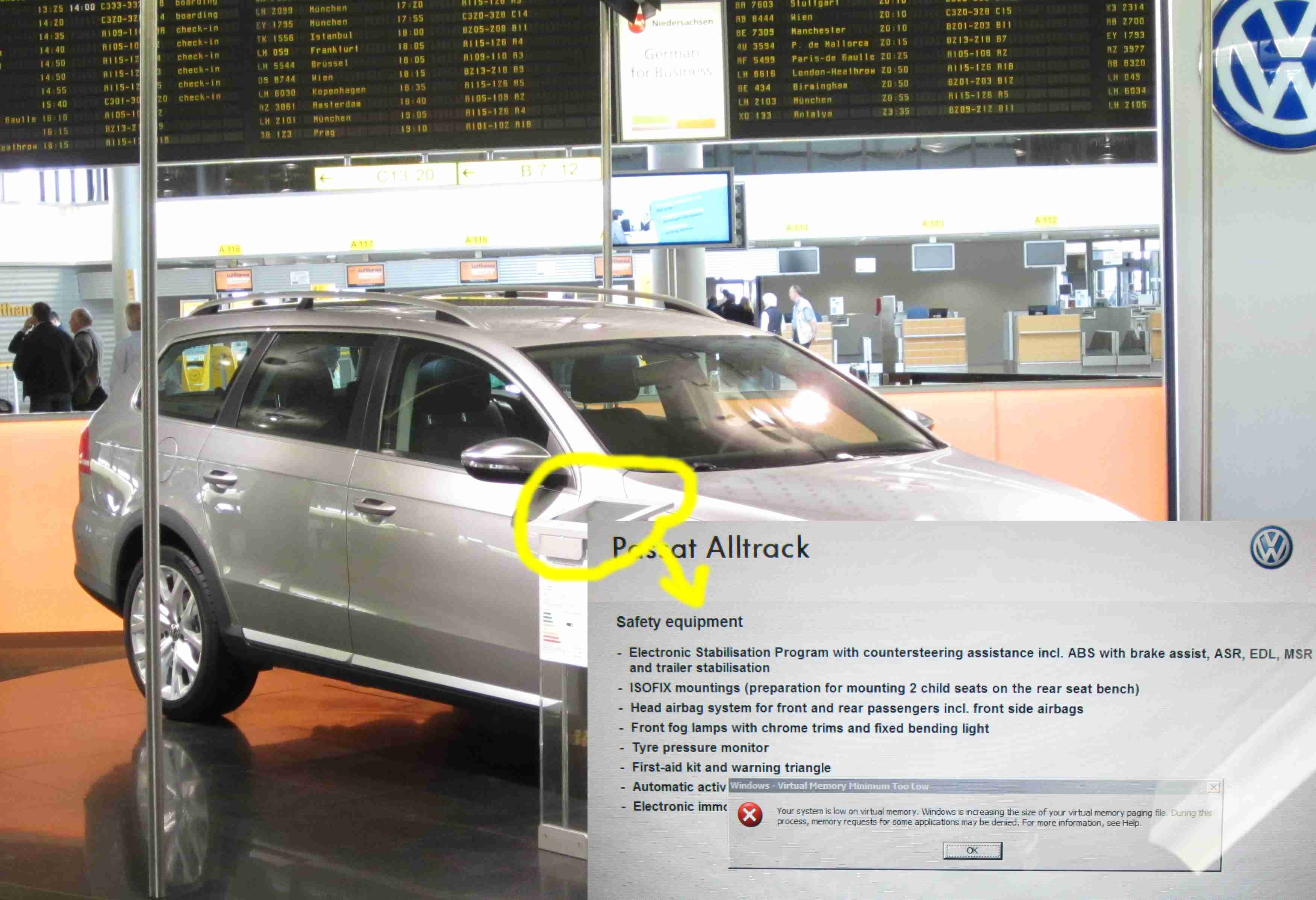
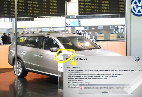
child seats on the rear seat bench)
Head airbag system for front and rear passengers incl. front side airbags
Front fog lamps with chrome trims and fixed bending light
Tyre pressure monitor
First-aid kit and warning triangle
Automatic activ
Electronic imm
the addresses from the 6502A into a pair of 74LS244s (locations B1,B3). Part two connects the other side of the ’244 to the address bus that the peripheral slots see. Also connected on this bus are the MMU, the ROM, and the chips that decode I/O SELECT, DEVICE SELECT, and I/O STROBE. The third address
1.5KExxxXX-B DO-201 500 BULK Littelfuse Spec. Tape and Reel Specification Off Center 2.56 either side.063+0.079/-0.039 (65.0) 0.028(0.7) (53.0+2.0/-1.0) 0.047 0.236 (1.2) (6.0) 0.394+/-0.020 (10.0+/-0.5) Dimensions are in 13.0 inches/mm (330.2) 3.0 (76.2) 0.68 (17.27) 2.75 (69.85) Direction of Feed
Reset CH9121 0x5e / 0xaa Leave serial port configuration mode (Only on the serial port negotiating side Formula is valid) 0x10 Setting mode: 0xaa Set chip port 1 net 00: TCP server Network mode 01: TCP client 02:UDP server 2 CH9121 Serial control instruction set 03: UDP client 0x11 Device IP address 0xaa
they should be wired close to parallel, and try to provide ground wire or copper coating on both sides to reduce external interference. The length of relevant signals of crystals XI and XO should be shortened as much as possible. In order to reduce the interference of high-frequency clock for the outside
Side-view optical bga inspection ist eine manuelle Taetigkeit und treibt halt den Preis hoch, bei Prototypen usw sinnvoll, und vielleicht bei 0 Serie. https://atecare.com/wp-content/uploads/atecare-broschure-inspectis-side-view-optical-bga-inspection-system.pdf
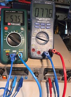
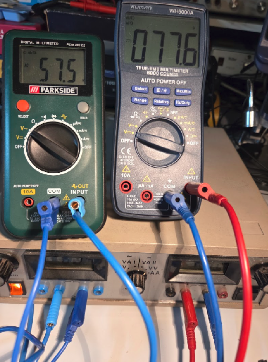
DIGITAL MULTIMETER PCM 300 CZ 57.5 PARK SIDE SELECT Ω µA mA V~ A COM INPUT AUTO POWER OFF 10A KUMAN WH5000A 077.6 TRUE-RMS MULTIMETER 8000 COUNTS AUTO POWER OFF Select Range Relative Hz/Duty OFF V~ A OFF 10A µA mA COM INPUT

 Bild
Bild
 Bild
Bild
 Bild
Bild
 Bild
Bild
 Bild
Bild
 Bild
Bild
 Bild
Bild
 Bild
Bild
 Bild
Bild
 Bild
Bild
 Bild
Bild
 Bild
Bild
 Bild
Bild