-
PDF
ESB-NE555-low-neu.pdf
in „Mal wieder: Einschaltstrombegrenzung bzw. Einschaltverzögerung für große Lasten“ · Markt ·
-
PDF
Denon-GR555-rec-sm.pdf
in „Verstärker Denon GR 555 Reparatur“ · Analoge Elektronik und Schaltungstechnik ·
-
PDF
d041048.pdf
entsprechende Vorsichtsmaßnahmen voraus- DS(ON) normalerweise eine größere Ein- tern oder einem CMOS-Timer-555 gesetzt! Ein Trenn-Regeltrafo hat sich für gangskapazität mit sich. Deshalb ist oder gar einem Mikrocontroller mit Untersuchungen an getakteten Schaltungen es nicht überraschend, dass man- weniger als
in „Cree LED an 230V“ · Mikrocontroller und Digitale Elektronik ·
-
PDF
Typ-J.pdf
1 2 3 4 5 6 7 8 9 10 240 13,000 13,056 13,111 13,167 13,222 13,278 13,333 13,389 13,444 13,500 13,555 250 13,555 13,611 13,666 13,722 13,777 13,833 13,888 13,944 13,999 14,055 14,110 260 14,110 14,166 14,221 14,277 14,332 14,388 14,443 14,499 14,554 14,609 14,665 270 14,665 14,720 14,776 14,831 14,887
in „Vref bei Sensor-Schnittstelle Thermocouple 584-AD8494ARMZ“ · Analoge Elektronik und Schaltungstechnik ·
-
PDF
150rmi.pdf
54472E3 64472E3 34472E3 6800 16 x 31 2890 683 0.25 0.019 0.130 54682E3 64682E3 34682E3 220 8 x 12 555 35 0.16 0.117 0.870 55221E3 85221E3 35221E3 330 8 x 12 555 53 0.16 0.117 0.870 55331E3 85331E3 35331E3 470 8 x 15 730 78 0.16 0.085 0.750 95475E3 95478E3 95473E3 470 10 x 12 730 78 0.16 0.097 0.680
in „Ersatz für Kondensator im Schaltnetzteil“ · Analoge Elektronik und Schaltungstechnik ·
-
PDF
igbt_app-note.pdf
The light dimmer uses an isolated gate power figure 1. Figure 1: Block schema A standard timer, a TS555 controls Short circuit protection eliminates the need conduction in the power switch. This for a fuse which would otherwise be a heat controls the light intensity. The timer is source in the circuit
in „AN- oder ABschnittsdimmer?“ · Mikrocontroller und Digitale Elektronik ·
-
PDF
igbt_app-note__alt_.pdf
The light dimmer uses an isolated gate power figure 1. Figure 1: Block schema A standard timer, a TS555 controls Short circuit protection eliminates the need conduction in the power switch. This for a fuse which would otherwise be a heat controls the light intensity. The timer is source in the circuit
in „Dimmer mit Atmel Mega“ · Mikrocontroller und Digitale Elektronik ·
-
PDF
igbt_app-note__alt_.pdf
The light dimmer uses an isolated gate power figure 1. Figure 1: Block schema A standard timer, a TS555 controls Short circuit protection eliminates the need conduction in the power switch. This for a fuse which would otherwise be a heat controls the light intensity. The timer is source in the circuit
in „Phasenan- bzw. abschnitt“ · Mikrocontroller und Digitale Elektronik ·
-
PDF
igbt_app-note__alt_.pdf
The light dimmer uses an isolated gate power figure 1. Figure 1: Block schema A standard timer, a TS555 controls Short circuit protection eliminates the need conduction in the power switch. This for a fuse which would otherwise be a heat controls the light intensity. The timer is source in the circuit
in „PWM an Triac?“ · Mikrocontroller und Digitale Elektronik ·
-
PDF
igbt_app-note.pdf
The light dimmer uses an isolated gate power figure 1. Figure 1: Block schema A standard timer, a TS555 controls Short circuit protection eliminates the need conduction in the power switch. This for a fuse which would otherwise be a heat controls the light intensity. The timer is source in the circuit
in „Triac entstören“ · Mikrocontroller und Digitale Elektronik ·
-
Datei
st96_messinstrument_e.html
controls input[type="number"] { width: 70px; padding: 4px 6px; border-radius: 4px; border: 1px solid #555; background: #111; color: #eee; font-size: 14px; } .readout { font-size: 22px; font-weight: bold; color: #fff; letter-spacing: 1px; } </style> </head> <body> <div class="meter-outer"> <div class="meter-inner
in „Suche Grafiker-Hilfe: analoge Messinstrumente nachbilden“ · Softwareentwicklung ·
-
Datei
Bauteilliste.txt
0,20.- 50Stk. 7912 -12V/1A Sp. Regl.TO220 0,15.- 9Stk. PIC16C84-04 MC Flash DIP18 1,00.- 100Stk. NE555/TLC555 Timer DIP8 0,10.- 50Stk. CD4093 C-MOS NAND Sch.Tr.DIP14 0,10.- ***Passiv 150Stk. R01JM3 Wid.Zement,0,01Ohm.3W 9x9x24 0,15.- 100Stk. 4700uF/40V Siemens ELKO 35x60 rad.M5 Anschl. 1,00.- Anm. Prod
in „[V] Bauteile THT“ · Markt ·
-
Datei
Bauteilliste2.txt
0,20.- 50Stk. 7912 -12V/1A Sp. Regl.TO220 0,15.- 9Stk. PIC16C84-04 MC Flash DIP18 1,00.- 100Stk. NE555 Timer DIP8 0,10.- 25Stk. TLC555 Timer DIP8 0,10.- 50Stk. CD4093 C-MOS NAND Sch.Tr.DIP14 0,10.- ***Passiv 150Stk. R01JM3 Wid.Zement,0,01Ohm.3W 9x9x24 0,15.- 100Stk. 4700uF/40V Siemens ELKO 35x60 rad.M5
in „[V] Bauteile THT“ · Markt ·
-
Datei
RGTL45_original.txt
586 519 550 540 577 600 541 585 530 550 562 573 576 556 616 603 550 564 569 594 571 582 558 544 554 555 544 499 586 595 556 556 585 544 590 597 548 551 560 524 566 544 528 570 563 578 537 571 567 575 570 591 555 613 537 566 545 543 507 540 547 541 555 559 545 551 538 560 542 507 531 558 514 538 521 580
in „Signal verstärken und digitalisieren - Clipping/Übersteuern“ · Analoge Elektronik und Schaltungstechnik ·
-
Datei
noname4.txt
( 2 /col ) ) ( /4B1AECC4 R3 R3 R {Lib=R} ( 1 N-000002 ) ( 2 N-000006 ) ) ( /4B1ABCD5 8dip300 U1 NE555 {Lib=NE555} ( 1 GND ) ( 2 /2 ) ( 3 N-000006 ) ( 4 VCC ) ( 5 N-000003 ) ( 6 /2 ) ( 7 N-000005 ) ( 8 VCC ) ) ( /4B1ABDE6 D3 D1 DIODE {Lib=DIODE} ( 1 N-000005 ) ( 2 /2 ) ) ( /4B1ABDCD R3 R1 R {Lib=R} (
in „KICAD: TO-92 Transistor wird in PCBnew nicht verbunden“ · Platinen ·
-
PDF
D120584B.pdf
genauso vorzunehmen, wie nachfolgend beschrieben. Stück Bauteil Wert 1 R1 2 kΩ 1 C1 100 nF 1 IC1 NE555 1 Leitgummi (grauer) 1 Anschlussplatine 1 Datavision DG 12232 LCD-Display Integrierte Schaltungen (ICs) Zunächst sollten Sie mit demVerlöten des SMD-IC NE555 beginnen.Dazu sollten Sie eines der Leiterplatten-Pads
in „Hilfe Will ein GraphikLCD 122*32 ansteuern“ · Mikrocontroller und Digitale Elektronik ·
-
Datei
Rotor.c
if(adc3 > 540) newmax = 3; //Werte der 3 Flächen des Rotors weichen etwas voneinander ab (540 und 555) else if(adc4 > 555) newmax = 4; else abbruch++; //abbruch zähler inkrementieren wenn keine Fläche "berührt" if(abbruch > 10){ //Abbruchbedingung: wenn 10 mal keine Fläche gedrückt wird, sollen new
in „Qtouch mit ADC Rotor“ · Mikrocontroller und Digitale Elektronik ·
-
PDF
lsi_part.pdf
. Figure 10 il- lustrates the power supply used for generating the upper N Channel gate drive. The 555 oscillator provides a square wave which is AC cou- pled to a diode network that is referenced to 150 Volts by the upper IN4004. The lower 1N4004 rectifies the 12 Volt peak-to-peak square wave pro- G
in „TC4451/TC4452 in Highside verwenden?“ · Analoge Elektronik und Schaltungstechnik ·
-
PDF
Temperaturmess.pdf
Gemessene Werte Gemessene Werte Ue Ua 1,236 0,812 5,000 1,328 1,128 y = 3,4459x - 3,4485 4,000 1,452 1,555 3,000 1,581 2,000 U 1,631 2,171 2,000 1,716 2,464 1,000 1,873 3,003 0,000 1,965 3,321 1,200 1,400 1,600 1,800 2,000 2,200 2,087 3,740 Ue 2,151 3,970 Kalibration mit Ue = 0,2902*Ua + 1,0008 Ua Ue Fehler Kalibration 0,812 1,236 0,000 1,128 1,328 0,000 1,555 1,452 0,000 2,500 y = 0,2902x + 1,0008 2,000 1,581 0,000 2,000 2,171 1,631 0,000 2,464 1,716 0,000 1,500 3,003 1,873 -0,001 U 1,000 3,321 1,965 0,000 3,740 2,087 -0,001 0,500 3,970 2,151 0,002 0,000
in „Suche nach einem Temperatursensor“ · Mikrocontroller und Digitale Elektronik ·
-
PDF
8660-tech-spec.pdf
43 00rters+44 172 250 4853160+49 628 795 140ORWAY +49 752 895 16770 • +33 146 587 185 • www.mas+372 555 21 121 +46 526 14025 Output voltage Utgangsspenning 12/12 VDC version Input voltage 12/12 VDC versjon Inngangsspenning Load Last Output voltage Utgangsspenning 12/24 VDC version Input voltage 12/24
in „PowerCap zur Unterstützung eines 12/24V DC-DC Spannungswandler?“ · Analoge Elektronik und Schaltungstechnik ·
-
Datei
main_program.c
stunde = 0; } } ISR (TIMER2_COMP_vect) // Interrupt wird bei einem Zählerstand von 127 ausgelöst, alle 555,555µs { k++; if (k == 300) { if (UhrzeitFreigeben == 1) { verzoegerung++; j++; if (verzoegerung == 35) { Text_ausgeben = 1; j = 69; } if (j == 90) { j = 0; } } if (TextFreigeben == 1) { verzoegerung
in „Controller kann Funktionen in anderen Files manchmal nicht aufrufen“ · Mikrocontroller und Digitale Elektronik ·
-
Datei
ov7670-regs.h
define COM15_R00FF ( 0xc0 ) // 00 to FF #define COM15_RGB565 ( 0x10 ) // RGB565 output #define COM15_RGB555 ( 0x30 ) // RGB555 output #define COM15_RGB444 ( 0x10 ) // RGB444 output #define REG_COM16 ( 0x41 ) // Control 16 #define COM16_AWBGAIN ( 0x08 ) // AWB gain enable #define COM16_DENOISE ( 0x10 ) //
in „OV7670 an STM32F102“ · Mikrocontroller und Digitale Elektronik ·
-
Datei
lochstreifen_xxd.txt
: 4e2d 5aa0 d2c5 55c6 a0b1 bd3a 42a0 ac48 N-Z...U....:B..H 0000120: 3333 bd3c a02e d24e 2d5a a0d2 c555 c6a0 33.<...N-Z...U.. 0000130: 30bd 3a42 bb41 ac42 a044 cc0a 8da0 47c5 0.:B.A.B.D....G. 0000140: 4e0a 8d41 a0c3 4253 0a8d 41ac c3a0 44cc N..A..BS..A...D. 0000150: 0a8d 35aa a053 c548 c3c9 c55a a053
-
Bild
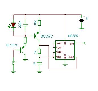
Schaltplan mit NE555 und BC557C Transistoren
220n 10k BC557C NE555 RESET VCC OUT CONT THRES GND TRIG DISC 1k 1u 5
in „Langsamer werdender Würfel“ · Analoge Elektronik und Schaltungstechnik · · Schaltpläne
-
Bild
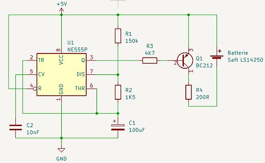
Schaltplan mit NE555P und BC212 Transistor
+5V U1 NE555P 8 VCC 2 TR 5 CV 4 R 3 Q 7 DIS 6 THR 1 GND R1 150k R3 4K7 Q1 BC212 3 2 1 R4 200R Batterie Saft LS14250 C2 10nF C1 100uF GND
in „Astabiler Multivibrator mit TLC555 (LMC555)“ · Analoge Elektronik und Schaltungstechnik · · Schaltpläne
-
Bild
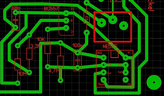
PCB-Layout eines Schaltkreises mit NE555 und BC557
68n BC557 10K 3,3M 100n 4,7M 10M NE555 GND Trig DIS Out THR Reset Ctr
in „NE555 wird heiß“ · Mikrocontroller und Digitale Elektronik · · Layouts
-
Bild
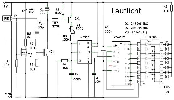
Schaltplan eines Lauflicht-Schaltkreises mit NE555 und CD4017
2N3906 EBC P1 500K R2 270K R5 100K C3 10µ R8 22 R6 10K Q3 AO3401 Q2 2N3904 EBC R7 10K R4 4M7 C2 220n NE555 6 8 4 7 3 2 1 5 C5 100n CD4017 VDD 16 3 Q0 1 2 Q1 15 MR 2 4 Q2 14 CLK 3 Q3 5 Q4 13 EN 10 Q5 12 CO 7 Q6 8 GND 6 Q7 9 Q8 11 Q9 ULN2803 18 Q0 16 Q1 15 Q2 14 Q3 13 Q4 12 Q5 11 Q6 10 Q7 9 Q8 R1 150 LED 1
in „Lauflicht, NE555, CD4017, ULN2003“ · Mikrocontroller und Digitale Elektronik · · Schaltpläne
-
Bild
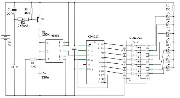
Schaltplan mit NE555, CD4017 und ULN2003
C1 220n R3 4M7 Q1 R2 2X6M8 R5 100K NE555 6 8 4 7 3 2 5 1 VCC 5V S1 4M7 C2 220n CD4017 16 3 Q0 15 MR 14 CLK 13 EN 12 CO 11 Q9 10 Q8 9 Q7 8 Q6 7 Q5 6 Q4 5 Q3 4 Q2 3 Q1 2 GND 1 Q0 ULN2003 16 1 2 15 14 13 12 11 10 9 R1 150 LED1 bis LED7
in „Lauflicht, NE555, CD4017, ULN2003“ · Mikrocontroller und Digitale Elektronik · · Schaltpläne
-
Bild
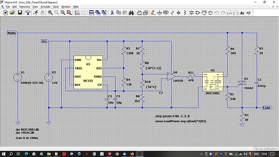
LTspice Schaltplan mit NE555, LM358 und TRIAC
LTspice XVII - moc308x_Timer555Load.asc File Edit Hierarchy View Simulate Tools Window Help Mains Vcc R5 120k R7 1k U3 GND Vcc TRIG DIS OUT RST CV U4 R11 470 U2 R9 360 R2 39 C1 0.01u V3 12V R4 12k R8 {1k*(1-x)} R10 {1k*x} C2 10n C3
in „Schwingungspaketsteuerungsfrage“ · Platinen · · Screenshots
-
Bild
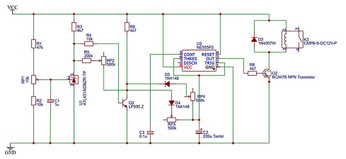
Schaltplan einer Schaltung mit NE555P3 und Transistoren
VCC R1 47k R3 4k7 R4 10k R5 200k RP2 500k U1 ATL431AIDBZR-TP C1 1u R2 10k GND U3 NE555P3 5 CONT 4 RESET 3 THRES 7 OUT 2 DISCH 1 TRIG 6 VCC GND D5 1N4148 RP4 500k R6 4k7 D4 1N4148 RP3 500k C3 0.1u C2 220u Tantal Q3 LP395 Z Q2 BC547 NPN Transistor R8 4k7 D3 1N4007W K3 CMP6-S-DC12V-P
in „Schaltbild für D+-Signal-Simulator“ · Analoge Elektronik und Schaltungstechnik · · Schaltpläne
-
PDF
SLR2016.PDF
mem- ACC Clear Disable ory. Time TCLRD 1 1 1 s A flashing circuit can easily be constructed using a 555 Clear Time TCLR 1 1 1 ms astable multivibrator. Figure 3 illustrates a circuit in which Note: T =Set Up Time + Write Time + Hold Time varying R1 (100K~10K) will have a flash rate of 1 Hz~10 Hz. ACC Loading
-
PDF
amsys.en.sm555x_e.pdf
S ILICON SM5551/SM5552 Low Pressure, Constant Current I N C O R P O R A T E D Low Pressure, Constant Voltage • L OW PRESSURE T RANSDUCER F ULLY TEMPERATURE C OMPENSATED AND C ALIBRATED DESCRIPTION Pressure sensor models SM5551 and SM5552 are fully temperature-compensated and calibrated. Each sensor is housed in a rugged plastic enclosure. Silicon Microstructures uses a unique silicon sensor chip structure to optimize low- pressure performance and to provide a true low-pressure sensor – not merely a derated high-pressure part. The result is a device low-pressure applications. Both constantfor current
in „Suche Differenzdrucksensor SM5552-003-D“ · Mikrocontroller und Digitale Elektronik ·
-
PDF
NE555_pulse_module_circuit_diagram.pdf
10kPoenomeer 10kPoenomeer
in „Hubmagnet ein/aus steuern“ · Analoge Elektronik und Schaltungstechnik ·
-
Bild
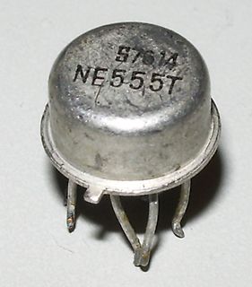
NE555T integrierter Schaltkreis im TO-5 Gehäuse
57614 NE555T
in „Der 555 wird 55“ · Analoge Elektronik und Schaltungstechnik · · Fotos
-
PDF
appl_1a.pdf
R i1 determined so that the rating of driving system provides high radiant flux and allows IINf a 555 timer IC is not exceeded, i.e. S >1V CC IN. the detection of signal variations at the rising and This pulse driving circuit uses a 555 timer IC to falling edges of pulses, thereby enabling the use of
in „Lichtsensor überprüfen aber wie?“ · Mikrocontroller und Digitale Elektronik ·
-
PDF
ERNI-IDC-Terminal-d.pdf
Holding Pte Ltd. Asien Blk 4008 Ang Mo Kio Avenue 10 #04-01/02 Techplace I Singapore 569625 Tel +65 6 555 5885 Fax +65 6 555 5995 info@erni-asia.com www.erni.com © ERNI Electronics GmbH 2012 • Printed in Germany • Technische Änderungen vorbehalten. ® ® ® ® ® ® ® ® ® ERNI , MicroStac , MicroSpeed , MiniBridge
in „Suche SMD Kontakte 10A“ · Analoge Elektronik und Schaltungstechnik ·
-
PDF
SAQ-receiver-kit-manual-ver-3.pdf
ring Zener diode BZX55C 5V1 D2, reddish, black ring Integrated circuit LM386 IC1 Integrated circuit 555 (7555) IC2 Choke 22 mH Dr1, red-red-orange-gold Choke 100 mH Dr2, black, round 2 transistors BC550C Q1, Q2 Colour code etc: Resistors R1, R3 1 MΩ Brown-black-green R2 68 Ω Blue-grey-black R4 82 Ω Grey-red-black
-
PDF
an-978_Bootstrap.pdf
the 100nF 1 8 capacitor connected between pins 1 and 8 of the +12V + VCC VB 555timergenerating -15Vreferencedtopin5of 1µF 100 RG 2 7 nF the IR2125. The charge pump circuit formed by IN 1N DUT the two lN4148 diodes and the 10nF capacitor which converts the 7.5kHz square wave at pin 3 3 6 ERR ERR CS of the 555 timer to + 15V referenced toSVnd 12V 100pF 4 RS charges the bootstrap capacitor. VSS VS 5 Figure 17 shows the circuit waveforms at start- RTN up. As the IGBT turns on, the bootstrap diode 100K 10nF
in „IR2184 half bridgde driver / Ist PWM-Signal begrenzt?“ · Mikrocontroller und Digitale Elektronik ·
-
PDF
xapp078.pdf
as described CPLD software. You can use this reference design as-is, or below. Both versions use a 555 surface-mount timer, with you can modify the design as required. Figure 3 shows the resistor and capacitor values set for 14 Hz operation. This same design done in VHDL, using the Xilinx Foundation
-
PDF
batterien.pdf
112,5 90,0 69,877 0,25156 18 0,065 3,6000 LR 44 0,25 1 11,5 5,4 5 145 1,5 0,80 2243,57 217,5 174,0 77,555 0,27920 35 0,125 6,9600 LR 43 0,25 1 11,5 4,1 5 100 1,5 0,80 1703,45 150,0 120,0 70,445 0,25360 24 0,086 4,8000 Varta V 625U 0,95 1 6,1 15,5 8 185 1,5 1,00 1811,93 277,5 277,5 153,152 0,55135 35 0,125
in „Hier mal ein Batterievergleich und Bitte um Beratung bei Batterien“ · Mikrocontroller und Digitale Elektronik ·
-
Datei
tft.c
int16_t h); void setReadDir (void); void setWriteDir (void); static uint8_t done_reset, is8347, is555, is9797; static uint16_t color565_to_555(uint16_t color) { return (color & 0xFFC0) | ((color & 0x1F) << 1) | ((color & 0x01)); //lose Green LSB, extend Blue LSB } static uint16_t color555_to_565(uint16
in „4DLCD-32QA mit STM32 initialisieren“ · Mikrocontroller und Digitale Elektronik ·
-
Datei
voltcraft_messinstrument_b.html
controls input[type="number"] { width: 70px; padding: 4px 6px; border-radius: 4px; border: 1px solid #555; background: #111; color: #eee; font-size: 14px; } .readout { font-size: 22px; font-weight: bold; color: #fff; letter-spacing: 1px; } </style> </head> <body> <div class="meter-outer"> <div class="meter-inner
in „Suche Grafiker-Hilfe: analoge Messinstrumente nachbilden“ · Softwareentwicklung ·
-
Datei
5MHz_oszi.txt
4014 3940 3448 2649 1726 905 376 252 553 1213 2082 2965 3664 4018 3941 3447 2643 1719 900 372 252 555 1217 2086 2969 3667 4020 3942 3448 2644 1721 899 370 249 552 1214 2084 2967 3666 4022 3945 3450 2647 1722 901 372 250 554 1216 2086 2968 3665 4020 3943 3449 2646 1726 903 375 252 555 1216 2085 2967
in „ADC Board für Trenz Electronic FPGA Modul“ · Projekte & Code ·
-
Datei
playCSV.html
flex-direction: column; align-items: center; justify-content: center; width: 100%; height: 400px; color: #555; font-size: 1.1rem; gap: 12px; } .placeholder svg { width: 64px; height: 64px; fill: #333; } .legend { display: flex; gap: 24px; justify-content: center; margin-top: 10px; font-size: 0.9rem; } .legend-item
in „Welches Audioprogramm kann csv-Dateien abspielen?“ · PC Hard- und Software ·
-
PDF
Gegenlauf.pdf
0,0000085 A mA µA Ω A V mV I1 = 0,0000085 = 0,009 = 8,5 U1 = 300.000 (R4) * 0,000009 (I1) = 2,56 = 2.555 I2 = 0,0011113 = 1,111 = 1.111,3 U2 = 2.200 (R2) * 0,001111 (I2) = 2,44 = 2.445 I3 = 0,0011028 = 1,103 = 1.102,8 U3 = 100 (R1) * 0,001103 (I3) = 0,11 = 110 I4 = 0,0000085 = 0,009 = 8,5 U4 = 300.000 (R5) * 0,000009 (I4) = 2,56 = 2.555 I5 = 0,0011198 = 1,120 = 1.119,8 U5 = 2.200 (R3) * 0,001111 (I6) = 2,44 = 2.445 I6 = 0,0011113 = 1,111 = 1.111,3 U6 = 4.465 (Re) * 0,001120 (I5) = 5,00 = 5.000
in „Gegenläufige Spannungen“ · Analoge Elektronik und Schaltungstechnik ·
-
PDF
HS1101LF.pdf
April 2008 3/6 HS1101LF – Relative Humidity Sensor This circuit is the typical astable design for 555. The HS1101LF, used as variable capacitor, is connected to the TRIG and THRES pin. Pin 7 is used as a short circuit pin for resistor R4. The HS1101LF equivalent capacitor is charged through R22 and
in „Sensor anschließen ?“ · Mikrocontroller und Digitale Elektronik ·
-
Bild
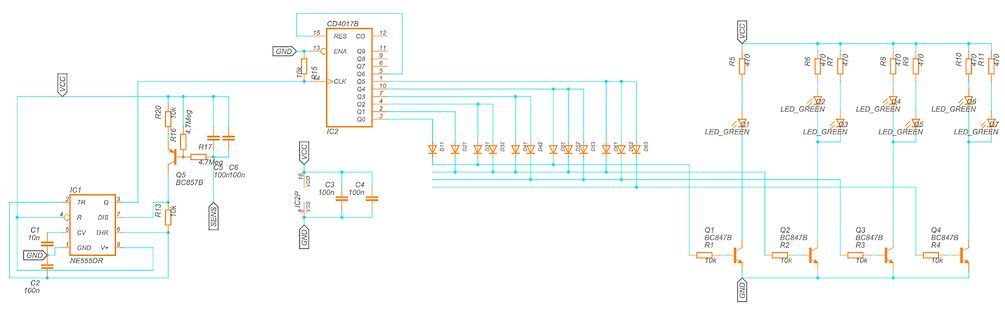
Schaltplan einer LED-Sequenzschaltung mit CD4017B und NE555
VCC, R5 bis R11, 470, LED_GREEN, D11 bis D1, IC2, C3, C4, 100n, VSS, IC1, TR, R, DIS, CV, THR, V+, NE555DR, C1, C2, 10n, 100n, R20, R16, 4.7Meg, R17, Q5, BC857B, 10k, R13, SENS, Q1 bis Q4, BC847B, R1 bis R4, 10k
in „Langsamer werdender Würfel“ · Analoge Elektronik und Schaltungstechnik · · Schaltpläne
-
Bild
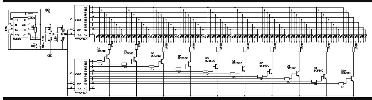
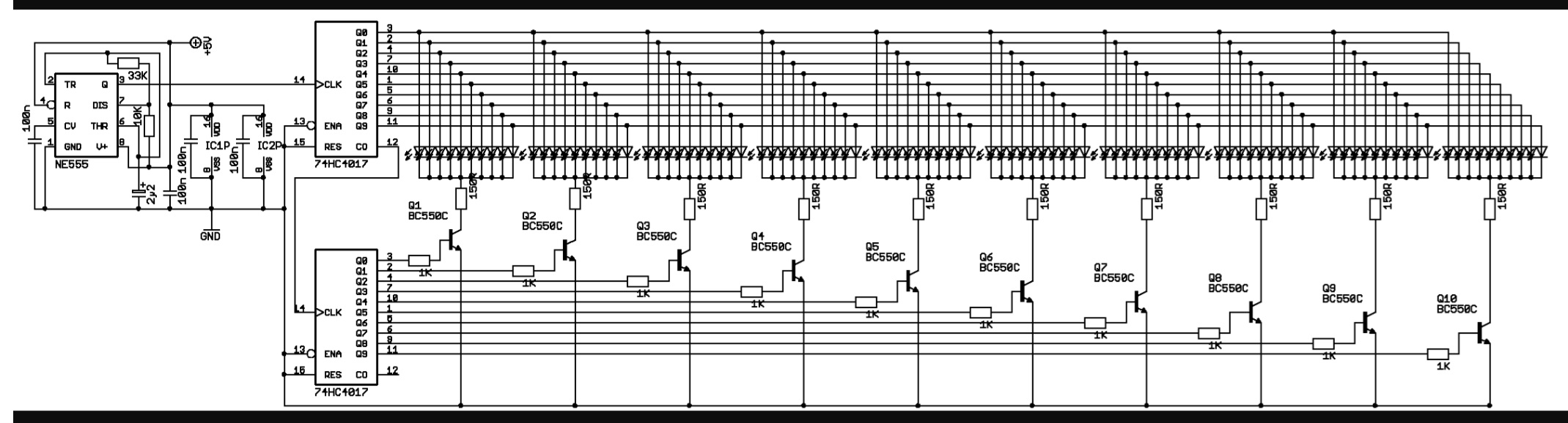
Schaltplan einer LED-Sequenzschaltung mit NE555 und 74HC4017
NE555, TR, Q, K, CV, THR, GND, V+, 100n, 10k, 22, 14, CLK, R, DIS, 13, ENA, 12, RES, CO, 74HC4017, IC1, IC2, 15R, Q1 bis Q10, BC550C, 1K
in „LED Lauflicht FET anstatt BC550?“ · Analoge Elektronik und Schaltungstechnik · · Schaltpläne