ReadthetemperaturedataintheADCdataregister,andcalculatethetemperaturevalue bythefollowingformula: Temperature (° C) = {( V - V ) /Avg_Slope} + 30- T 30 SENSE offset In which: V 30V SENSE at 30 degrees celsius Avg_Slope = temperature andAverage slope of a V SENSE curve (mV/°C or μV/°C) T offsetempirical value for
the antenna design guide and to the specific application notes for the reader IC. R1 1 OEMBoard 2 C1 LANT C3 5 C6 6 C5 C4 C8 C2 R2 6.1.3.3 Serial Interface The OEM Board can be connected directly with a micro controller. Alternatively the OEM Board also can be connected to most serial interface types
be mounted in a dry and clean place.The compressors will withstand storage temperatures down to -35°C. Condensing temperatures: Max. 60°C at stable conditions and max. 70°C at peak load. Ambient temperatures: Min. -10°C, max. 55°C The BD compressor concept includes an electronic unit which features overload
Kestler, DK1OF 1975/2 66 - 77 Description 70 cm Band A Simple 70 cm Power Amplifier Equipped with the 2C39 K Weiner, DJ9HO 1975/2 78 - 82 70 cm Band A Versatile 70 cm Converter with Schottky Diode Mixer B Lubbe, DJ5XA 1975/2 83 - 89 Amateur Television A Veratile 70 cm Converter with Schottky Diode Mixer
1.3V to 3.6V X1 1 10 VCC • Low Typical Timekeeping Current: X X2 2 5 9 MFP - Operating from V: 1.2 µA at 3.0V 9 - Operating from VT: 1.0 µA at 3.0V VBAT 3 P 8 SCK • Automatic Switchover to Battery Backup CS 4 C 7 SO M VSS 5 6 SI User Memory • 64-Byte Battery-Backed SRAM • 1 Kbit or 2 Kbit EEPROM: Note:
time to get to level 6 (except S9, which had data, and should be considered unreliable [77]. A chip at this state only reached 5 at the camera-ready due date); we took every device could stop functioning at any moment. all the way to 11, except the S6 and S9. Timing results vary, even We repeatedly issued
the maximum output power. 2) Maximum continuous power in a non-ventilated enclosed adapter measured at 50°C ambient temperature. 3) Maximum continuous power in an open frame design at 50°C ambient temperature. HF500-30 Rev.1.01 www.MonolithicPower.com 1 8/6/2019 MPS Proprietary Information. Patent Protected
. Also auch die AT89C51xxx haben ernsthafte Macken. Ob sich das mit den ständig neuen AVR-Serien von Microchip verbessert hat, kann ich nicht sagen. https://www.robotroom.com/Atmel-AVR-TWI-I2C-Multi-Master-Problem.html
haben aber noch zusätzlich einen Message-FIFO im SRAM angelegt. Später haben wir den AT89C51CC03 und den AT90CAN128 verwendet. Der CAN-Controller ist bei allen 3 gleich aufgebaut, d.h. auch 15 MOBs. Zur Programmierung gibt es nicht viel zu sagen. Man setzt die Timingregister für die
A DATA A DATA A P W R AcknowledgefromRV-3032-C7 May 2023 124/154 Rev. 1.3 Micro Crystal DTCXO Temp. Compensated Real-Time Clock Module RV-3032-C7 6.8. READ OPERATION AT SPECIFIC ADDRESS Master reads data from slave RV-3032-C7 at specific address:
the I2C 2002-1A Evaluation Board Kit at www.demoboard.com DesignCon 2003 TecForum I C Bus Overview 89 Slide 89 2 Low Power version of the SMBus Specification only Comparison of I C with SMBus The SMBus specification
of a device of the series contains information as depicted below: Figure 1-2. Device Designations AT tiny1617 - MNR Carrier Type Package up to 24 pins R=Tape & Reel Flash size in KB Temperature Range tinyAVR series N=-40°C to +105°C F=-40°C to +125°C Pin count Package Type 7=24 pins M=QFN 6=20 pins
,abhängigvomSo- der Platine löten. 51 Personal Download for Hans-Jürgen Heidenreich | copyright Elektor Stückliste Widerstände R1 = 100 k R2 = 10 k R3 = 47 k P1 = Poti 1 M, linear Kondensatoren C1 = 22 µ/25 V dem Fall über 3 V liegen, von
NOTICE. THE PRODUCTS DESCRIBED HEREIN AND THIS DOCUMENT ARE SUBJECT TO SPECIFIC DISCLAIMERS, SET FORTH AT www.vishay.com/doc?91000 VS-E5PH6006L-N3 www.vishay.com Vishay Semiconductors 1000 C 180 ) ( p r 170 ( t c r 160 a e i m a e 150 a T DC C 100 a 140 n P t e 130 c l u S 120 Square wave (D = 0.50) - e
pins, two on each side of the connector. To avoid confusion, the first two pins are defined as Pin C0 and Pin D0. The additional ground pins at the end of the connector are defined as C19 and D19. The pinout between PC/104 bus and AT ISA bus is identical between C1 - C18 and D1 - D18. The MOPS/386A
fixed on the front side or on the bottom of the tank. The preset switch-off temperature is approx. 60°C. If the temperature rises above 70°C during operation without cover (contact permanently closed), or if the unit does not heat at all (contact permanently opened), the thermostat is probably faulty.
- Time (ms) Fig. 1 - Peak Pulse Power Rating Curve Fig. 3 - Pulse Waveform )P 100 6000 IP Measured at t ) Zero Bias e p r , 75 e C ge c1000 r t t ) e c P r p ( P 50 a e n C w g i V , Measured at Stand-Off P t c 100 Voltage V e r u WM l e 25 - P D J Uni-Directional TJ= 25 °C k C Bi-Directional f = 1.0
Kanal A 34 22 DA1 Enc-05 Fehler Kanal B 35 23 DA1 Enc-06 Fehler Kanäle A und B 40 28 DA1, DB1, DC1 AtF-01 Motor-Identifikation nicht erfolgreich 41 29 DA1, DB1, DC1 AtF-02 Motor-Identifikation nicht erfolgreich: Der gemessene Statorwiderstand ist zu groß. 42 2A DA1, DB1, DC1 AtF-03 Motor-Identifikation nicht erfolgreich: Die gemessene Motorinduktivität ist zu niedrig. 43 2B DA1, DB1, DC1 AtF-04 Motor-Identifikation nicht erfolgreich: Die gemessene Motorinduktivität ist zu groß. 44 2C DA1, DB1, DC1 AtF-05 Motor-Identifikation nicht erfolgreich: Die gemessenen Motorparameter passen nicht
+125 °C TOPR Operating Temperature −40 to +85 °C TJ Junction Temperature Range −40 to +100 °C TSOL Lead Solder Temperature 260 for 10 seconds °C PD Total Device Power Dissipation at 25°C Ambient 330 mW Derate Above 25°C 4.4 mW/°C EMITTER IF Continuous Forward Current 60 mA VR Reverse Voltage 3 V PD Total Power Dissipation at 25°C Ambient 100 mW Derate Above 25°C 1.33 mW/°C DETECTOR V Off−State Output Terminal Voltage
bitten/betteln wird auf Dauer einen zermürben. Meine längste Suche nach einem Assemblerbug (war aber AT89C52) lag bei ein paar Wochen mit vielen Unterbrechungen – am Ende waren es zwei Bitverschiebungen, die die Bits auf der anderen Seite wieder eingeschoben haben (allgemein als ROR/ROL bekannt), was ich
nach alles bis dato Erstellte auf C umgeschrieben. Vor den AVRs kannte ich aber schon Assembler und habe entsprechend programmiert – 8085, Z80, 6502, 68000, µC51. AVR-Assembler (der 8-bitter) ist auf jeden Fall etwas freundlicher und einfacher
Ich hab auch oft alten C51 Code auf anderen MCs wieder verwendet. Z.B. generisches I2C, SPI mit einfachen IO-Pins. Das spart deutlich Arbeit gegenüber jedesmal den Code für die Hardware-Einheiten anderer MCs umschreiben zu müssen
deutlich CPU-Zeit noch Flash ein. Bzw. der > Code wird sogar größer, > Ich hab auch oft alten C51 Code auf anderen MCs wieder verwendet. Z.B. > generisches I2C, SPI mit einfachen IO-Pins. Das spart deutlich Arbeit Das klingt nicht unbedingt nach professioneller Programmierung sondern eher
bewegen. Ich hatte mal einen Glasmeßstab für Positionierung im µm Bereich auslesen müssen, da hat ein AT89C51 mit 50kHz Interrupt völlig gereicht.
> Ich hatte mal einen Glasmeßstab für Positionierung im µm Bereich > auslesen müssen, da hat ein AT89C51 mit 50kHz Interrupt völlig gereicht. Damit gehörst Du nicht zu der Zielgruppe meines Vorschlages. 50 kHz können schon von inkrementalen Kurzhubtastern (beispielsweise Heidenhain MT12, MT25)
connected to SS BS0, BS2, CL, D[7:3], E, R/W#, CS#, D/C#, BGGND Pin internally connected to DD: BS1, CLS V BAT,C1P, C1N, C2P, C2N, V BREF, FR should be left open. C1, C2: 2.2uF (1) (1) C3: 1.0uF R P Pull up resistor Voltage at REF = VCC – 2.5V. For VCC= 7.5V
Software benutze ich „AVRDUDE“ Version 7.1 mit Erweiterung von avrdue.conf für die Mikrocontroller AT89S51/52 [code] avrdude -c usbasp -p 8052 -U flash:r:test.hex:i avrdude warning: a1 would normally be expected to be a9 [E:\Baben\Dokumentation\ELEKTRO\Mikrokontroller\ATmega\AT89S51 flashen\Software
warning: a0 would normally be expected to be a8 [E:\Baben\Dokumentation\ELEKTRO\Mikrokontroller\ATmega\AT89S51 flashen\Software\AVRDUDE\avrdude.conf:16252] avrdude warning: mcuid -1 for AT89S51 is out of range [0..2039], use a free number >= 372 [E:\Baben\Dokumentation\ELEKTRO\Mikrokontroller\ATmega\AT89S51
ausgebauten Übertragungsnetz und damit auch zur Vermeidung von Engpassmanagement bei. BUNDESNETZAGENTUR | 89 Prüfungsergebnisse DC40plus A 2037 B 2037 C 2037 Überlastungsindex - 540 GWh - 950 GWh - 1170 GWh Leistungsfluss Maximum 2000 MW 2000 MW 2000 MW Auslastung 100 % 100 % 100 % A 2045 B 2045 C 2045 Überlastungsindex
at core/timeouts.c line 241 0x40201047: updatePWM() at C:\Users\alex\Documents\Arduino\OhneFehler/OhneFehler.ino line 54 0x402014f4: Ticker::_static_callback() at C:\Users\alex\AppData\Local\Arduino15
0x401000ab: app_entry_redefinable() at C:\Users\alex\AppData\Local\Arduino15\packages\esp8266\hardware\esp8266\3.1.2\cores\esp8266\core_esp8266_main.cpp line 386 0x4010015c: ets_post(uint8, ETSSignal, ETSParam) at C:\Users\alex\AppData\Local
Peter D. schrieb im Beitrag #7603117: > Dabei gibt es durchaus leistungsfähige 8051, z.B. AT89LP51RD2 (20 MIPS). Lahme Gurke! ;-) https://www.silabs.com/mcu/8-bit-microcontrollers/c8051f12x-f13x
bei https://community.arm.com/support-forums/f/keil-forum/16125/how-to-disable-startup-code-for-p89c51rd2hbp

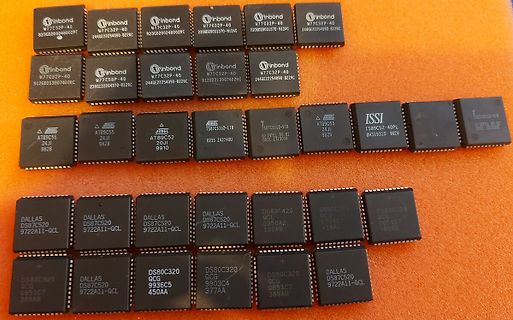
 Bild
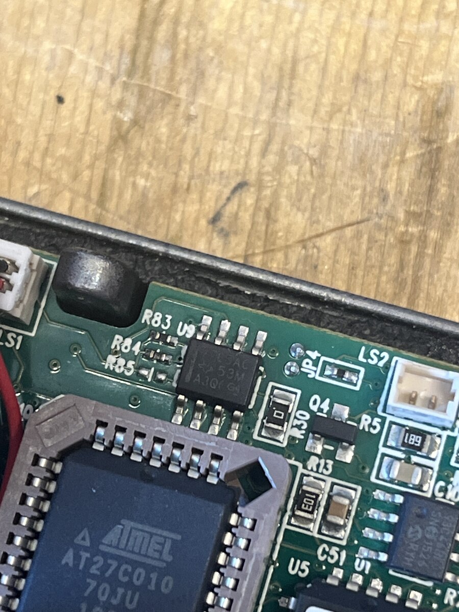
Bild
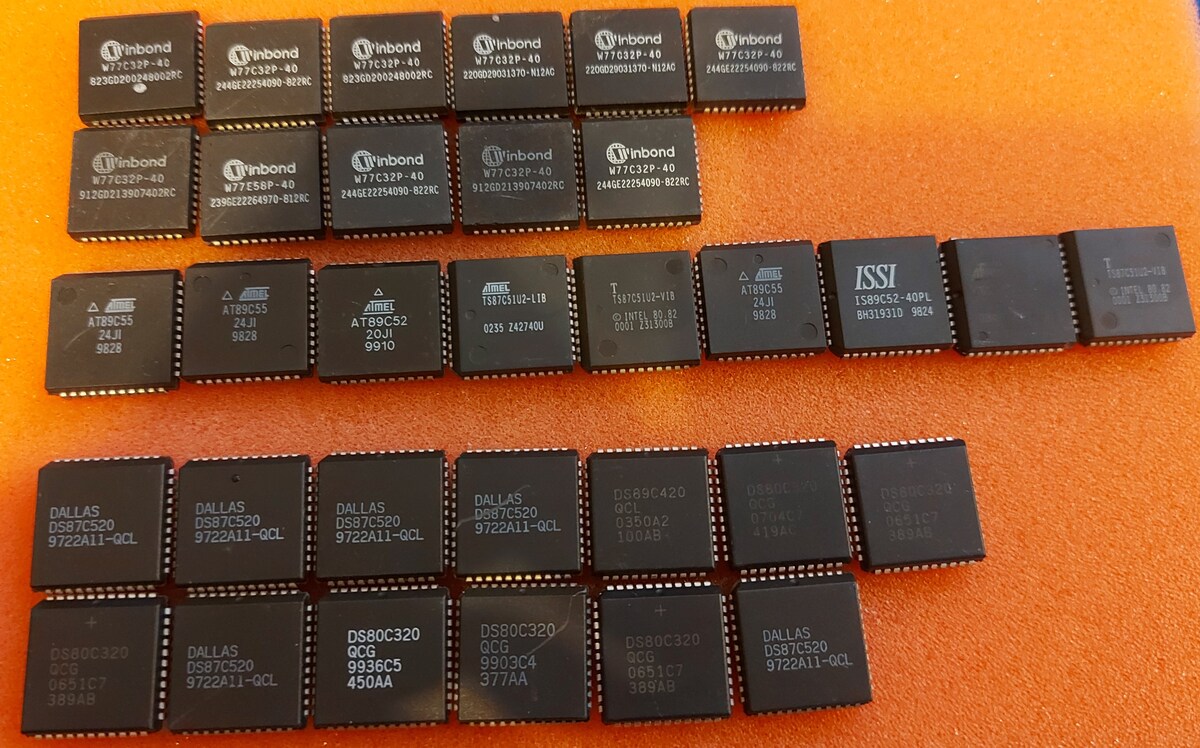
 Bild
Bild