-
Datei
PID_3.3_Multicycles.txt
--------------- Config Porte.0 = Input Config Porte.1 = Output Config Serialin = Buffered , Size = 128 Config Serialout = Buffered , Size = 128 ' ------------------------------------------------------------------------------ ' ----[Configure the LCD screen]--------------------------------------------
in „Frage Regelungstechnik: dynamische Systeme“ · Mikrocontroller und Digitale Elektronik ·
-
PDF
Atmega128_doc2467.pdf
from the Stack, the Stack Pointer is incre- mented by two, and the I-bit in SREG is set. 17 2467R–AVR–06/08 AVR This section describes the different memories in the ATmega128. The AVR architecture has two ATmega128 main memory spaces, the Data Memory and the Program Memory space. In addition, the ATmega128
in „ATMEGA128 Timer“ · Mikrocontroller und Digitale Elektronik ·
-
PDF
PWM_Controller_Manual_Basic.pdf
Seiten „CMD- Beispiele“ . Das TWI- Protokoll Slave Receiver Modus Es lassen sich je Zugriff maximal 128 Byte transportieren. Sende = Empfangsbuffer = 128 Byte. 1) Schreiben (Register 0x00 bis 0x80) und (0xC0 bis 0xDD). 2) Lesen (Befehle 0x00 bis 0x80). 1) Schreiben Ein einfacher Schreibbefehl besteht
in „PWM- Controller 18- Kanal TWI- Bus Proj.“ · Projekte & Code ·
-
Datei
kb.c
/* this keyboard interface is based on avr appnote 313 changes are made for using avr-gcc and atmega8 processors beck@informatik.htw-dresden.de */ #include <device.h> /* ***********************************************************************
in „PS/2 Keyboard am PSoC 3/4/5“ · Mikrocontroller und Digitale Elektronik ·
-
Datei
main.cpp
// --- AVR128DB64 --- #include <avr/io.h> #include <avr/interrupt.h> #include <util/atomic.h> void initPins (void); void initTCA0 (void); void deleteTCA0 (void); int main (void) { deleteTCA0(); initPins(); initTCA0
in „GCC v14 Release“ · Mikrocontroller und Digitale Elektronik ·
-
Datei
I2C_display.h
mit PCF8574 // RS Low - Steuerbefehl // RS=High Ascii ab Adresse-0x80=1.Zeile + 1.Spalte #include <avr/io.h> #include <stdlib.h> //#include "display.h" // für alle Display bis 4x20 #include <util/delay.h> #include <avr/interrupt.h> #include "I2C_Master.h" #define LCD_CMD 0b00000000 // RS = LOW #define
in „LCD 4x40 ansteuern über PCF8574 (I2C)“ · Mikrocontroller und Digitale Elektronik ·
-
Datei
Ansteuerung_SED1374.asm
.db $C0,$C8,$10,$20,$40,$98,$18,$00 ; % .db $60,$90,$A0,$40,$A8,$90,$68,$00 ; & .db $60,$20,$40,$00,$00,$00,$00,$00 ; Ž .db $10,$20,$40,$40,$40,$20,$10,$00 ; ( .db $40,$20,$10,$10,$10,$20,$40,$00 ; ) .db $00,$20,$A8,$70,$A8,$20,$00,$00 ; * .db $00,$20,$20,$F8,$20,$20,$00,$00 ; + .db $00,$00,$00,$00,$60,$20,$40,$00 ; , .db $00,$00,$00,$F8,$00,$00,$00,$00 ; - .db $00,$00,$00,$00,$00,$60,$60,$00 ; . .db $00,$08,$10,$20,$40,$80,$00,$00 ; / .db
in „Strings im Flash“ · Mikrocontroller und Digitale Elektronik ·
-
 Bild
Bild
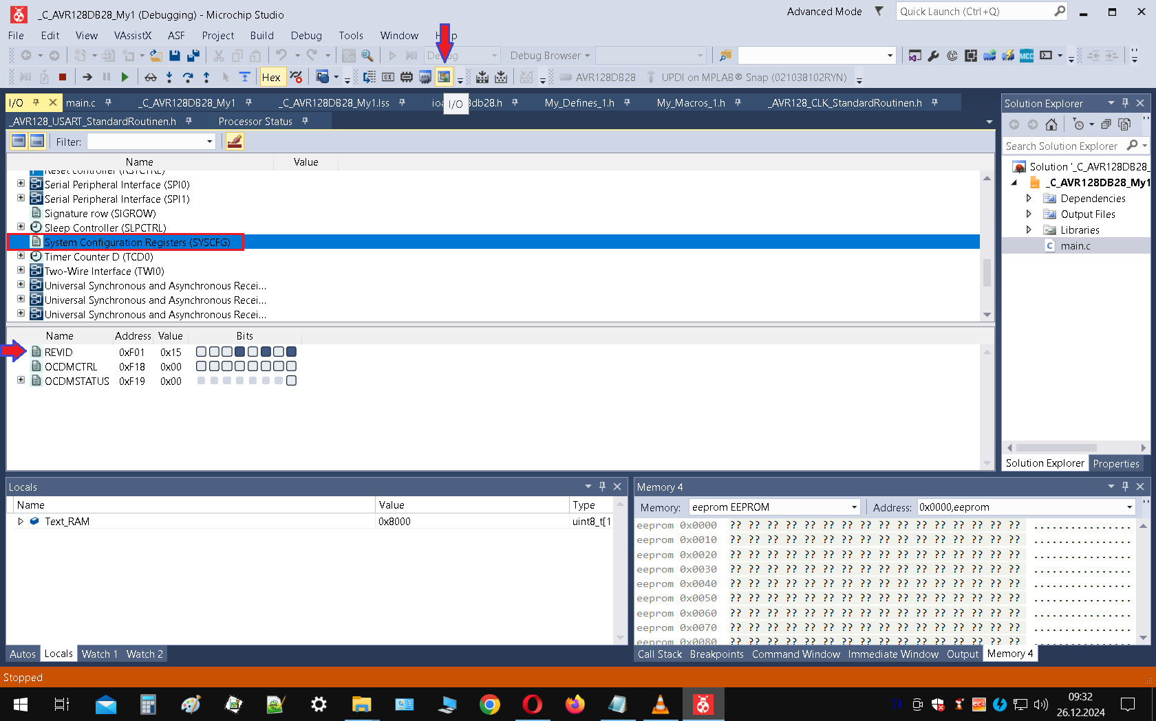
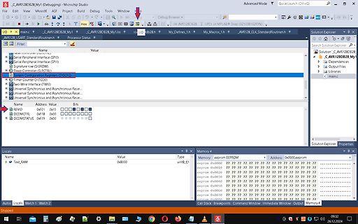
Microchip Studio Debugger Ansicht
Microchip Studio, AVR128DB828_My1, Debugger, Watch, Memory, eeprom, 0x8000, 0x0000
in „AVR128DA64 TCA1 funktioniert nicht mit alternativen Output?“ · Mikrocontroller und Digitale Elektronik · · Screenshots
-
 Bild
Bild
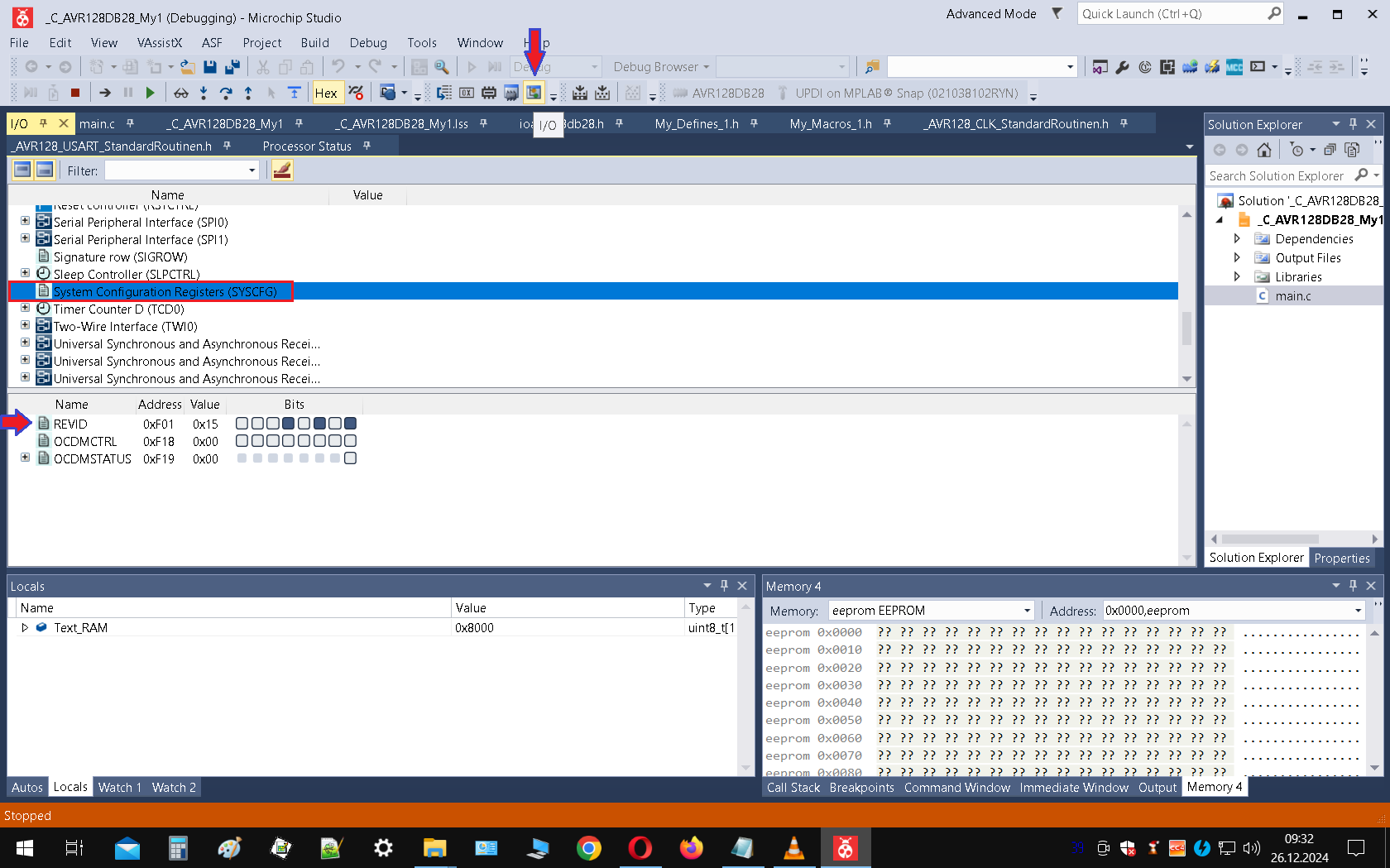
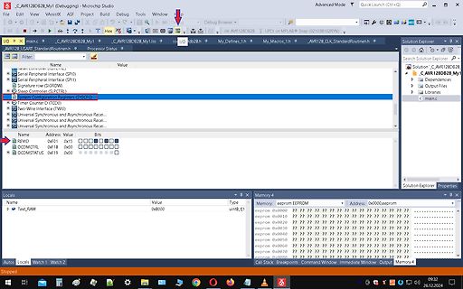
Microchip Studio Debugger Ansicht
Microchip Studio, AVR128DB82, Debugger, Watch, Memory, eeprom, 0x0000, 0x8000
in „welcher Debugger für 8bit Controller (AVR etc.) ?“ · Mikrocontroller und Digitale Elektronik · · Screenshots
-
Datei
Z80int-jmp.asm
... .equ ZFL_S = 7 .equ ZFL_Z = 6 .equ ZFL_H = 4 .equ ZFL_P = 2 .equ ZFL_N = 1 .equ ZFL_C = 0 .equ AVR_T = SREG_T .equ AVR_H = SREG_H .equ AVR_S = SREG_S .equ AVR_V = SREG_V .equ AVR_N = SREG_N .equ AVR_Z = SREG_Z .equ AVR_C = SREG_C ; TODO: check Z80 flag settings ;----------------------------------
in „CP/M auf ATmega88“ · Mikrocontroller und Digitale Elektronik ·
-
Datei
Unterprogramme.h
UCSR1A #define UART1_CONTROL UCSR1B #define UART1_DATA UDR1 #define UART1_UDRIE UDRIE1 #elif defined(__AVR_ATmega64__) || defined(__AVR_ATmega128__) /* ATmega with two USART */ #define ATMEGA_USART0 #define ATMEGA_USART1 #define UART0_RECEIVE_INTERRUPT SIG_UART0_RECV #define UART1_RECEIVE_INTERRUPT SIG_UART1
in „Roboter-Linienverfolgung mit P-Regler und Ausweichmodus“ · Mikrocontroller und Digitale Elektronik ·
-
Datei
level1test.asm
============== ; ; start: ; ; Init ; ldi r18, low(RAMEND) out CPU_SPL, r18 ldi r18, high(RAMEND) ; AVR128DA does this during RESET out CPU_SPH, r18 ; ; Set CPU Clock Frequency ; ldi r18, CPU_CCP_IOREG_gc sts CPU_CCP, r18 ldi r18, F_CLK sts CLKCTRL_OSCHFCTRLA, r18 ; ; Constants ; clr zero ;===========
in „AVR Level1 Interrupt“ · Mikrocontroller und Digitale Elektronik ·
-
Datei
Voltmeter_2016_07_24_v3.c
Wert 25000, PWM-Frequenz daher 1000000/25000= 160 Hz. 2* RC-Filter unterdruckt 12 dB/Okt, daher 72 dB braucht 6 Okt., F_Filter = 2,5 (2,2)Ãö. 2,2u 33k, RC = 0,0726 s 10 RC = 0,726 s. 2 RC = 0,1452 s. */ #define F_CPU 4000000UL // CPU_F fuer Verzoegerungen #include <avr/io.h> // Muss immer sein #include <util/delay.h> // Fuer verzoegerungen #include <avr/interrupt.h> // Fuer Interrupts #include <avr/pgmspace.h> // Fuer Const. in Flash #include <avr/eeprom.h> // Fuer eeprom #include "global.h" // Globale Variablen und Konst. #include "Ind_stat.h" //
in „Eine "Kinderfrage" bzg. *.h und *.c“ · Mikrocontroller und Digitale Elektronik ·
-
Datei
lcd-routines.h
angeschlossen sein und die 4 // Datenleitungen müssen auf aufeinanderfolgenden Pins liegen // LCD DB4-DB7 <-> PORTD Bit PD0-PD3 #define LCD_PORT PORTD #define LCD_DDR DDRD #define LCD_DB PD0 // LCD RS <-> PORTD Bit PD4 (RS: 0=Data, 1=Command) #define LCD_RS PD4 // LCD EN <-> PORTD Bit PD5 (EN: 1-Impuls
in „error: stray ‘\327′ in program“ · Mikrocontroller und Digitale Elektronik ·
-
Datei
lcd-routines.h
angeschlossen sein und die 4 // Datenleitungen müssen auf aufeinanderfolgenden Pins liegen // LCD DB4-DB7 <-> PORTD Bit PD0-PD3 #define LCD_PORT PORTD #define LCD_DDR DDRD #define LCD_DB PD0 // LCD RS <-> PORTD Bit PD4 (RS: 0=Data, 1=Command) #define LCD_RS PD4 // LCD EN <-> PORTD Bit PD5 (EN: 1-Impuls
in „error: stray ‘\327′ in program“ · Mikrocontroller und Digitale Elektronik ·
-
PDF
kicad_8450_dcm_liste_neu_v3.pdf
-20PU PDIP14, 2k Flash, 128B SRAM, 128B EEPROM, dW ATTINY24-20SSU SO14, 2k Flash, 128B SRAM, 128B EEPROM, dW ATTINY24A-MMH VQFN20, 2k Flash, 128B SRAM, 128B EEPROM, dW ATTINY24A-MU QFN/MLF20, 2k Flash, 128B SRAM, 128B EEPROM,
in „KiCAD Eeschema, Bibliotheksdokumentation *.dcm als PDF-Datei“ · Platinen ·
-
Datei
ssd1306.c
-> 14.04.2018 09:13:07 * Description -> Treiber unterstützt das I2C Protokoll. * * * */ #include <avr/io.h> #include <avr/interrupt.h> #include <string.h> #include <stdlib.h> #include "I2C.h" #include "ssd1306.h" static uint8_t DisplayRam[ ( SSD1306_LCD_Width * SSD1306_LCD_HEIGHT ) / 8 ] = "0xFF"; static
in „SSD1306/1309 Library zum Darstellen von Text auf OLED Displays“ · Projekte & Code ·
-
Datei
iocan128.h
) - AT90CAN128 Datasheet (bit defines and register addresses) - Appnote on Mega128 --> AT90Can128 Conversion (for what registers I need to change) */ /* iocan128.h - definitions for CAN128 */ #ifndef _AVR_IOCAN128_H_ #define _AVR_IOCAN128_H_ 1 /* This file should only be included from <avr/io.h>, never directly. */ #ifndef _AVR_IO_H_ # error "Include <avr/io.h> instead of this file." #endif #ifndef _AVR_IOXXX_H_ # define _AVR_IOXXX_H
in „CANIDT1 undeclared“ · Mikrocontroller und Digitale Elektronik ·
-
Datei
main.c
#include <avr/io.h> #include <avr/interrupt.h> #include <stdlib.h> #include <stdio.h> #include "lcd-routines.h" #define PHASE_A (PIND & 1<<PIND5)//(PINC & 1<<PINC0) // PINC.0 #define PHASE_B (PIND & 1<<PIND6)//(PINC & 1<<PINC1) // PINC.1 volatile char enc_delta; // -128 ... 127 unsigned short count; //neu /* Für später (Zerlegung der eingestellten Zahl in Vor-/Nachkommastelle) uint8_t einer=0; uint8_t zehner=0; uint8_t hunderter=0; uint8_t nachkomma=0; */ char Buffer
in „AVR: Drehgeber-Verhalten bei sehr schnellem Wechsel“ · Mikrocontroller und Digitale Elektronik ·
-
Datei
8080int-jmp.asm
... .equ ZFL_S = 7 .equ ZFL_Z = 6 .equ ZFL_H = 4 .equ ZFL_P = 2 .equ ZFL_N = 1 .equ ZFL_C = 0 .equ AVR_T = SREG_T .equ AVR_H = SREG_H .equ AVR_S = SREG_S .equ AVR_V = SREG_V .equ AVR_N = SREG_N .equ AVR_Z = SREG_Z .equ AVR_C = SREG_C ; TODO: check Z80 flag settings ;----------------------------------
in „CP/M auf ATmega88“ · Mikrocontroller und Digitale Elektronik ·
-
Datei
TCBn_32Bit_Counter_Pulsweite_cascaded_ErrorTest_Form.ino
/* Arduino IDE 1.8.13 avr-gcc 10.2.0 AVR128DB48 Curiosity Nano Board https://github.com/SpenceKonde/DxCore 32Bit TCB Counter Pulsweitenmessung Taktausgang von TCA1: Pin PC4 Takteingang für TCB: Pin PA4 27.11.2020 https://www.mikrocontroller.net/topic/505708 */ #include <avr/io.h> #include <avr/interrupt.h> #include <util/atomic.h> volatile unsigned long countTimerCCMP_LSB; volatile unsigned long countTimerCCMP_MSB; volatile unsigned long countTimerTotal; volatile bool
in „AVR128DB48 - TCB 32Bit Counter“ · Mikrocontroller und Digitale Elektronik ·
-
Datei
Schrittmotor.asm
OVF ;0x0044 ; Timer3 Overflow ; reti ;rjmp Posit -Test- ;Zurueck: .ORG 0x0100 ; Adresse 0x200 MTab: .db 0,2,3,5,6,8,9,11,13,14,16,17,19,20,22,24,25,27,28,30,31,33,34,36,38,39,41,42,44,45,47,48 .db 50,51,53,55,56,58,59,61,62,64,65,67,68,70,71,73,74,76,77,79,80,82,83,85,86,88,89,91,92,94,95,96 .db 98,99,101,102,104,105,107,108,109,111,112,114,115,116,118,119,121,122,123,125,126,128,129,130,132,133,134,136,137,138,140,141
in „Spielerei mit einem 2- und 5-Phasen-Schrittmotor“ · Projekte & Code ·
-
Datei
main.c
SCL_CLOCK 100 #define F_CPU 8000000 #include<5x8_vertikal_LSB_1.h> #include<util/delay.h> #include<avr/io.h> #include<i2cmaster.h> void write_string_to_OLED_buffer(unsigned char*, char*); unsigned char print_buffer_to_OLED(unsigned char*); unsigned char initialize_OLED(void); int main (void) { unsigned
in „Pointer an Funktion übergeben AVR C“ · Mikrocontroller und Digitale Elektronik ·
-
Datei
TCB_32Bit_Counter_Pulsweite.ino
/* Arduino IDE 1.8.13 AVR128DB48 Curiosity Nano Board https://github.com/SpenceKonde/DxCore 32Bit Counter Takteingang Pin PA4 Interruptmesspin für Oszi PB3 und PC3 */ #include <avr/io.h> #include <avr/interrupt.h> #include <
in „AVR128DB48 - TCB 32Bit Counter“ · Mikrocontroller und Digitale Elektronik ·
-
Datei
avr_oscilloscope_1_.htm
style="LINE-HEIGHT: 100%; MARGIN-TOP: 0px; MARGIN-BOTTOM: 0px" align=left><IMG border=0 src="images/avr_oscilloscope_htm_avr_osc_html_smartbutton1.gif" namo_npi=":EmbededNPI001"> </P> <P style="LINE-HEIGHT: 100%; MARGIN-TOP: 0px; MARGIN-BOTTOM: 0px" align=left> </P> <P style="LINE-HEIGHT: 100%; MARGIN-TOP
in „AVR-OZZI_fuses_help“ · Mikrocontroller und Digitale Elektronik ·
-
Datei
mv_gcctest9.lst
@gmx.de 12:mv_gcctest9.c **** You might find more AVR related stuff at my homepage: 13:mv_gcctest9.c **** http://members.xoom.com/volkeroth 14:mv_gcctest9.c **** */ 15:mv_gcctest9.c **** 16:mv_gcctest9.c **** #include "uart.h" 17:mv_gcctest9.c **** #include <avr/pgmspace.h> 18:mv_gcctest9.c **** #include <avr/io.h> 19:mv_gcctest9.c **** #include "timer.h" 20:mv_gcctest9.c **** #include "UartPrintF.h" 21:mv_gcctest9.c **** 22:mv_gcctest9.c **** int main(void
in „Multiplikation ist zu schnell...“ · Mikrocontroller und Digitale Elektronik ·
-
PDF
Elektronikladen07.pdf
der Unterstützung neuer AVR Bausteine (z.B. ATmega103, ATmega128, ATmega64) bietet das STK501 ausserdem zusätzliche Peripherieoptionen, z.B. einen zweiten RS232 Treiber, XRAM-Interface und JTAG-Connector. DIE PREISE: STK500 Atmel
in „MC68000 von Motorolla“ · Mikrocontroller und Digitale Elektronik ·
-
Datei
YigFilter.asm
,$20,$20,$22,$1C,0 ; 5 .db $18,$04,$02,$1E,$22,$22,$1C,0 ; 6 .db $3E,$20,$10,$08,$04,$04,$04,0 ; 7 .db $1C,$22,$22,$1C,$22,$22,$1C,0 ; 8 .db $1C,$22,$22,$3C,$20,$10,$0C,0 ; 9 ; .db $38,$44,$64,$54,$4C,$44,$38,0 ; 0 ; .db $10,$18,$10,$10,$10,$10,$38,0 ; 1 ; .db $38,$44,$40,$20,$10,$08,$7C,0 ; 2 ; .db $7C,$20,$10,$20,$40,$44,$38,0 ; 3 ; .db $20,$30,$28,$24,$7C,$20,$20,0 ; 4 ; .db $7C,$04,$3C,$40,$40,$44,$38,0 ; 5 ; .db $30,$08,$04,$3C,$44,$44,$38,0 ; 6 ; .db
in „Grafik LCD als text Display nutzen“ · Mikrocontroller und Digitale Elektronik ·
-
Datei
Schrittmotor.asm
",10,13 .db "? - Info",10,13 .db "P - laufe auf Position",10,13 .db "S - Schrittweite 1-256",10,13 .db "V - Vorteiler Taktgeber 1..5",10,13 .db "A - Position auf 0 setzen ",10,13 .db "W - Laufe auf Winkel x,x",10,13 .db "B - Betriebsart Motor 1..3",10,13 .db "G - Geschwindigkeit Motor 1..65535",10,13 .db "Z - Zeit abwarten -Abbruch mit x-",10,13 .db 10,13,0,0 ;LF CR - Ende Text Textcr: .db 10,13,0,0 ;CR Textnb: .db
in „Spielerei mit einem 5-Phasen-Schrittmotor“ · Projekte & Code ·
-
Datei
LCD_2x16_4Bit_HD44780_20pin_090307.asm
------------------------ .NOLIST ; List-Output unterdrücken .INCLUDE <m8def.inc> ; AVR Studio .equ F_CPU = 7372800 ; Systemtakt in Hz .LIST ; List-Output wieder aufdrehen .CSEG ; was nun folgt, gehört in den FLASH-Speicher ;------------------------------------------------------ ; Definition
in „Softwaretester gesucht für LCD Routine ASM AVR“ · Mikrocontroller und Digitale Elektronik ·
-
Datei
LCD_2x16_4Bit_HD44780_20pin_090307.asm
------------------------ .NOLIST ; List-Output unterdrücken .INCLUDE <m8def.inc> ; AVR Studio .equ F_CPU = 7372800 ; Systemtakt in Hz .LIST ; List-Output wieder aufdrehen .CSEG ; was nun folgt, gehört in den FLASH-Speicher ;------------------------------------------------------ ; Definition
in „Softwaretester gesucht für LCD Routine ASM AVR“ · Mikrocontroller und Digitale Elektronik ·
-
Datei
settings.xml
da850evm.cfg" /> <digi_connectcore_wi-9c file="board/digi_connectcore_wi-9c.cfg" /> <diolan_lpc4350-db1 file="board/diolan_lpc4350-db1.cfg" /> <dm355evm file="board/dm355evm.cfg" /> <dm365evm file="board/dm365evm.cfg" /> <dm6446evm file="board/dm6446evm.cfg" /> <efikamx file="board/efikamx.cfg" /> <eir
in „STM32 - Code-Blocks + GCC + GDB“ · Mikrocontroller und Digitale Elektronik ·
-
PDF
AdvancedUseAVRASM2_de_20171104.pdf
-0856-AVR-Instruction-Set-Manual.pdf 18 AVR-Tutorials auf mikrocontroller.net mir Links zu Assembler-Dokumentation: https://www.mikrocontroller.net/articles/AVR#Tutorials 15. Anhang 1 - Unzulänglichkeiten des
in „Advanced Use of AVRASM2“ · Mikrocontroller und Digitale Elektronik ·
-
PDF
AdvancedUseAVRASM2_de_20171104.pdf
-0856-AVR-Instruction-Set-Manual.pdf 18 AVR-Tutorials auf mikrocontroller.net mir Links zu Assembler-Dokumentation: https://www.mikrocontroller.net/articles/AVR#Tutorials 15. Anhang 1 - Unzulänglichkeiten des
in „Doku zu AVR Assembler für komplexe Projekte (deutsch)“ · Projekte & Code ·
-
Datei
kb.c
/* this keyboard interface is based on avr appnote 313 changes are made for using avr-gcc and atmega8 processors beck@informatik.htw-dresden.de */ #include <device.h> /* ***********************************************************************
in „PS/2 Keyboard am PSoC 3/4/5“ · Mikrocontroller und Digitale Elektronik ·
-
PDF
atmel-8393-mcu_wireless-atmega256rfr2-atmega128rfr2-atmega64rfr2_datasheet.pdf
Wireless-09/14 ATmega256/128/64RFR2 3 Overview The ATmega256/128/64RFR2 is a low-power CMOS 8-bit microcontroller based on the AVR enhanced RISC architecture combined with a high data rate transceiver for the 2.4 GHz ISM band.
in „AVR-Verlustleistung maximieren“ · Mikrocontroller und Digitale Elektronik ·
-
Datei
Schrittmotor.asm
OVF ;0x0044 ; Timer3 Overflow ; reti ;rjmp Posit -Test- ;Zurueck: .ORG 0x0100 ; Adresse 0x200 MTab: .db 0,2,3,5,6,8,9,11,13,14,16,17,19,20,22,24,25,27,28,30,31,33,34,36,38,39,41,42,44,45,47,48 .db 50,51,53,55,56,58,59,61,62,64,65,67,68,70,71,73,74,76,77,79,80,82,83,85,86,88,89,91,92,94,95,96 .db 98,99,101,102,104,105,107,108,109,111,112,114,115,116,118,119,121,122,123,125,126,128,129,130,132,133,134,136,137,138,140,141
in „Spielerei mit einem 2- und 5-Phasen-Schrittmotor“ · Projekte & Code ·
-
 Bild
Bild
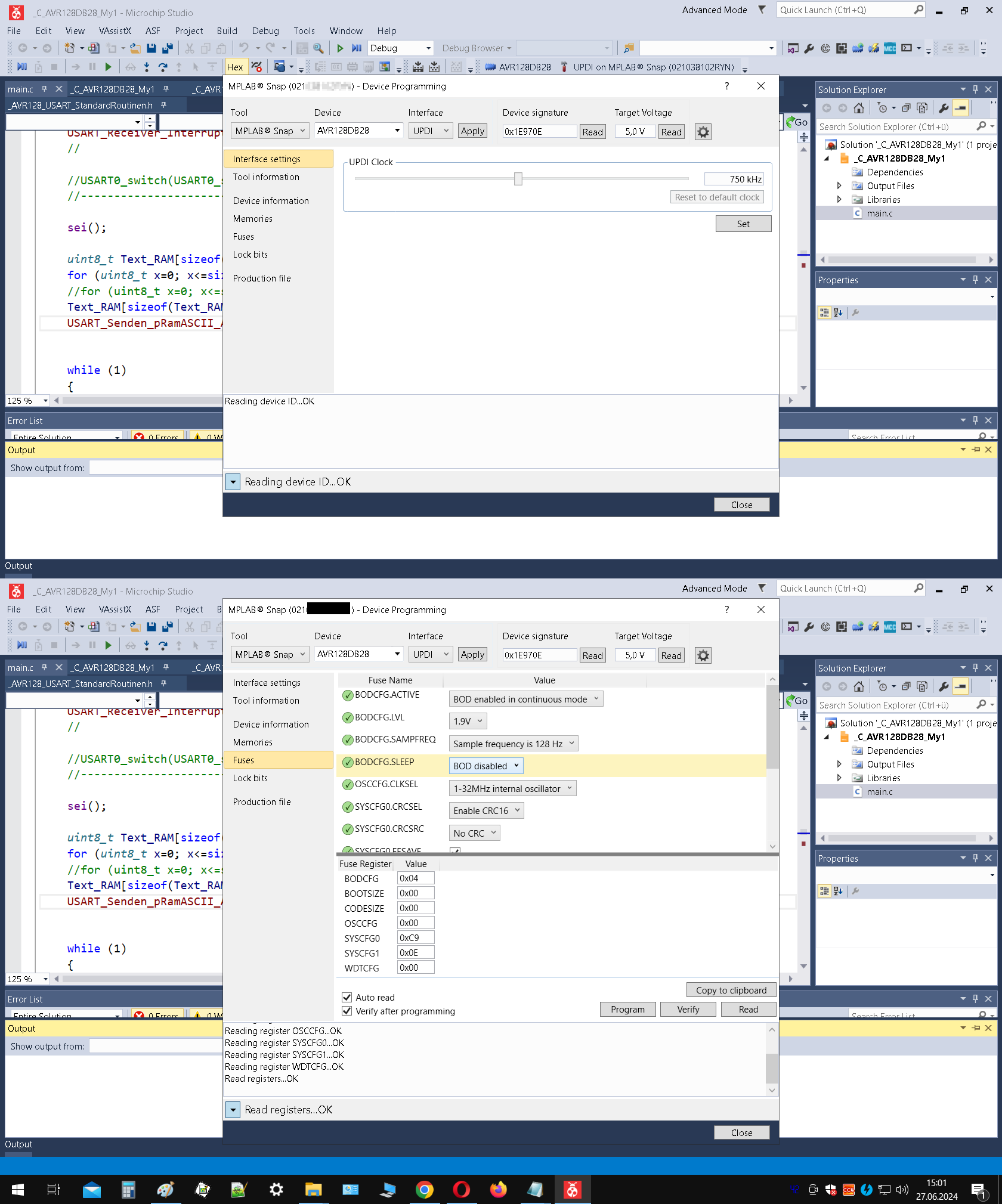
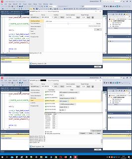
Screenshots der MPLAB Snap Software zur Programmierung
MPLAB Snap, AVR128DB28, Device Programming, Interface settings, Tool information, Fuse Name, Fuses, Device information, Memories, Production file, Lock bits, Target Voltage, Reading device ID... OK
in „MPLAP Snap halb im Nirvana“ · Mikrocontroller und Digitale Elektronik · · Screenshots
-
 Bild
Bild
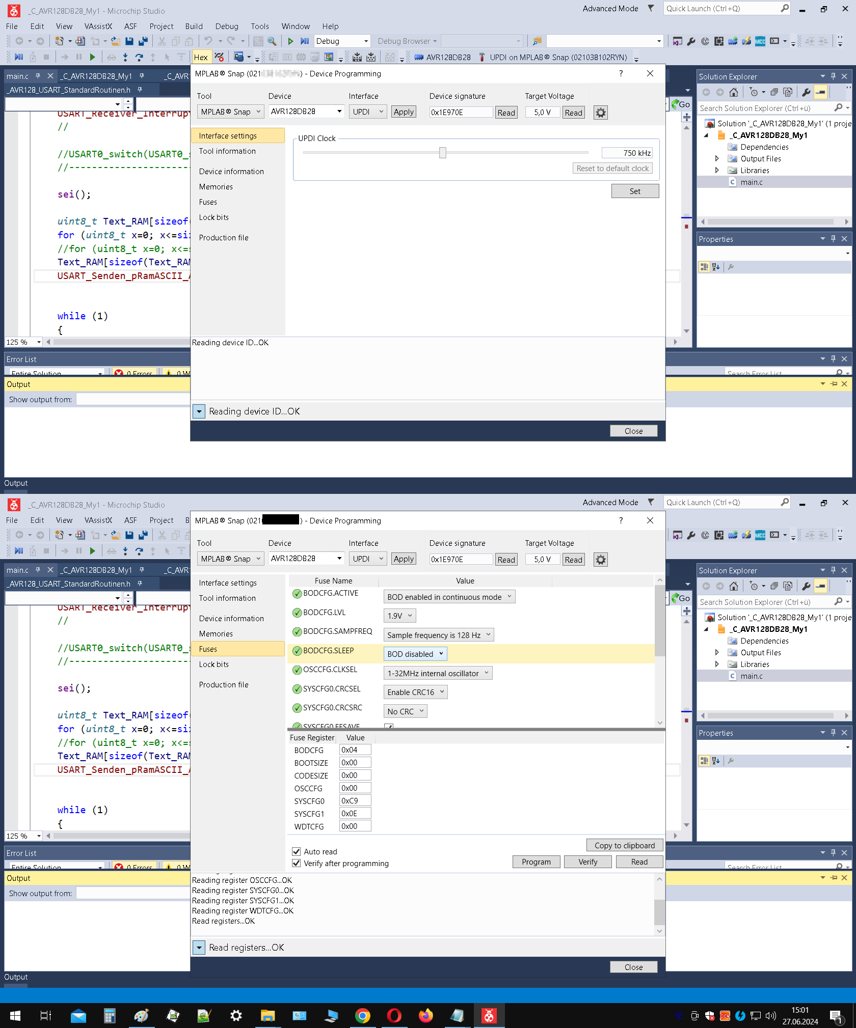
MPLAB Snap Interface Einstellungen
MPLAB Snap, AVR128DB28, Interface settings, Tool information, Device, Interface, Device signature, Target Voltage, UPDI, Apply, 0x19E70E, Read, V, Fuse Name, Fuses, Memories, Production file, Lock bits, Reading device
in „neue AVR-µCs: Entwicklungsumgebung“ · Mikrocontroller und Digitale Elektronik · · Screenshots

-
Datei
grafiklcd.asm
###################### ; ; Name: T6963C Tester ; ; Aufgabe: Testprogramm zur Ansteuerung eines 160x128 Pixel Grafik ; LCDs mit dem Toshiba T6963C Controller ; ; ; Verkabelung: ; ; PortB -> DB0-DB7 = 8 Datenleitungen zum Display ; PortD2 -> CE (active low) ; PortD3 -> C/D (Data=low / Comm=high) ; PortD4
in „Ein paar Fragen zum T6963C“ · Mikrocontroller und Digitale Elektronik ·
-
PDF
Beispiel_Code_KI_generiert.pdf
Annahmen • Ein SSD1306 OLED-Display mit 128x64 Pixel, Ansteuerung per I2C (7-Bit-Adresse meist 0x3C). • Es existieren I2C-Routinen (Start, Write Byte, Stop). • Der AVR-Assembler ist für einen gängigen AVR wie Atmega328P. • 8-Bit-, Registerorientierter Code. Beispiel: Initialisierung der SSD1306 per I2C in AVR- Assembler 1. I2C Basisroutinen (sehr rudimentär/skizzenhaft) /* • i2c_start: • o startet I2C-Kommunikation • i2c_write_byte: • o schreibt ein Byte • i2c_stop: • o stoppt I2C-Kommunikation • • Diese
in „I2C Display einfache Frage“ · Mikrocontroller und Digitale Elektronik ·
-
Datei
m8glcd.asm
;Grafik-LCD 240x128 Pixel im Textmodus mit AT-Mega 8 ;Entwurf... .include"m8def.inc" ;AVR-Definitionen .equ ghome=0 ;Grafik-Home im LCD-Speicher .equ thome=$1700 ;Text-Home im LCD-Speicher .equ garea=30 ;Grafik-Area im
in „Fehlersuche Displaysteuerung“ · Mikrocontroller und Digitale Elektronik ·
-
PDF
doc5131.pdf
Conditions/Notes 11.6.1 Output power P TX 0 3 6 dBm Maximum configurable value 11.6.2 Output power range 20 dB Configurable in register PHY_TX_PWR 11.6.3 Output power tolerance ±3 dB 11.6.4 TX Return loss 10 dB 11.6.5 EVM 8 %rms 11.6.6 Harmonics 2nd harmonic -38 dBm 3rd harmonic -45 dBm 11.6.7 Spurious emissions
-
Datei
macro.asm
.include "AVR128DB28def.inc" .macro put .if @0 < $40 out @0,@1 .else sts @0,@1 .endif .endmacro ;---------------------- .macro puti ldi tmp0,@1 put @0,tmp0 .endmacro ;---------------------- .def tmp0 = r16 puti CPU_CCP
in „AVR DB Serie CLK_OUT“ · Mikrocontroller und Digitale Elektronik ·
-
Datei
mispav.cpp
Bit-Werte mit FC=16 empfangen * @version 2024-04-29 : 32-Bit-Werte mit FC=16 empfangen * weil 8 x 16 = 128 Worte * 4.8.1 C:/WinAVR/bin/avr-g++ -c -I D://h/home/cc/include -I C:/WinAVR/avr/include -gdwarf-2 -mmcu=atmega644p -Wall -Os -DAVR -DNPRGPATH=5 -DF_CPU=16008972UL -DLCD=2 -DLCD_YMAX=4 -DLCD_XMAX=20
in „Implementierung von Menüs auf alphanumerischen Displays“ · Mikrocontroller und Digitale Elektronik ·
-
 Bild
Bild
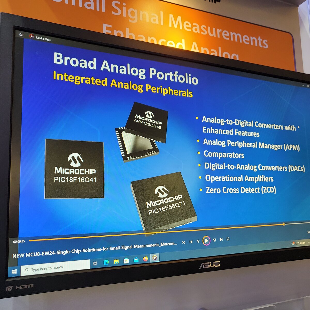
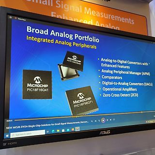
Präsentation von Microchip Analog-Peripheriegeräten auf Monitor
Signal Measurements Enhanced Analog Broad Analog Portfolio Integrated Analog Peripherals MICROCHIP AVR128DB48 Analog-to-Digital Converters with Enhanced Features Analog Peripheral Manager (APM) Comparators Digital-to-Analog Converters (DACs) Operational Amplifiers Zero Cross Detect (ZCD) MICROCHIP PIC18F16Q41
in „Embedded World 2024 - mehr Chips, Software uvam“ · Mikrocontroller und Digitale Elektronik · · Fotos
-
Datei
main_und_ad7305.txt
################################################### main.c #include <avr/io.h> #include "stdlib.h" #include "intern_adc.h" // intern_ADC-Funktionen #include "ad7305.h" // DAC-Funktionen int main(void) { unsigned char sin_table[255] = { 0x7F,0x82,0x85,0x88,0x8B,0x8E, 0x91,0x94,0x97,0x9B
in „8bit DAC an Mega32“ · Mikrocontroller und Digitale Elektronik ·
-
Datei
avr_f64.c
(1l) #endif static char TemporaryMemory[128]; #ifdef USE_AVR #define FLASHMEM_IF_AVR PROGMEM #else #define FLASHMEM_IF_AVR #endif #if defined(USE_AVR) && ( defined(F_WITH_sin) || defined(F_WITH_cos) || defined(F_WITH_tan) || defined(F_WITH_exp
in „64 Bit float Emulator in C, IEEE754 compatibel“ · Projekte & Code ·
-
Datei
avr_f64.c
F_WITH_arctan) || \ defined(F_WITH_to_decimalExp) || defined(F_WITH_to_string)) static char TemporaryMemory[128]; #endif #ifdef USE_AVR #define FLASHMEM_IF_AVR PROGMEM #else #define FLASHMEM_IF_AVR #endif #if defined(USE_AVR) && ( defined(F_WITH_sin) || defined(F_WITH_cos) || defined(F_WITH_tan) || defined(F_WITH_exp
in „64 Bit float Emulator in C, IEEE754 compatibel“ · Projekte & Code ·
-
PDF
doc7627.pdf
8 R12 3 SCK GND 6 PB3 2 SI SO 7 100k RESET 4 RESET VCC 5 3 SCK GND 6 CS WP RESET 4 RESET VCC 5 AT45DB642D CASON8 CS WP AT45DB642D CASON8 2-12 AT90USBKey Hardware User Guide 7627A–AVR–04/06 Using the AT90USBKey 2.5 In-System Programming 2.5.1 Programming with USB bootloader: DFU (Device Firmware Upgrade
in „Problem mit dem TC4469“ · Mikrocontroller und Digitale Elektronik ·