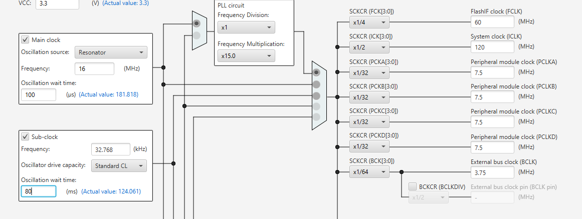
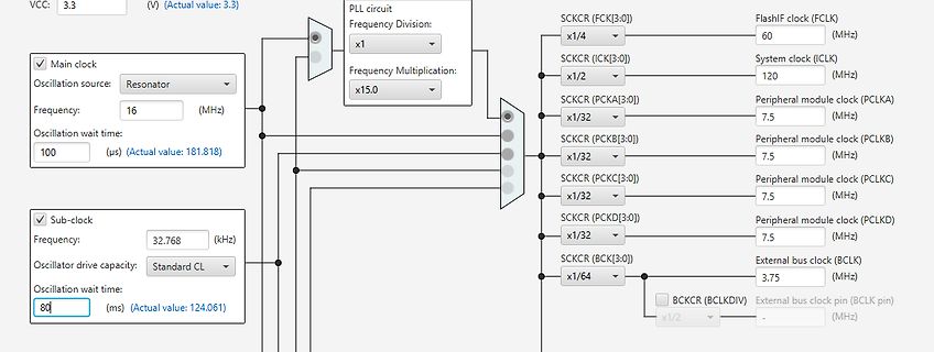
configured to 1MHz Note: 1. Configuration PLL as a clock source, up to 72 MHz, support frequency division 1,2,4,6,8,10,12,16,32, 64,128,256 2. TheAHB_CLK frequency division can be configured as aworking clock up to 72MHz.TheAHB_CLK frequency division can be 1,2,4,6,8,10,12,16,32 3. When switching the
B aus, schalte dann das richtige Segment ein. 2) Der Effekt 1 wird durch die zeitaufwändige Division verstärkt. Berechne den Wert vor der Ausgabe, dann spielt die benötigte Zeit keine Rolle. 3) Die beiden Transistoren, mit denen du die gemeinsamen Anoden bzw. Kathoden der 7-Segment anzeigen ansteuerst
so seine eigene Präferenzen, was das Programmieren angeht, ich persönlich würde aber diese Divisionoperationen komplett rausnehmen bzw. umgehen, indem ich sie durch einfache Addition ersetze. Na wie auch immer – ich bin gespannt wie die nächste Version zusammengewürfelt und -gedichtet wird. CTC für den
RH is advised. N.B. 2: From a computational perspective, in formulae ( 1 ), ( 2 ) and ( 3 ) the division by 2 16− 1 can be simplified to a division by only 2 . The introduced accuracy deviations are <0.002 %RH and <0.003 °C, respectively. 4.7 Serial Number Each sensor has a unique serial number, that
RH is advised. N.B. 2: From a computational perspective, in formulae ( 1 ), ( 2 ) and ( 3 ) the division by 2 16− 1 can be simplified to a division by only 2 . The introduced accuracy deviations are <0.002 %RH and <0.003 °C, respectively. 4.7 Serial Number Each sensor has a unique serial number, that
kompakteren Code. P.S.: Natürlich wurde gegenüber dem STM8 auch auf manches verzichtet, z.B. Divisionsbefehle, Zero-Page-Adressierungsmodus und einige komplexere Adressierungsmodi.
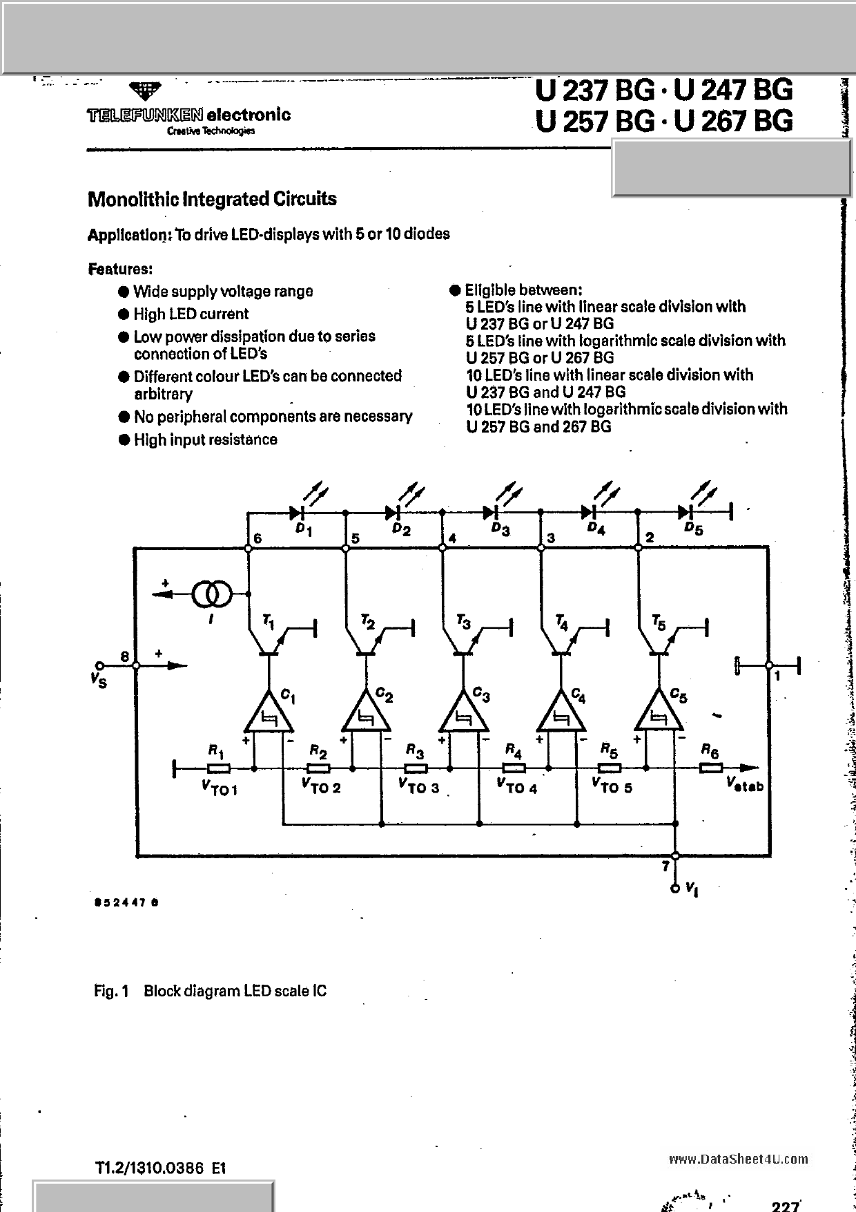
components are necessary
High input resistance
Eligible between:
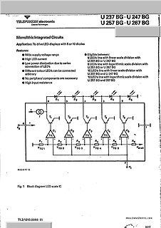
5 LED's line with linear scale division with U 237 BG or U 247 BG
5 LED's line with logarithmic scale division with U 257 BG or U 267 BG
10 LED's line with linear scale division with U 237 BG and U 247 BG
10 LED's line with logarithmic scale division with U 257 BG and 267 BG
Fig. 1 Block diagram LED scale IC
www.DataSheet4U.com
Inrush typA) is also available. Panasonic Industry Co., Ltd. Electromechanical Control Business Division industrial.panasonic.com/ac/e/ ʔ▯▯▯ʔ Panasonic Industry Co., Ltd. 202ASCTB8E 202403 1PXFS▯3FMBZT▯ ▯0WFS▯▯▯"▯ ▯%8▯3&-":4 5:1&4 ˙▯4UBOEBSE▯UZQF▯ ▯▯▯"▯ ˔▯3FqPX▯DPNQBUJCMF▯UZQF 1BSU▯/P▯ 4UBOEBSE▯QBDLJOH
. Oder viel schlimmer noch, Zahlen bis zu 235959, weil du das augenscheinlich ja irgendwie mit Divisionen durch Zehnerpotenzen auf die einzelnen Segmente aufteilen willst. > Habe vor zwei Jahren mit der Programmiersprache C angefangen. Sieh dir an, wie groß der Wertebereich der Datentypen uint8_t
Technology DJ8ES Oscillators Synthesisers Prof. Gisbert Glasmachers 2003/2 107 - 118 Multiplication, division and addition of a 10MHz source to get a Oscillators synthesised VHF signal Andre Jamet, F9HX 2003/2 119 - 124 Miscellaneous Internet Treasure Trove Gunthard Kraus, DG8GB 2003/2 125 - 127 VCXOs with
Internal pull-up voltage V DD 4.3 V VFBto internal current-set point KFB1 V FB= 2V 2.5 2.8 3.1 division ratio VFBto current-set point division KFB2 V FB= 3V 2.8 3.1 3.4 ratio FB level (decreasing) where the regulator enters burst mode V BURL 0.63 0.7 0.77 V FB level (increasing) where the V BURH 0.72
voltage divider action at work, where the ratio of the divider is not constant but changes. FIGURE 2. DIVISION OFVOLTAGEWITHVARIABLE IMPEDANCE SUPPRESSOR However, if the source impedance is very low, then the ratio is low.The suppressor cannot be effective with zero source impedance (Figure 2) and works best
umzugehen. Bin aber nicht ganz sicher, ob ich es heute noch in vollem Umfang könnte. Multiplikation/Division sicher ja. Aber schon beim Quadratwurzelziehen müsste ich wohl erstmal nachdenken, damit ich den richtigen Bereich der mehrdeutigen Abbildung erwische. Nö, da nehme ich lieber das Taschenrechner-Programm
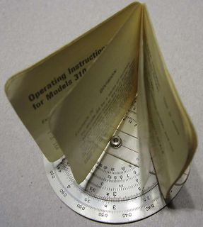
sich das jeder leisten, aber es war verboten. 3/4 der Zeit in einer Klassenarbeit waren manuelle Divisionen und Multiplikationen mit Kommazahlen und entsprechender Fehlerhäufigkeit. Im Gegensatz zu Taschenrechnern waren Rechenschieber aber immer erlaubt. Also habe ich mir das selbst beigebracht was mich
ganze wesentlich > schneller und kleiner, Nicht automatisch, z.B. auf ATmega328: uint32_t Division: ca. 615 Cycles float Division: weniger als 500 Cycles
Johann L. schrieb im Beitrag #7671868: > Nicht automatisch, z.B. auf ATmega328: > > uint32_t Division: ca. 615 Cycles > float Division: weniger als 500 Cycles und was ist mit flash und sram Verbrauch, manchmal ist es nicht die Geschwindigkeit die bremst, sondern das der SRAM ausgeht oder weniger
Andreas M. schrieb im Beitrag #7663911: > Die M0+ kann nicht mal Division in Hardware. Mein rp2040 kann's. Je einmal pro core. In acht Takten.
definitiv mehr als genug Rechenleistung für den Job. > > Nein hat er nicht. Die M0+ kann nicht mal Division in Hardware. Der Bezug war klar erkennbar der RP2040.
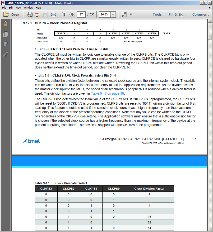
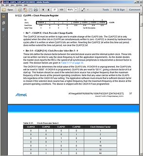
the master clock input to the MCU, the speed of all synchronous peripherals is reduced when a division factor is used. The division factors are given in Table 9-16 on page 49. The CKDIV8 Fuse determines the initial value of the CLKPS bits. If CKDIV8 is unprogrammed, the CLKPS bits will be reset to
Note: The MeasuredSpeed Calculation is made in assembly to take advantage of the signed fractional division. ********************************************************************/ void __attribute__((interrupt, no_auto_psv)) _T1Interrupt (void) { IFS0bits.T1IF = 0; Period = ActualCapture - PastCapture; /
CRC: cyclic redundancy check (remainder of a etc., and the consequences of electrical/mechanical division calculation). All devices that pass the CRC failure modes in the wiring. All these aspects are treated will acknowledge or will generate an error flag seriously by the CAN specifications and the suppliers
3 2 1 0 PDIV[3:0] PEN Access R/W R/W R/W R/W R/W Reset 0 0 0 0 0 Bits 4:1 – PDIV[3:0] Prescaler Division If the Prescaler Enable (PEN) bit is written to ‘1’, this bit field defines the division ratio of the main clock prescaler. This bit field can be written during run-time to vary the clock frequency
should have execute permission for everything in /sbin that can be executed by non-root users. The division between /bin and /sbin was not created for security reasons or to prevent users from seeing the OS, but to provide a good division between binaries that everyone uses and the ones that are primarily
selbst erklärten Anfänger wie dem TO einfachre einen Shift zu programmieren (">>") als ein korrekte Division durch 10.0. Zumal dafür der Sensorwert erstmal in eine korrekte (normalisierte) float zu konvertieren ist.
>> Division durch 10.0. > > Lies nochmal. Der TO hat gar nicht nach der Berechnung von 10 % gefragt, Doch, hat er. >> wenn sich der aktuelle Messwert vom letzten Messwert nicht mehr als 10% >> unterscheidet
aktuelles "Funkwetter" über WWV 10MHz zu Minute 18. https://www.nist.gov/pml/time-and-frequency-division/time-distribution/radio-station-wwv/wwv-and-wwvh-digital-time-code Und PTB misst auch: https://www.ptb.de/cms/nc/ptb/fachabteilungen/abt2/fb-25/ag-251/live-daten-erdmagnetfeldmessung.html ciao
connections, because of variations in the circulation resistances of units, the correct voltage division between capacitors should be ensuredbyresistivevoltagedividers.Theinsulationvoltageofthesingleunitsshallbeappropriatefortheseriesarrangement.Theabovemustbe takeninconsiderationwhensubmittingequipmenttoover-voltageorover-loadtestsandevaluatingpotentialequipmentmalfunctionsorfailure
DD1.1 and DD1.2 CD4093 chip and the DA1 222 chip. At an input signal frequency of 100 kHz, the division coefficient set by the potentiometer R1 can take the values 1, 2, 3 ... 20. Figure 27: Another version of the single-vibrator. The duration of the output signals of single- vibrators (Fig.25-27) depends
pressing for an earlier ban on these substances. TEMIC TELEFUNKEN microelectronic GmbH semiconductor division has been able to use its policy of continuous improvements to eliminate the use of ODSs listed in the following documents. 1. Annex A, B and list of transitional substances of the Montreal Protocol
pressing for an earlier ban on these substances. TEMIC TELEFUNKEN microelectronic GmbH semiconductor division has been able to use its policy of continuous improvements to eliminate the use of ODSs listed in the following documents. 1. Annex A, B and list of transitional substances of the Montreal Protocol
eine Folge von (1 000 000 Werten pro Sekunde) x (10 Millisekunden) = 10 000 Werte geliefert. Die Division durch die Zahl 10 vermindert die Maximalamplitude von +-0,5V auf einen praxisgerechteren Wert von +-50 Millivolt und liefert folgendes für die gewählte Sweep-Einstellung folgendes Ergebnis: Bitte
Clock and Frame Sync Signals for Each Receiver and Transmitter – I²S Analog Interface Support, Time Division Multiplex Support – High-speed Continuous Data Stream Capabilities with 32-bit Data Transfer ! One Two-wire Interface (TWI) – Master Mode Support Only, All Two-wire Atmel EEPROMs Supported ! Multimedia
Das grundlegende Problem ist die Umwandlung 2er Kompl. zu 10er komplement). Dies möglichst ohne division oder mudulo. Selbst Multiplikationen sind zeitintensiv - da all diese operationen von der CPU nicht nativ unterstüzt.
Modellen unterschiedlicher Hersteller angeschaut. Bei allen ist es wie du sagst eine schlichte Division. Aber man beachte die Beschriftung "junction-to-ambient" (Umgebung, nicht Anschlussfahne). Die Kühlung durch die Platine in 25°C Luft ist da schon mit drin! Bei den größeren TO220 Modellen steht
Register (F0H) Das B-Register muss in Verbindung mit dem Akkumulator A bei Multiplikations- und Divisionsoperationen verwendet werden. Der Multiplikationsbefehl MUL A, B kombiniert die 8 Bits im Akkumulator A und im Register B. Vorzeichenbehaftete Zahlen werden multipliziert und das niederwertige Byte des resultierenden 16-Bit-Produkts wird in A und das höherwertige Byte in B platziert. Die Divisionsanweisungen DIV A und B dienen dazu, A durch B zu dividieren. Der Quotient wird in A und der Rest in B abgelegt. Register B kann auch als allgemeines temporäres Register verwendet werden. Stapelzeiger SP
noch mehr Anwendungsfälle abdecken“, sagt Patrick Aidoune, General Manager der General Purpose MCU Division von STMicroelectronics. „Mit ihren MPU-ähnlichen Qualitäten erzielen die Produkte eine herausragende Core-Performance, verbunden mit der Peripherieintegration und dem Komfort eines Mikrocontrollers
D5h A[7:4]. The display clock (DCLK) for the Display Timing Generator is derived from CLK. The division factor “D” can be programmed from 1 to 16 by command D5h DCLK = F OSC / D The frame frequency of display is determined by the following formula. F osc F FRM = D×K× No.of Mux where • D stands for clock

 Bild
Bild
 Bild
Bild

 Bild
Bild

 Bild
Bild

 Bild
Bild
 Bild
Bild
 Bild
Bild
 Bild
Bild
 Bild
Bild
 Bild
Bild