-
Bild
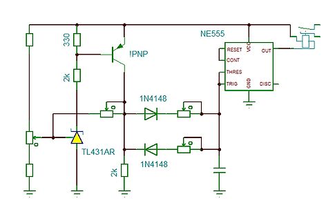
Schaltplan mit NE555, PNP-Transistor und TL431AR
330 2k IPNP NE555 RESET VCQ OUT CONT THRES TRIG GND DISC 1N418 1N418 TL431AR 2k
in „Schaltbild für D+-Signal-Simulator“ · Analoge Elektronik und Schaltungstechnik · · Schaltpläne
-
PDF
DLO2416.pdf
don’t car= all dots on DLR/DLO/DLG2416 5–3 Loading Data Figure 3. DLX2416—Flashing circuit using a 555 Setting the chip enable (CE1, CE2) to their true state will enable and Flashing (Blanking) timing data loading. The desired data code (D0-D6) and digit address VCC =5.0 V (A0, A1) must be held stable
-
Datei
Tabelle-Wegpunkte.txt
269,29.333,106.981 270,27.578,104.548 271,25.822,102.116 272,24.067,99.683 273,22.311,97.250 274,20.555,94.818 275,18.800,92.385 276,17.044,89.952 277,15.289,87.520 278,13.533,85.087 279,11.778,82.654 280,10.022,80.222 281,8.266,77.789 282,6.531,75.342 283,4.914,72.817 284,3.483,70.182 285,2.300,67.427
-
PDF
Quasimodo_jig_revA.pdf
that Quasimodo will correctly operate at supply voltages below 2.7V. The 120Hz oscillator uses a CMOS 555 with rail-to-rail output swing, for the same reason: a non-CMOS 555 chip’s output only swings to VCC – 2VBE, which spoils low voltage operation. Injection capacitor C2 is socketed, with provision for
in „Stromversorgung Extra Kondensatoren“ · Analoge Elektronik und Schaltungstechnik ·
-
Bild
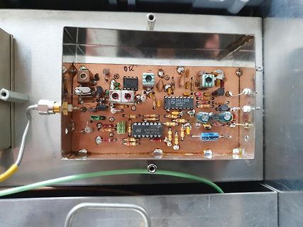
Foto einer Leiterplatte in einem Metallgehäuse
SA614AN LM324N MALAYSIA 103
in „Verkaufe Amateurfunk TX/RX 2.4 GHz (13 cm) für Packet Radio“ · Markt · · Platinenfotos
-
PDF
thermistor.pdf
electrical 6812’s built-in 8-bit 5-V ADC P 3 Reset 5 V power below 0.05 mW. Therefore, the PT6 OUT Out TLC555 8 has a resolution of: 5 Cont VDD current had to be below: 0.1µF 1 0.1µF Gnd (19) (16) Figure6—Thiscircuitconvertsthermistorresistancetoperiod.As thethermistorresistancevariesfrom198.3to551.2kilohms
in „regelbare Konstantstromquelle“ · Mikrocontroller und Digitale Elektronik ·
-
PDF
DLx2416.pdf
= all dots on 2006-01-23 7 DLR2416, DLO2416, DLG2416 Loading Data DLX2416—Flashing Circuit Using a 555 and Flashing (Blanking) Timing Setting the chip enable (CE1, CE2) to their true state will enable data loading. The desired data code (D0-D6) and VCC =5V digit address (A0, A1) must be held stable during
in „(V) 4-Fach 5*7 Punktmatrix Osram DLR 2416, Bistabile Relais SDS, LED-Display 7-Seg. 4-Fach“ · Markt ·
-
PDF
an-978.pdf
the low operating current requirement of the IR2125, the charge pump employs a CMOS version of the 555 timer. 9 VDD VB 6 IGBT HV +15 V IRFD IRFD9110MODULE(S) 9110 + 10 µF HO 7 100 IR2110 µF1 + IRFD CF + 5 110 IRFD110 100 µF VS VCC 3 HIN 10HIN IRFD9110 IRFD9110 IGBT TO + MODULE(S) LOAD 11 10 µF LIN SD
in „Treiber-IC Peripherie berechnen“ · Mikrocontroller und Digitale Elektronik ·
-
PDF
an-978.pdf
the low operating current requirement of the IR2125, the charge pump employs a CMOS version of the 555 timer. 9 6 VDD VB IRFD IGBT HV +15 V 9110 IRFD9110MODULE(S) + 10 µF 7 HO 100 0.1 IR2110 µF + CF + IRFD IRFD110 100 µF VS 5 110 3 10 VCC IRFD9110 IRFD9110 IGBT TO HIN HIN MODULE(S) LOAD + LIN 11SD 10
in „Isolierter High-Side Mosfet Treiber“ · Analoge Elektronik und Schaltungstechnik ·
-
PDF
ir2110-app-note.pdf
the low operating current requirement of the IR2125, the charge pump employs a CMOS version of the 555 timer. 9 6 VDD VB IRFD IGBT HV +15 V 9110 IRFD9110MODULE(S) + 10 µF 7 HO 100 0.1 IR2110 µF + CF + IRFD IRFD110 100 µF VS 5 110 3 10 VCC IRFD9110 IRFD9110 IGBT TO HIN HIN MODULE(S) LOAD + LIN 11SD 10
in „[Transistor Ansteuerung] Ausgang kein Rechteck?“ · Analoge Elektronik und Schaltungstechnik ·
-
PDF
an-978.pdf
the low operating current requirement of the IR2125, the charge pump employs a CMOS version of the 555 timer. 9 6 VDD VB IRFD IGBT HV +15 V 9110 IRFD9110MODULE(S) + 10 µF 7 HO 100 0.1 IR2110 µF + CF + IRFD IRFD110 100 µF VS 5 110 3 10 VCC IRFD9110 IRFD9110 IGBT TO HIN HIN MODULE(S) LOAD + LIN 11SD 10
in „high-side gate driver mit LT-Spice simulieren“ · Analoge Elektronik und Schaltungstechnik ·
-
PDF
an-978.pdf
the low operating current requirement of the IR2125, the charge pump employs a CMOS version of the 555 timer. 9 6 VDD VB IRFD IGBT HV +15 V 9110 IRFD9110MODULE(S) + 10 µF 7 HO 100 0.1 IR2110 µF + CF + IRFD IRFD110 100 µF VS 5 110 3 10 VCC IRFD9110 IRFD9110 IGBT TO HIN HIN MODULE(S) LOAD + LIN 11SD 10
in „Halbbrücke Gate-Treiber Erklärung“ · Analoge Elektronik und Schaltungstechnik ·
-
PDF
an-978.pdf
the low operating current requirement of the IR2125, the charge pump employs a CMOS version of the 555 timer. 9 6 VDD VB IRFD IGBT HV +15 V 9110 IRFD9110MODULE(S) + 10 µF 7 HO 100 0.1 IR2110 µF + CF + IRFD IRFD110 100 µF VS 5 110 3 10 VCC IRFD9110 IRFD9110 IGBT TO HIN HIN MODULE(S) LOAD + LIN 11SD 10
in „H-Brücke mit 100% Duty-Cycle“ · Analoge Elektronik und Schaltungstechnik ·
-
Datei
sinustab.txt
98,100,101 db 103,104,106,107,109,110,112,113,115,117,118,120,121,123,124,126 512,518,524,530,537,543,549,555,562,568,574,580,587,593,599,605, 611,617,624,630,636,642,648,654,660,666,672,678,684,690,696,701, 707,713,719,725,730,736,741,747,753,758,764,769,774,780,785,790, 796,801,806,811,816,821,826,831,836,841,846,850,855,860,864,869
in „DDS normal ?“ · Mikrocontroller und Digitale Elektronik ·
-
Datei
mess.txt
61.549 64.717 -- -- 548 0.063800 61.879 61.615 -- -- 549 0.063900 63.067 64.717 -- -- 550 0.064000 67.555 70.195 -- -- 551 0.064100 69.733 70.954 -- -- 552 0.064200 71.747 65.839 -- -- 553 0.064300 75.608 75.443 -- -- 554 0.064400 74.486 74.981 -- -- 555 0.064500 64.717 67.456 -- -- 556 0.064600 67.225
in „Diagramm aus txt-File vs. Excel 2003“ · Softwareentwicklung ·
-
Datei
fy.html
0; } </style> </head> <body> <h1>FY6900 Web Steuerung v9</h1> <p style="font-size: 0.8em; color: #555;">Frequenzbefehl in µHz (Hz*10⁶), Sweep Cmd = Hz.x<br>Benötigt Chrome/Edge & CH340/FY6900 Treiber.</p> <div class="control-group"> <h3>Verbindung</h3> <button id="connectButton" class="action-button
in „FY6900 Funktionsgenerator Software erstellt“ · Projekte & Code ·
-
PDF
Weidezaun_S03_4093.pdf
2 1000V 1A M0207 1 Rohr-PVC D316/250mm Wand6,5mm x 9 TL750L12CLP TO92 LDO Uin26V 1mA 150mA u m BCR555 2k2+10k 50V 500mA hfe70 1,4Von 0,4Voff SOT23 12S6640 0,06€/100 SOT23 Inf 6 V LM317 TO92 (1k2+11k 0805) O A C7 PDTA143ZT,215 4k7+47k 50V 0,1A hfe100 0,9Von 0,6Voff 250mW Ali 2,74€/50 Nexperia 7 0 3 nc1k2
in „Weidezaun gegen Schnecken mit Netztrafo und Rohr DN160 für Hobbygärtner“ · Projekte & Code ·
-
Datei
mtvc.pl
>Button(-text => "Download", -command=>\&connect_download); $connbutton->place(-x => "50" , -y => "555"); my $uploadbutton = $main->Button(-text => "Upload", -command=>\&upload_files); $uploadbutton->place(-x => "250" , -y => "555"); my $storebutton = $main->Button(-text => "Änderungen speichern", -command=>\&patch_files); $storebutton->place(-x => "420" , -y => "555"); my $testbutton = $main->Button(-text => "neuer Ordner", -command=>\&create_folder); $testbutton->place(-x => "620" , -y => "555"); #callback's sub tree_command { #bei doppelklick auf einen treeeintrag
in „Pollin - Receiver-Mainboard mit Twin DVB-[T,C] Tuner, NXP PNX8950EH“ · Mikrocontroller und Digitale Elektronik ·
-
Datei
strace.txt
1CEST,M3.5.0,M10.5.0/3\n", 4096) = 28 close(5) = 0 write(4, "lease {\n interface \"enp1s0\";\n "..., 555) = 555 getpid() = 406 clone(child_stack=NULL, flags=CLONE_CHILD_CLEARTID|CLONE_CHILD_SETTID|SIGCHLD, child_tidptr=0xb70fa768) = 407 wait4(-1, [{WIFEXITED(s) && WEXITSTATUS(s) == 0}], 0, NULL) = 407
-
PDF
tcrt5000_application_note.pdf
K 33 k 33 k 7 2 DIS RQ 3 1 ▯F 6 RB 6 3 Output 5.1 k THR TLC 271 2 TR CV 5 (CA3160) GND RE R 1 Cq 4 555 C 1 510 1 k 22 nF 100 nF 100 nF GND GND Timer dimensions: p (pulse width) = 0.8 RC = 400 ▯s T (period) = 0.8 (A + B )▯ C = 1 ms Cq Active filter : C ▯ ▯C fC q Q ▯ ▯ Cf f ▯ 1▯(6.28 ▯ C ▯ R) V ▯ 2 R ▯
in „Alten Stromzähler elektronisch auslesen“ · Mikrocontroller und Digitale Elektronik ·
-
PDF
Weidezaun_S03_4093.pdf
2 1000V 1A M0207 1 Rohr-PVC D316/250mm Wand6,5mm x 9 TL750L12CLP TO92 LDO Uin26V 1mA 150mA u m BCR555 2k2+10k 50V 500mA hfe70 1,4Von 0,4Voff SOT23 12S6640 0,06€/100 SOT23 Inf 6 V LM317 TO92 (1k2+11k 0805) O A C7 PDTA143ZT,215 4k7+47k 50V 0,1A hfe100 0,9Von 0,6Voff 250mW Ali 2,74€/50 Nexperia 7 0 3 nc1k2
in „Weidezaun gegen Schnecken mit Netztrafo und Rohr DN160 für Hobbygärtner“ · Projekte & Code ·
-
PDF
TSL220.PDF
BI BI BI BI 14 8 14 8 14 8 14 8 14 8 5 5 V 5 V to to t LS 8 4 16 3 120 K t 22 K 7 3 LS 15 4 Q 1 K NE555 100 pF SN74123 6 14 2 2 1 2.2 F 8 1 Figure 14. Simple Digital Light Meter V CC 3 Port or 6 Interrupt 2 Input OUT P C TSL220 4 5 Figure 15. Light Detector with Direct Microprocessor Interface POST OFFICE
in „timer 2 interrupt?“ · Mikrocontroller und Digitale Elektronik ·
-
Datei
display.asm
19 Hz wäre es max.ungenauer z104: .db $00,$00,$30,00 ;3 Byte accustep Maxwert entspricht 104167 Hz z555: .db $23,$7A,$08,00 ;Konstante für die Frequenzausgabe = 5e6/9 ;Genauigkeit Byterichtung low zuerst z10k: .db $a6,$9B,$04,00 ;4e-7 ;lo-Byte zuerst!! z1k: .db $f7,$75,$00,00 ;4e-7 z100: .db $cc,$0b,$00,00
in „LCD Routine Funktioniert nicht“ · Mikrocontroller und Digitale Elektronik ·
-
PDF
Microwave_Oven_Inverter_HV_Power_Supply.pdf
the final use to which the HV Inverter supply is intended). A simple PWM generator was built using a 555. Details may be found in the 555 datasheet. The potentiometer that varies the duty cycle has fixed resistors at each end to limit the adjustment to within the 25% to 75% to range generated by the microwave
in „Mikrowelle mit weniger als 700 (Nenn-)Watt gesucht__Wieviel gemessene Watt benötigt Eure Mikrowelle?“ · Haus & Smart Home ·
-
PDF
Vergleichsliste.pdf
ECG82 2N3352 BFX36 2N5796 2N4024 ECG83 TD-102 ECG85 2SC2002 2SC1741 ECG86 2SC1768 2SC1829 ECG87 2SD555 2SD997 ECG88 2SB600 2SB796 ECG89 2SD903 2SD1175 2SD1016 2SD870 2SD871 BU208D ECG90 2SD756 2SD667A 2SC1900 2SC2363 2SC3329 2SC1673 ECG91 2SB716 2SB647A ECG92 2SC2773 2SC2774 ECG93 2SA1170 ECG94 2SC1114
in „ECG45 was ist das?“ · Analoge Elektronik und Schaltungstechnik ·
-
Bild
-
Bild
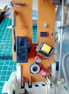
Nahaufnahme einer Leiterplatte mit Bauteilen
DN, NE555, 2207M, DN
in „Bauteil mit goldener Kugel?“ · Analoge Elektronik und Schaltungstechnik · · Platinenfotos
-
Bild
Lautsprecher in Kunststoffgehäuse mit Kabeln
141-11 4A 03M 555A
in „[B]iete Mitbestellmöglichkeit Mouser & LCSC“ · Markt · · Fotos
-
Bild
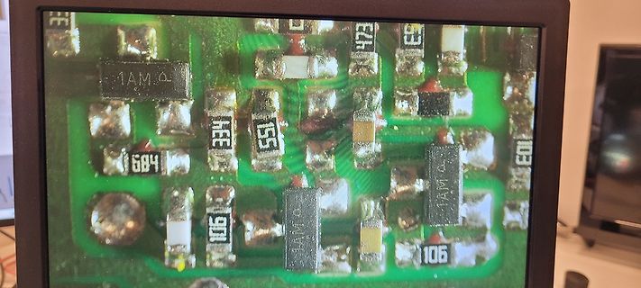
Foto einer bestückten Leiterplatte auf einem Bildschirm
1AM Ω, 334, 555, 684, 106, 1AM Ω, 106
in „Intertechno ITL 3500 defekt“ · Analoge Elektronik und Schaltungstechnik · · Fotos
-
Bild
Multimeter misst Spannung an einer Leiterplatte
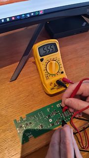
555 600 200 V 200m 200 200 200
in „Bosch Induktionsherd geht nicht mehr“ · Haus & Smart Home · · Platinenfotos
-
PDF
Schaltplan.pdf
?????? Motor minus NE555P LC7812CV Buchse auf Platine
in „PWM Umbau für SPS-Ansteuerung“ · Mikrocontroller und Digitale Elektronik ·
-
Bild
Zeiss Ikon Schloss, Schlüssel und Verpackung
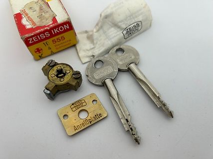
ZEISS IKON 10 555 4 Werkhöhe Schlüsselloch ZEISS IKON ZEISS IKON Anreißplatte
in „Ratespiel Röhrengerät, groß aber tragbar, Vorkriegsmodell“ · Analoge Elektronik und Schaltungstechnik · · Fotos
-
Bild
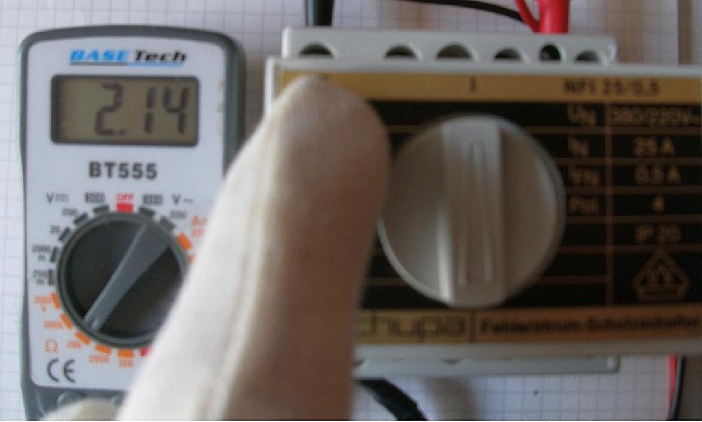
Multimeter und FI-Schutzschalter Messaufbau
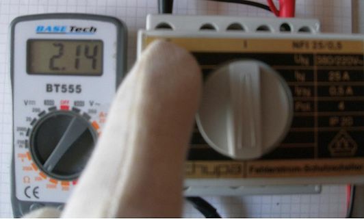
BASE Tech 2.14 BT555 NFI 25/0,5 IP 20
in „FI-Schalter AC oder nur A?“ · Haus & Smart Home · · Fotos
-
Bild
Elektronikbauteile und Komponenten auf weißem Papier
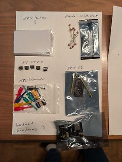
NFC-Karten? Photo - Videostunde NE 555 P STM 32 Messklemmen Breadboard Einspeisung
in „Wanderkiste Widlar VII“ · Markt · · Fotos
-
Bild
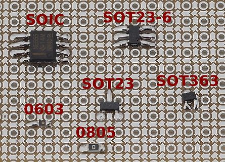
Verschiedene SMD-Bauteilgehäuse auf einer Leiterplatte
SOIC SOT23-6 NE555 NM40 0603 SOT23 SOT363 0805
in „Lochrasterplatine für 2,54mm und 1,27mm Raster“ · Platinen · · Platinenfotos
-
Bild
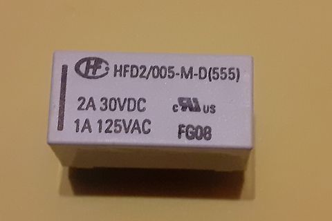
Relais mit Typenbezeichnung
HFD2/005-M-D(555) 2A 30VDC 1A 125VAC FG08
in „# Was ist das für ein Relais HFD2/005-M-D(555) ?“ · Analoge Elektronik und Schaltungstechnik · · Fotos
-
Bild
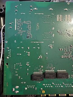
Leiterplatte mit integrierten Schaltkreisen
LG2414TSN 1652C LG2414TSN 1652C LG2414TSN 1652C 5.40 555.216
in „FritzBox 7490 defekt“ · PC Hard- und Software · · Platinenfotos
-
Bild
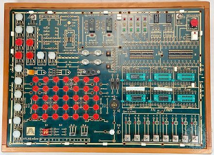
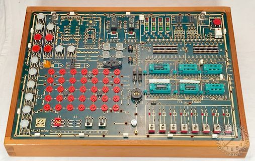
Atlas Micro Praxis-Trainer Lernplatine
OP-V./TIMER, U0=DC+15V, LM741/NE 555, IMPULSGEBER, TTL u. CMOS, ATLAS micro PRAXIS-TRAINER
in „[V] ATLAS micro Praxis Trainer“ · Markt · · Platinenfotos
-
Bild
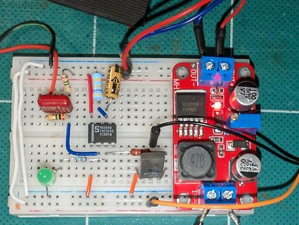
Aufbau auf Breadboard mit Spannungsregler-Modul
NE555P PKF3906 9135VM XL6019-1 919W 50V 100 470 220 35V VT
in „Licht durch eine kleine LED schalten“ · Analoge Elektronik und Schaltungstechnik · · Fotos
-
Bild
Elektronik-Trainingsmodul Atlas Micro Praxis-Trainer auf Holzbrett
OP-V/TIMER, IMPULSGÄBER, LM741/NE555, TO 220, MODULE, 15 V DC, TTL u. CMOS, ATLAS micro PRAXIS-TRAINER
in „[V] ATLAS micro Praxis Trainer“ · Markt · · Platinenfotos
-
Bild
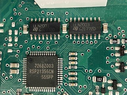
Nahaufnahme einer Leiterplatte mit integrierten Schaltkreisen
ULN2003 GZE7720 ULN2003 GZE7720 726BZ003 R5F21356CN 555FP 101 102 201
in „Backofen Siemens IQ500“ · Haus & Smart Home · · Platinenfotos
-
Bild
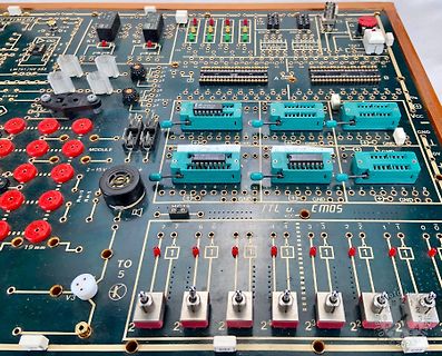
Bestückte grüne Leiterplatte mit IC-Sockeln und Schaltern
TIMER, LM741/NE555, K1, K2, K3, DUAL, DUAL, TACT, MODULE, 2-15V, GND, TTL, CMOS, VCC, V3
in „[V] ATLAS micro Praxis Trainer“ · Markt · · Platinenfotos
-
Bild
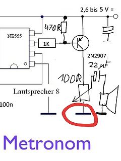
Handgezeichneter Schaltplan eines Metronoms
NE555 1K 470R 2,6 bis 5 V = 2N2907 22µF 100R Lautsprecher 8 100n Metronom
in „Metronom mit Ne555“ · Analoge Elektronik und Schaltungstechnik · · Schaltpläne
-
Bild
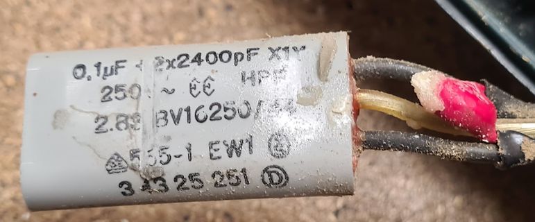
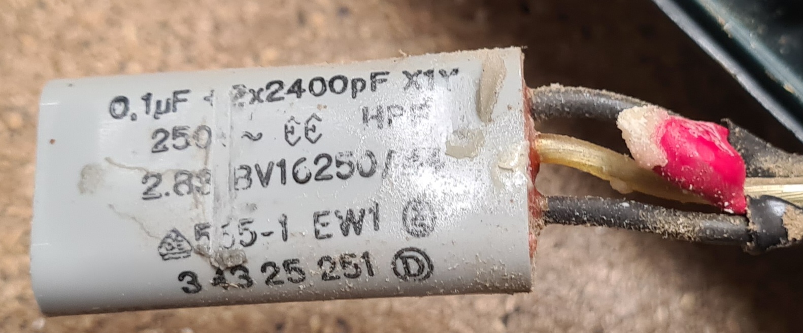
Kondensator mit Beschriftung
0,1µF 2x2400pF X1Y 250 ~ Æ HP 2.89 BV16250 555-1 EW1 3 43 25 251
in „Metabo Sr e 285 Kondensator“ · Mechanik, Gehäuse, Werkzeug · · Fotos
-
Bild
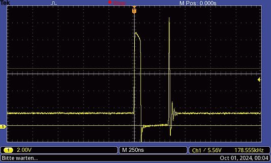
Oszilloskop-Messkurve eines Spannungsimpulses
Tek M Pos: 0.000s 1 2.00V M 250ns Ch1 / 5.56V 178.555kHz Bitte warten... Oct 01, 2024, 00:04
in „Neulich aus der Reparaturpraxis“ · Analoge Elektronik und Schaltungstechnik · · Oszi-Bilder
-
Bild
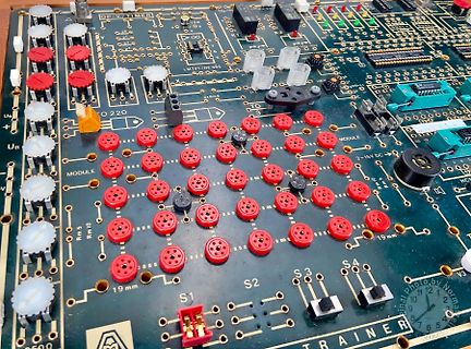
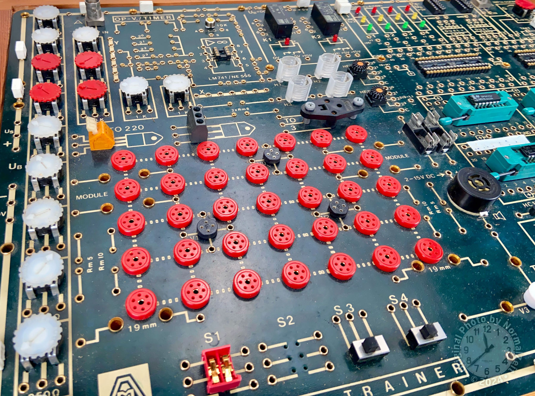
Detailaufnahme einer bestückten Leiterplatte eines Trainers
OP-V/TIMER, LM741, NE 555, 2x47kΩ, 2-15V DC, MODULE, Rm 5, Rm 10, 19 mm, S1, S2, S3, S4, TRAINER
in „[V] ATLAS micro Praxis Trainer“ · Markt · · Platinenfotos
-
Bild
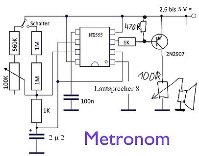
Handgezeichneter Schaltplan eines Metronoms
Schalter 560K 1M 100K 1M 1K 2 µF 100n NE555 1K 470 R 2,6 bis 5 V 2N2907 100R Lautsprecher 8 Metronom
in „Metronom mit Ne555“ · Analoge Elektronik und Schaltungstechnik · · Schaltpläne
-
Bild
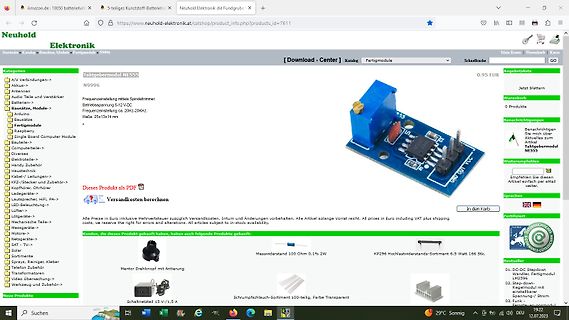
Webseite eines Elektronik-Onlineshops
amazon.de; Neuhold Elektronik; Taktgebermodul NE555; N9996; 0,95 EUR; Warenkorb; Versandkosten berechnen; Messwiderstand 100 Ohm 0,1% 2W; Mentor Drehknopf mit Arbeitierung; Schrumpfschlauch-Sortiment 100-teilig; Schaltnetzteil 15 V / 1,5 A
in „Physikprojekte“ · Offtopic · · Screenshots
-
Bild
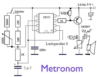
Handgezeichneter Schaltplan eines Metronoms
Schalter 560K 1M 100K 1M 1K 2 µ 2 100n NE555 1K 470 R 2,6 bis 5 V 2N2907 22 µF 100R Lautsprecher 8 Metronom
in „Metronom mit Ne555“ · Analoge Elektronik und Schaltungstechnik · · Schaltpläne
-
Bild
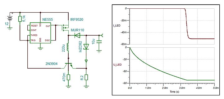
Schaltplan und Oszilloskop-Messkurven einer LED-Schaltung
12, 5,1k, NE555, IRF9520, OUT, VCC, RESET, CONT, THRES, TRIG, GND, DISC, 220u, MUR110, 10u, MZD82, 2N3904, 470m, 8,2, L_LED, U_LED, Time (s)
in „5V-12V auf ca 60-80V 50mA“ · Analoge Elektronik und Schaltungstechnik · · Schaltpläne