-
PDF
AN735.pdf
retrieve one byte banksel temp_hold ; select GPR bank movwf temp_hold ; save off byte 1 movf ptr2,w DS00735A-page 18 Preliminary 2000 Microchip Technology Inc. AN735 movwf FSR ; init FSR movf INDF,w ; retrieve second byte subwf temp_hold,f ; do comparison btfss STATUS,Z ; test for valid compare goto
in „I2C example code“ · Mikrocontroller und Digitale Elektronik ·
-
 Bild
Bild
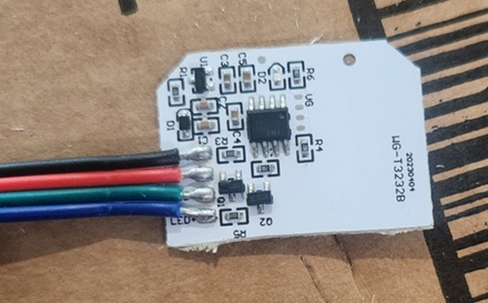
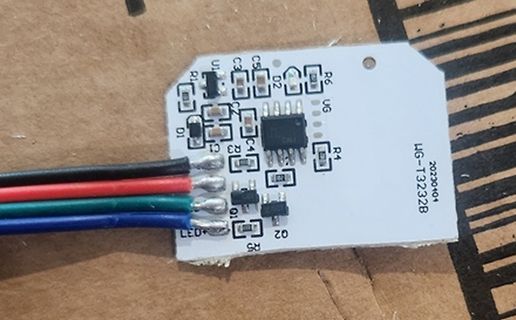
Kleine Leiterplatte mit Kabeln und SMD-Bauteilen
U1, C3, C5, D2, R6, U6, R4, R3, C4, C2, D1, R1, Q1, Q2, R5, UG-T3232B
in „ESP8266 mit Berührungssensor“ · Mikrocontroller und Digitale Elektronik · · Platinenfotos
-
Datei
DS18S20.asm
rcall print1 ret ;****************************************************************************** ;ds18s20 routinen ;****************************************************************************** reset_pulse: sbi ddrb, 0 ;pd0 als ausgang cbi portb, 0 rcall wait500us ;mcu hält bus für mindestens 480us
-
Datei
ds18s20.c
#include "ds18s20.h" void delay_us (unsigned short us) { TCCR1B |= (1<<CS10); //Prescaler 1 + Start des Timers TCNT1 = 0; while (TCNT1 < (XTAL*us)); } unsigned char reset (void) { DDRx |= (1<<Px); //Ausgang PORTx
in „DS18s20: Zu hohe Temperatur“ · Mikrocontroller und Digitale Elektronik ·
-
Datei
DS18B20.bas
' Beispiel für das myAVR Board 1 & 2 mit LCD und 1wire Temperatursensor an Pin 5 von Port C $regfile = "m8def.dat" $crystal = 3686411 ' LCD konfigurieren Port auf Ausgabe setzten und Pin's entsprechend zuordnen Ddrd = &HFF Config Lcdpin = Pin , Db4 = Portd.4 , Db5 = Portd.5 , Db6 = Portd.6 , Db7 = Portd.7 , E = Portd.3 , Rs = Portd.2 Config Lcd = 16 * 2 ' Pin für 1wire Schnittstelle festlegen, Schnittstelle wird von BASCOM durch Software realisiert Config 1wire = Portc.5 Dim Dsid(8) As Byte ' Die Adresse meines DS1820 die ich vorher ermittelt habe Dsid(1) = &H10 : Dsid(2) = &H68 : Dsid(3) = &H17 :
in „Bascom DS18B20“ · Mikrocontroller und Digitale Elektronik ·
-
Datei
DS18B20.c
#include "DS18B20.h" void timer_init(void){ TCCR1B = 1<<CS10; // divide by 1 OCR1A = 0; TCNT1 = -1; TIMSK = 1<<OCIE1A; } void delay(int time){ time += TCNT1; while((TCNT1 - time) & 0x8000); } uint8_t thermo_reset
in „Auslesen eines DS18B20: stets 85°C“ · Mikrocontroller und Digitale Elektronik ·
-
Datei
DS18B20.h
#ifndef DS18B20_H_ #define DS18B20_H_ #include <avr/io.h> #include <avr/interrupt.h> #include <stdlib.h> #include <stdio.h> #include "LCD_routines.h" #ifndef F_CPU #error F_CPU nicht definiert #endif #include <
in „Auslesen eines DS18B20: stets 85°C“ · Mikrocontroller und Digitale Elektronik ·
-
Datei
DS18S20_.asm
.include "m8def.inc" .equ LCD_PORT = PORTC .equ LCD_DDR = DDRC .equ PIN_RS = 4 .equ PIN_E = 5 .equ XTAL = 16000000 .def temp1 = r16 .def temp2 = r17 .def temp3 = r18 .def temp = r19 ldi temp, LOW (RAMEND) ; Stack initialisieren out SPL, temp ldi temp, HIGH (RAMEND) out SPH, temp Hauptprogramm: rcall lcd_init rcall lcd_clear rcall lcd_home rcall Initialisieren ; Sensor Initialisieren rcall SRom ; Skip ROM rcall ConT ; Temperatur konvertieren rcall Initialisieren ; Sensor Initialisieren rcall SRom ; Skip ROM rcall SendScratchpad ; Scratchpad Senden rcall ReadScratchpad ; Scratchpad Byte 2 Empfangen
in „1-Wire Temperatursensor DS18S20 mit Atmega8 Ansteuern“ · Mikrocontroller und Digitale Elektronik ·
-
Datei
DS18S20_.asm
.include "m8def.inc" .equ LCD_PORT = PORTC .equ LCD_DDR = DDRC .equ PIN_RS = 4 .equ PIN_E = 5 .equ XTAL = 16000000 .def temp1 = r16 .def temp2 = r17 .def temp3 = r18 .def temp = r19 ldi temp, LOW (RAMEND) ; Stack initialisieren out SPL, temp ldi temp, HIGH (RAMEND) out SPH, temp Hauptprogramm: rcall lcd_init rcall lcd_clear rcall lcd_home rcall Initialisieren ; Sensor Initialisieren rcall SRom ; Skip ROM rcall ConT ; Temperatur konvertieren rcall Initialisieren ; Sensor Initialisieren rcall SRom ; Skip ROM rcall SendScratchpad ; Scratchpad Senden clr r24 rcall ReadScratchpad ; Scratchpad Byte
in „1-Wire Temperatursensor DS18S20 mit Atmega8 Ansteuern“ · Mikrocontroller und Digitale Elektronik ·
-
Datei
ds18s20.c
#include "ds18s20.h" #include <avr/io.h> unsigned char reset (void) { DDRB |= (1<<PB0); //Ausgang PORTB &= ~(1<<PB0); _delay_us(96); _delay_us(96); _delay_us(96); _delay_us(96); _delay_us(96); DDRB &= ~(1<<PB0);
in „einen einzigen DS18s20 auslesen + LCD“ · Mikrocontroller und Digitale Elektronik ·
-
Datei
ds18s20.h
#ifndef DS18S20_H #define DS18S20_H #include <avr/io.h> unsigned char i = 0; unsigned char scratchpad [9] = {0, 0, 0, 0, 0, 0, 0, 0, 0}; void delay_us (unsigned short us); void delay_ms (unsigned short ms); void
in „einen einzigen DS18s20 auslesen + LCD“ · Mikrocontroller und Digitale Elektronik ·
-
Datei
ds18s20.txt
RCALL reset_pulse_1; RCALL skip_rom_1; RCALL convert_t_1; RCALL reset_pulse_1; RCALL skip_rom_1; RCALL read_scratchpad_1; RCALL reset_pulse_1; ... reset_pulse_1: SBI DDRT1, PinT1; //PD5 als Ausgang setzten CBI PortT1, PinT1; //Bit an PD5 löschen(o setzten) RCall wait480us; // Ausgang mind. 480us auf low halten CBI DDRT1,PinT1; wait_presence_pulse_1: // warten, bis Sensor auf LOW geht (presence pulse) sbic pind, PinT1; // Wenn presence pulse, dann nächsten Befehl überspringen rjmp wait_presence_pulse_1; wait_presence_pulse_end_1: // warten, bis Sensor wieder auf high geht (ende presence pulse)
in „DS18S20 will nicht“ · Mikrocontroller und Digitale Elektronik ·
-
Datei
ds18s20.c
/* * ---------------------------------------------------------------------------- * "THE BEER-WARE LICENSE" (Revision 42): * <joerg@FreeBSD.ORG> wrote this file. As long as you retain this notice you * can do whatever you want with this stuff. If we meet some day, and you think * this stuff is worth it, you can buy me a beer in return. Joerg Wunsch * ---------------------------------------------------------------------------- */ #include <stdint.h> #include <stdio.h> #include <stdbool.h> #include "1wire.h" #define F_CPU 16000000UL #include <avr/io.h> #include <util/crc16.h> #include <util/delay.h
-
Datei
DS18B20.c
************************************************************************************************ * DS18B20.c * * * * *WinAVR Vers.: 2007 05 25 * *AVR-Studio Version: 4.13 * *Autor: Erik M. * *Getestet: nein * *Letzte Änderung: * * * * ***************************************************************************************************************************/ #include "DS18B20.h" /************************************************************************************************************************** * *Funktionsname: delay_us * *Rückgabe: -- * *Parameter: Wartezeit
in „Umstieg ATmega32 auf AT90CAN128 WinAVR“ · Mikrocontroller und Digitale Elektronik ·
-
Datei
DS18B20.c
************************************************************************************************ * DS18B20.c * * * * *WinAVR Vers.: 2007 05 25 * *AVR-Studio Version: 4.13 * *Autor: Erik M. * *Getestet: * *Letzte Änderung: 26.12.07 * * * * ***************************************************************************************************************************/ #include "DS18B20.h" /************************************************************************************************************************** * *Funktionsname: reset_1wire * *Rückgabe: Fehlercode (errorcode) *
in „Mehrere DS18B20 mittels Multiplexer an ATmega32“ · Mikrocontroller und Digitale Elektronik ·
-
Datei
DS18B20.c
************************************************************************************************ * DS18B20.c * * * * *WinAVR Vers.: 2007 05 25 * *AVR-Studio Version: 4.13 * *Autor: Erik M. * *Getestet: * *Letzte Änderung: 26.12.07 * * * * ***************************************************************************************************************************/ #include "DS18B20.h" /************************************************************************************************************************** * *Funktionsname: reset_1wire * *Rückgabe: Fehlercode (errorcode) *
in „Mehrere DS18B20 mittels Multiplexer an ATmega32“ · Mikrocontroller und Digitale Elektronik ·
-
Datei
DS18B20.c
************************************************************************************************ * DS18B20.c * * * * *WinAVR Vers.: 2007 05 25 * *AVR-Studio Version: 4.13 * *Autor: Erik M. * *Getestet: * *Letzte Änderung: 26.12.07 * * * * ***************************************************************************************************************************/ #include "DS18B20.h" /************************************************************************************************************************** * *Funktionsname: reset_1wire * *Rückgabe: Fehlercode (errorcode) *
in „Mehrere DS18B20 mittels Multiplexer an ATmega32“ · Mikrocontroller und Digitale Elektronik ·
-
Datei
DS18S20.C
return(Ret); } /************************************************************************* * * Name : DS18S20CheckCrc * * Beschreibung : CRC prüfen * * Parameter : Pointer Datensatz (ScratchPad) * Länge Datensatz * * Rückgabe : 0 = O.K x = fehler * *************************************************************************/ NOT_INLINE static uint8_t DS18S20CheckCrc(uint8_t *Adr , uint8_t NumBytes) { uint8_t Crc = 0; do{ Crc = _crc_ibutton_update(Crc, *Adr++); }while(--NumBytes); return(Crc); }
in „DS18S20, Atmega8, AVR Studio“ · Mikrocontroller und Digitale Elektronik ·
-
Datei
DS18B20.c
/* * DS18B20.c * * Created: 30.07.2012 22:04:48 * Author: Kevin */ #define F_CPU 16000000 #include <avr/io.h> #include <util/delay.h> #include <stdio.h> #include "ser.h" #define D1W_DDR DDRC #define D1W_PORT
in „16Bit aus 2x 8Bit, falsches Ergebnis bei Funktionsrückgabe“ · Mikrocontroller und Digitale Elektronik ·
-
Datei
ds18s20.c
#include <avr/io.h> #define F_CPU 16000000UL #include <util/delay.h> #include <stdbool.h> #define OW_OPORT PORTC #define OW_IPORT PINC #define OW_DIR DDRC #define OW_PIN 0 #define BAUD 9600UL #define UBRR_VAL ((F_CPU+BAUD*8)/(BAUD*16)-1) void ow_setpin(bool b) { // Pin auf Ausgang schalten OW_DIR |= (1 << OW_PIN); if(b) OW_OPORT |= (1 << OW_PIN); else OW_OPORT &= ~(1 << OW_PIN); } bool ow_getpin() { // Pin auf Eingang schalten OW_DIR &= ~(1 << OW_PIN); // Pull-Up deaktivieren OW_OPORT &= ~(1 << OW_PIN); _delay_us(10); return (OW_IPORT >> OW_PIN) & 0x01; } bool ow_init() { bool b; ow_setpin(0);
in „Probleme mit 1-Wire“ · Mikrocontroller und Digitale Elektronik ·
-
Datei
Ds18s20.cpp
/**************************Funktion DS1820***********************************************/ uint8_t therm_reset() /*Thermo Init */ { /*Zykluszeit 920µs */ uint8_t i; /* */ THERM_LOW(); /*DQ auf LOW setzen */ THERM_OUTPUT_MODE(); /*DQ auf Ausgang Setzen */ therm_delay(us(480)); /*Warte 480µs */ THERM_INPUT_MODE(); /*DQ auf Eingang setzen */ therm_delay(us(60)); /*warte 60µs */ i=(THERM_PIN & (1<<THERM_DQ)); /*Speicher presence */ therm_delay(us(420)); /*warte 420µs */ return i; /*Gebe I zurück */ } /*0=OK, 1=Fehler */ /***************************************************************************************
in „DS1820 Temp wert an Pi Reglung weiter geben“ · Mikrocontroller und Digitale Elektronik ·
-
Datei
DS18B20.txt
ldi accu,0xCC ;Skip_Rom rcall One_Wire_Write ;1 Byte schreiben timer,2 ;2µs delay ldi accu,0xBE ;Vom DS18B20 Ram, die Temperatur auslesen rcall One_Wire_Write ;1 Byte schreiben timer,2 ;2µs delay SCL: rcall One_Wire_Read ;1-Wire Byte lesen mov RawLow,accu ;Byte 0 des Scratchpad rcall One_Wire_Read ;1-Wire
-
Datei
DS18B20.c
/********** DS18B20.c *****************/ #include <16F1829.h> #include <DS18B20.h> #use delay(clock=16000000) unsigned int ds1820_present() { boolean present; output_low(DS1820_DATA); delay_us(500); output_float(DS1820
in „DS18B20 Problem“ · Mikrocontroller und Digitale Elektronik ·
-
Datei
ds18b20.c
-----------------------------------------------------------*/ #include "stm32f10x_lib.h" #include "ds18b20.h" #include "Param.h" #include <string.h> #include <stdio.h> #include <stdlib.h> #define in 1 #define out 0 void delay_us(vu32 nCount) { u16 TIMCounter = nCount; TIM_TimeBaseInitTypeDef TIM_TimeBaseStructure
in „STM32 DS1820“ · Mikrocontroller und Digitale Elektronik ·
-
Datei
ds18b20.h
****************************************************************************************/ #ifndef _DS18B20_H_ #define _DS18B20_H_ /* Includes ------------------------------------------------------------------*/ #include "stm32f10x_lib.h" #define DQ_PIN GPIO_Pin_0 #define DQ_GPIO_PORT GPIOC #define DQ_GPIO_CLK
in „STM32 DS1820“ · Mikrocontroller und Digitale Elektronik ·
-
Datei
Ds18s20.c
#include "ds18s20.h" #include <avr/io.h> /* FCPU = 8 MHz _delay_ms = 32,77 ms _delay_us = 96,00 us*/ unsigned char reset (void) { DDRB |= (1<<PB0); //Ausgang PORTB &= ~(1<<PB0); _delay_us(96); _delay_us(96); _delay_us
in „DS18B20 + LCD + ATmega will nicht funktionieren“ · Mikrocontroller und Digitale Elektronik ·
-
Datei
Ds18s20.h
#ifndef DS18S20_H #define DS18S20_H #include <avr/io.h> unsigned char i = 0; unsigned char scratchpad [9] = {0, 0, 0, 0, 0, 0, 0, 0, 0}; void delay_us (unsigned short us); void delay_ms (unsigned short ms); void
in „DS18B20 + LCD + ATmega will nicht funktionieren“ · Mikrocontroller und Digitale Elektronik ·
-
Datei
DS18B20.c
#include "DS18B20.h" #include "tim.h" #include "gpio.h" #include "main.h" /*T1 auf A4 */ #define SENSOR_T1_LOW HAL_GPIO_WritePin(TEMPERATURE_T1_GPIO_Port,TEMPERATURE_T1_Pin,OFF) #define SENSOR_T1_HIGH HAL_GPIO_WritePin
in „DS18B20: Wert 4095 nach einiger Zeit“ · Mikrocontroller und Digitale Elektronik ·
-
Datei
DS18B20.h
#ifndef INC_DS18B20_H_ #define INC_DS18B20_H_ #include "main.h" /* Registerbezeichnungen */ #define READ_ROM 0x33 #define MATCH_ROM 0x55 #define SKIP_ROM 0xCC #define ALARM 0xEC #define CONVERT 0x44 #define WRITE_SCR
in „DS18B20: Wert 4095 nach einiger Zeit“ · Mikrocontroller und Digitale Elektronik ·
-
Datei
ds18s20.c
#include <stdint.h> #include <stdio.h> #include <avr/io.h> #include <util/delay.h> #include "ds18s20.h" uint8_t therm_reset() { uint8_t i; /* Pull line low and wait for 480us */ THERM_LOW(); THERM_OUTPUT_MODE(); _delay_us(480); /* Release line and wait for 60us */ THERM_INPUT_MODE(); _delay_us(
in „Mal wieder DS18S20“ · Mikrocontroller und Digitale Elektronik ·
-
Datei
ds18s20.h
#ifndef DS18S20_H__ #define DS18S20_H__ #define THERM_PORT PORTB #define THERM_DDR DDRB #define THERM_PIN PINB #define THERM_DQ PB0 #define THERM_INPUT_MODE() THERM_DDR &= ~(1<<THERM_DQ) #define THERM_OUTPUT_MODE
in „Mal wieder DS18S20“ · Mikrocontroller und Digitale Elektronik ·
-
Datei
DS18B20.asm
ldi accu,0xCC ;Skip_Rom rcall One_Wire_Write ;1 Byte schreiben timer,2 ;2µs delay ldi accu,0xBE ;Vom DS18B20 Ram, die Temperatur auslesen rcall One_Wire_Write ;1 Byte schreiben timer,2 ;2µs delay rcall One_Wire_Read ;1-Wire Byte lesen mov RawLow,accu ;Byte 0 des Scratchpad rcall One_Wire_Read ;1-Wire Byte
-
Datei
ds18b20.c
#include "ds18b20.h" #include <util/delay.h> uint8_t therm_reset(uint8_t pin) { uint8_t i; //Pull line low and wait for 480uS THERM_LOW(pin); THERM_OUTPUT_MODE(pin); _delay_us(430); //480 //this must be smaller when
in „_delay_us Funktion in ISR Routine bringt ISR aus dem Tackt.“ · Mikrocontroller und Digitale Elektronik ·
-
Datei
ds18b20.h
#pragma once #include <avr/io.h> #include <stdio.h> #define THERM_PORT PORTD #define THERM_DDR DDRD #define THERM_PIN PIND #define THERM_INPUT_MODE(PIN) THERM_DDR&=~(1<<PIN) #define THERM_OUTPUT_MODE(PIN) THERM_DDR|=(1<<PIN) #define THERM_LOW(PIN) THERM_PORT&=~(1<<PIN) #define THERM_HIGH(PIN) THERM_PORT|=(1<<PIN) #define THERM_CMD_CONVERTTEMP 0x44 #define THERM_CMD_RSCRATCHPAD 0xbe #define THERM_CMD_WSCRATCHPAD 0x4e #define THERM_CMD_CPYSCRATCHPAD 0x48 #define THERM_CMD_RECEEPROM 0xb8 #define THERM_CMD_RPWRSUPPLY 0xb4 #define THERM_CMD_SEARCHROM 0xf0 #define THERM_CMD_READROM 0x33 #define THERM_CMD_MATCHROM
in „_delay_us Funktion in ISR Routine bringt ISR aus dem Tackt.“ · Mikrocontroller und Digitale Elektronik ·
-
Datei
DS1820.cpp
#include "DS1820.h" #include "mbed.h" // Global variables shared between all DS1820 objects bool DS1820_done_flag; int DS1820_last_descrepancy; char DS1820_search_ROM[8]; DS1820::DS1820 (PinName data_pin, PinName
in „Problem mit Programm“ · Mikrocontroller und Digitale Elektronik ·
-
PDF
MB3775.pdf
Output drive transistor The open-collector output-drive transistors provide common-emitter output of 18 V dielectric capability. The output drive transistors can source up to 50 mA of drive current to the switching power transistor. DS04-27204-6E 5 MB3775 ■ ABSOLUTE MAXIMUM RATING Rating Parameter Symbol
in „Elko identifizieren (mal wieder)“ · Analoge Elektronik und Schaltungstechnik ·
-
Datei
SP601_RevC_annotated_master_ucf_8-28-09.ucf
NET "CPU_RESET" LOC = "N4"; ## 2 on SW9 pushbutton ### #NET "DDR2_A0" LOC = "J7"; | IOSTANDARD = SSTL18_II ; ## M8 on U2 #NET "DDR2_A1" LOC = "J6"; | IOSTANDARD = SSTL18_II ; ## M3 on U2 #NET "DDR2_A2" LOC = "H5"; | IOSTANDARD = SSTL18_II ; ## M7 on U2 #NET "DDR2_A3" LOC = "L7"; | IOSTANDARD = SSTL18_II
in „Ethernet GMII“ · FPGA, VHDL & Co. ·
-
PDF
CCP_Tricks.pdf
Output....................40 TIP #17: Boost Power Supply..................................42 TIP #18: Varying LED Intensity................................46 TIP #19: Generating X-10 ® Carrier Frequency........47 © 2003 Microchip Technology Inc. DS41214A-page i Tips ‘n Tricks Combination Capture and
in „Lüfter über PWM, Bauteilauswahl?!?“ · Mikrocontroller und Digitale Elektronik ·
-
Datei
Ds1820_TestProgramm.txt
_w1_port=0x10 // PORTD .equ __w1_bit=6 // PIN PD3 vom PortD #endasm #include <90s8535.h> #include <ds1820.h> #include <delay.h> #include <math.h> #include <stdio.h> #include <lcd.h> char lcd_buffer[33]; /* maximum number of DS1820/DS18S20 connected to the 1 Wire bus */ #define MAX_DEVICES 8 /* DS1820
in „DS1820 läuft nicht!“ · Mikrocontroller und Digitale Elektronik ·
-
PDF
OV528_DS_1.3.pdf
PSEN_ Table 21. OV528-T100 Pin Descriptions – Power & Ground (22 pins) Pin # Name I/O Function 2, 7, 18, 28, 40, 55, DVDD Digital 3.3V power 67, 79, 93 14, 62 CVDD Digital 2.5V power 4, 10, 21, 37, 49, DVSS Digital ground 59, 70, 88, 97 12, 64 CVSS Digital ground OV528 Datasheet Doc #DS201 © OmniVision
-
Datei
ONEWIRE-BOLT.h
//ONEWIRE-BOLT.h //ARCHIVO AUXILIAR CON LAS FUNCIONES PARA LEER LA //TEMPERATURA DEL SENSOR DS18B20 DEL SISTEMA BOLT. //USA EL PIN RA3 PARA CONECTARSE AL DS18B20 //LA FUNCION ds1820_read() REGRESA UN VALOR //DE PUNTO FLOTANTE CON LA TEMPERATURA LEIDA. //NO OLVIDE INSERTAR EL SENSOR DS18B20 EN
in „DS18B20 Tempsensor mit PIC18F - Oszillatorprobleme?“ · Mikrocontroller und Digitale Elektronik ·
-
PDF
_LISTE_FAMILY_CODE_V1.pdf
Family Bezeichnung CODE Bemerkung DS1820 x10 Temperatur (nicht mehr produziert) DS18B20 x28 TEMPERATUR DS18S20 x10 Temperatur DS1822 x22 Temperatur DS1920 x10 TEMPERATUR DS1985 x0B ADD ONLY DS2405 x05 Adressable_SWITCH DS2406 x12 Dual Addressable Switch Plus 1kbit Memory DS2407 x12 Dual Addressable Switch Plus 1kbit Memory DS2409 x1F MicroLAN Coupler DS2417 x27 RTC DS2422 x1C Temperature/Datalogger with 8kB Datalog Memory DS2423 x1D 4k RAM DS2430A x14 EEPROM 256BYTE DS2433
in „DS1820 DS18s20 Digital Thermometer 1-wire Beispiele ATmega8 Assembler“ · Projekte & Code ·
-
PDF
Masterarbeit.pdf
Erkenntnisse können daher genutzt werden und die Erklärungen zum Ausschalten verkürzen. Abbildung 2.18 zeigt die zeitlichen Verläufe von i D,2, DS,2 und u GS,2 für einen Ausschaltvorgang. t < t 0 Der eGaN-FET ist vollständig eingeschaltet (u GS,2 = u Tr,2, D,2 = i L und L magnetisiert langsam auf. t0<
in „False Turn On bei Synchron Buck mit eGaN FETs“ · Analoge Elektronik und Schaltungstechnik ·
-
PDF
TM56M152A-tenxtechnology.pdf
the “F” to “X” in the instruction set can easily use the new instruction without switching the bank. DS-TM56M152A_E Rev 0.96, 2024/05/16 18 TM56M152A Data Sheet For example: BCF TM0IE BCX TM0IE DECF CNT, 1 DECX CNT, 1 INCFSZ RAM25, 0 INCXSZ RAM25, 0 MOVWF PAMOD10 MOVWX PAMOD10 RLF RAMA0, 0 RLX
in „MCU identifikation/Datenblatt - MC9989A0ZQ“ · Mikrocontroller und Digitale Elektronik ·
-
Datei
netzuhr_.asm
------------------- .nolist .include "tn2313def.inc" .list ; .def temp = r24 ; .dseg .org 0x0060 ; DS60: .byte 1 DS61: .byte 2 DS63: .byte 1 DS64: .byte 1 DS65: .byte 1 DS66: .byte 1 DS67: .byte 1 DS68: .byte 1 DS69: .byte 2 DS6B: .byte 1 DS6C: .byte 1 DS6D: .byte 1 DS6E: .byte 1 DS6F: .byte 1 DS70:
in „Reparaturtips für VFD von alter Elektronika-Leuchte“ · Analoge Elektronik und Schaltungstechnik ·
-
Datei
S6D0154.c
SET_LCD_CMD_PARAMETER(1,LCD_DATA,((end_page&0xFF)<<8)|(start_page&0xFF)); LCD_SEND_DMA_CMD(2); #elif (defined(LCD_18BIT_MODE)) LCD_CtrlWrite_DS_S6D0154(0x0007); LCD_DataWrite_DS_S6D0154(0x003f); SET_LCD_CMD_PARAMETER(0,LCD_CMD,((0x0042&0xFF00)<<2)|((0x0042&0xFF)<<1)); SET_LCD_CMD_PARAMETER(1,LCD_DATA,((end_page&0xFF
in „Nokia N95-Display“ · Mikrocontroller und Digitale Elektronik ·
-
Datei
test1.ino
#include <DallasTemperature.h> OneWire ds(48); //pin für ds18b20 #include <Wire.h> //Speicher Temp float temp1 = 1; float temp2 = 1; float temp3 = 1; float temp4 = 1; float temp5 = 1; void setup(void) { pinMode(13, OUTPUT); Serial.begin(9600
in „DS18B20 Verkabelungs od Software Problem“ · Mikrocontroller und Digitale Elektronik ·
-
Datei
ds2482.c
); // read rom for(i=0;i<8;i++) *data++=ds2482_bread(); } void ds2482_readtag(char* data) { char i; ds2482_bwrite(0xcc); // skip rom ds2482_bwrite(0xf0); // read memory ds2482_bwrite(0); // von Anfang an for(i=0;i<18;i++) *data++=ds2482_bread
in „Mehrere UARTs auf eine Schnittstelle“ · Mikrocontroller und Digitale Elektronik ·
-
PDF
CS5532-34-BS_F3.pdf
Digital Output Pin Capacitance Cout - 9 - pF 17. All measurements performed under static conditions. 8 DS755F3 CS5532/34-BS DYNAMIC CHARACTERISTICS Parameter Symbol Ratio Unit Modulator Sampling Rate f MCLK/16 Sps s Filter Settling Time to 1/2 LSB (Full Scale Step Input) Single Conversion mode (Notes 18,
in „CS5534 Referenzspannung“ · Analoge Elektronik und Schaltungstechnik ·
-
PDF
SST39VF1602.pdf
Address for Primary Extended Table 16H 0000H 17H 0000H Alternate OEM command set (00H = none exists) 18H 0000H 19H 0000H Address for Alternate OEM extended Table (00H = none exits) 1AH 0000H T7.1 25028 1. Refer to CFI publication 100 for more details. ©2011 Silicon Storage Technology, Inc. DS25028A 08/
in „Pinout TSSOP“ · Analoge Elektronik und Schaltungstechnik ·