-
PDF
resteliste_2.pdf
Bezeichnung Menge Gehäuse Hersteller Bezeichnung Angebot 24C02 WMN6P 30 SO8 2 KBit (256 x 8 Bit) 3,00 € 28F02DA 25 PLCC40 256K *8 Flash 8,00 € 74FCT244 50 SO20 DigitalIC 5,00 € 74HC373DW 50 SO20 TTL 5,00 € 74HC374D 50 SO20 TTL 5,00 € 74HCT4051 50 DIL16 TTL 5,00 € 74LS123 50 SO16 TTL 5,00 € 93C66BN6 25 DIL8
-
Datei
ODM100.c
******************************* * Processor : ATmega32 @ 8 MHz * Compiler : IAR (V4.30D) & GCC (WinAVR Version 10-01-2010) * Dot Matrix : 128 RGB x 128 * Driver IC : SSD1351 (Solomon Systech) * Interface : 8-bit 8080 Parallel ***************************************************************************
in „Frage zum ODM100 OLED Bausatz von ELV“ · Mikrocontroller und Digitale Elektronik ·
-
Datei
oled1.c
******************************* * Processor : ATmega32 @ 8 MHz * Compiler : IAR (V4.30D) & GCC (WinAVR Version 10-01-2010) * Dot Matrix : 128 RGB x 128 * Driver IC : SSD1351 (Solomon Systech) * Interface : 8-bit 8080 Parallel ***************************************************************************
in „AVR Oled Display odm 100-Wie ansteuern?“ · Mikrocontroller und Digitale Elektronik ·
-
Datei
oled.c
******************************* * Processor : ATmega32 @ 8 MHz * Compiler : IAR (V4.30D) & GCC (WinAVR Version 10-01-2010) * Dot Matrix : 128 RGB x 128 * Driver IC : SSD1351 (Solomon Systech) * Interface : 8-bit 8080 Parallel ***************************************************************************
in „ODM100 OLED bleibt schwarz“ · Mikrocontroller und Digitale Elektronik ·
-
Datei
ODM100.c
******************************* * Processor : ATmega32 @ 8 MHz * Compiler : IAR (V4.30D) & GCC (WinAVR Version 10-01-2010) * Dot Matrix : 128 RGB x 128 * Driver IC : SSD1351 (Solomon Systech) * Interface : 8-bit 8080 Parallel ***************************************************************************
in „SSD 1351 - OLED ansteuern“ · Mikrocontroller und Digitale Elektronik ·
-
Datei
simple.c
------------------------------------------------------------------------- // Title :Rahmen für ein AVR ATmega128 C-Programm mit LCD // Date :10.04.2005 // Version :1.0 // Autor :Denis Jakel //--------------------------------------------------------------------------- #define F_CPU 14745600UL //#define
in „sprintf(string,"%1.3lf",123.456) avrcc“ · Mikrocontroller und Digitale Elektronik ·
-
Datei
AVR910JS_2313_v3_3_STK500.asm
;*************************************************************************** ;* ;* Title : AVR ISP (Auto adr inc, 19200bps) ;* Version : 3.2 ;* Last updated : 17/Jan/05 ;* Target : AT90S2313 @ 4Mhz (orig. AT90S1200) ;* File : AVR910_2313_v3_2.asm ;* Author(s) : Ole Saether, Terje Frostad, ;*
in „STK500 spinnt“ · Mikrocontroller und Digitale Elektronik ·
-
PDF
ttester_ger109k.pdf
8-bit AVR with 4/8/16/32KBytes In-System Programmable Flash - ATme- ga48 - ATmega328,. Manual, 8271D-AVR-05/11, 2011 [4] Atmel Corporation Atmel AVR126: ADC of megaAVR in Single Ended Mode,. Application Note,
in „Sammelbestellung Transistortester III - schnelle Runde“ · Markt ·
-
Datei
TEST.LST
: 8c 2f mov r24, r28 174: 99 27 eor r25, r25 176: cf 91 pop r28 178: 08 95 ret 0000017a <main>: #define STATE_SET_MINUTE 10 int main( void ) { 17a: cf ed ldi r28, 0xDF ; 223 17c: d0 e0 ldi r29, 0x00 ; 0 17e: de bf out 0x3e
-
Datei
optiboot_atmega128.lst
+32 ; 0x1fcbe <to_next_try> #if defined(__AVR_ATtiny87__) || defined(__AVR_ATtiny167__) sbiw r24, 28 ; (four_bit_time - 28) / 32, faster selection than correct round up #elif defined(__AVR_ATmega162__) sbiw r24, 19 ; (four_bit_time - 19) / 32,
in „Tester für Spezialversion des AVR Bootloaders optiboot gesucht!“ · Mikrocontroller und Digitale Elektronik ·
-
Datei
Packages.txt
-080 2 CB429-15 2 C/6032-28W 2 C5B7.2 2 C4111-15 2 C225-087X268 2 C2220K 2 C150-064X183 2 C1111 2 C075-063X106 2 C050-075X075 2 BULCD 2 BRUECKE 2 BL02RN2 2 BC12 2 B64Y 2 B45181B 2 B3F-40XX 2 AXBA 2 AVR-ISP-10 2 AK300/4 2 AA_BATTERIE
in „[KiCad] Bibliotheksaufbau - Konzeptideen gesucht“ · Platinen ·
-
Datei
Steu4414.asm
0x90 .byte 0x05 .byte 0xa2 .byte 0x05 ; Referenced from offset 0x00 by rjmp start: ; Main entry ldi r28, 0x5f ; 95 ldi r29, 0x01 ; 1 out SPL, r28 out SPH, r29 subi r28, 0x20 ; 32 sbci r29, 0x00 ; 0 ldi r16, 0xaa ; 170 st Y, r16 clr r0 ldi r30, 0x60 ; 96 ldi r31, 0x00 ; 0 ldi r17, 0x00 ; 0 ; Referenced
in „Gerät mit AT90S4414 retten“ · Mikrocontroller und Digitale Elektronik ·
-
PDF
install_config_WinAVR.pdf
interest should be a line where you set the MCU type, and might look like: # MCU name MCU = atmega128 To change this just erase the atmega128 and write in the processor you used. You can find a list of all the supported types and their names in the avr-libc documentation (see end of this document for
in „Debugging einer Test-Schaltung mit Atmega 8515“ · Mikrocontroller und Digitale Elektronik ·
-
PDF
install_config_WinAVR.pdf
interest should be a line where you set the MCU type, and might look like: # MCU name MCU = atmega128 To change this just erase the atmega128 and write in the processor you used. You can find a list of all the supported types and their names in the avr-libc documentation (see end of this document for
in „Wie avr-gcc starten?“ · Mikrocontroller und Digitale Elektronik ·
-
Datei
ffft.S
in linear scale. ; ; The number of points FFT_N is defined in "ffft.h" and the value can be 64, ; 128, 256 or 512. ; ;----------------------------------------------------------------------------; ; 16bit fixed-point FFT performance with a MegaAVR @16MHz (measured) ; ; Points: Input, Execute, Output,
in „Problem mit undefined reference to“ · Mikrocontroller und Digitale Elektronik ·
-
Datei
lcd.h
http://tinyurl.com/peterfleury File: $Id: lcd.h,v 1.14.2.4 2015/01/20 17:16:07 peter Exp $ Software: AVR-GCC 4.x Hardware: any AVR device, memory mapped mode only for AVR with memory mapped interface (AT90S8515/ATmega8515/ATmega128) **********************************************************************
in „Probleme mit LCD-Display und SPI Übertragung“ · Mikrocontroller und Digitale Elektronik ·
-
Datei
lcd.h
http://tinyurl.com/peterfleury File: $Id: lcd.h,v 1.14.2.4 2015/01/20 17:16:07 peter Exp $ Software: AVR-GCC 4.x Hardware: any AVR device, memory mapped mode only for AVR with memory mapped interface (AT90S8515/ATmega8515/ATmega128) **********************************************************************
in „LCD-Display Problem“ · Mikrocontroller und Digitale Elektronik ·
-
Datei
lcd.h
http://tinyurl.com/peterfleury File: $Id: lcd.h,v 1.14.2.4 2015/01/20 17:16:07 peter Exp $ Software: AVR-GCC 4.x Hardware: any AVR device, memory mapped mode only for AVR with memory mapped interface (AT90S8515/ATmega8515/ATmega128) **********************************************************************
in „Initialisierung 204b LCD mit ST7066U“ · Mikrocontroller und Digitale Elektronik ·
-
PDF
ATmega8.pdf
exceed 0.25 mm (0.010"). B2 0.762 – 1.143 L 3.175 – 3.429 C 0.203 – 0.356 eB – – 10.160 e 2.540 TYP 09/28/01 TITLE DRAWING NO. REV. 2325 Orchard Parkway 28P3, 28-lead (0.300"/7.62 mm Wide) Plastic Dual R San Jose, CA 95131 28P3 B Inline Package (PDIP) 287 2486Z–AVR–02/11 32M1-A D D1 1 0 2 3 Pin 1 ID SIDE
in „Mikrocontroller und 15'' TFT LCD“ · Mikrocontroller und Digitale Elektronik ·
-
Datei
mv_gcctest9.lst
<avr/pgmspace.h> 18:mv_gcctest9.c **** #include <avr/io.h> 19:mv_gcctest9.c **** #include "timer.h" 20:mv_gcctest9.c **** #include "UartPrintF.h" 21:mv_gcctest9.c **** 22:mv_gcctest9.c **** int main(void) 23:mv_gcctest9.c **** { 109 .LM1: 110 /* prologue: frame size=0 */ 111 0000 C0E0 ldi r28,lo8(__stack - 0) 112 0002 D0E0 ldi r29,hi8(__stack - 0) 113 0004 DEBF out __SP_H__,r29 114 0006 CDBF out __SP_L__,r28 115 /* prologue end (size=4) */ 24:mv_gcctest9.c **** double a1=1.234, a2=2.756,
in „Multiplikation ist zu schnell...“ · Mikrocontroller und Digitale Elektronik ·
-
PDF
MyPC_sch.pdf
XTALO 18 R 1 C 1 G ETH_SCK 5 CLK A 23 XTALI ETH_SI 7 DI Ray 2 VS_CS 13 CS 15 3 -HOLD NArDO VS_DCS 28 DCS VCO -WP GND PC_MOSI 29 SCLK 32 R29 1.8V 3.3V FM25-S 4 PC_MISO 30 SI TEST . 10k V 8 0 SO 6 100k 3 . . R 1 VS_DREQ 8 IOVCC0 14 R4 3 3 GND V DREQ IOVCC1 19 IC7 ETH_SO . R5 26 IOVCC2 XMEGA128A1 3 100k
in „Bitte Schaltplan&Layout checken“ · Mikrocontroller und Digitale Elektronik ·
-
PDF
Atiny2313.pdf
implement run-time changes of the internal clock frequency while still ensuring stable operation. 29 2543I–AVR–04/06 128 kHz Internal The 128 kHz Internal Oscillator is a low power Oscillator providing a clock of 128 kHz. The frequency is nominal at 3 V and 25°C. This clock may be selected as the system Oscillator
in „Suche tutorial“ · Mikrocontroller und Digitale Elektronik ·
-
Datei
MD_NMRA_DCC.c
dcc_get_speed_step_raw(void) { //get the raw transmitted step if (decoder.NMRA_config_cv29.bits.speed_steps_28) { //128 steps if (DCC_GET_OP_MODE == OP_AdvancedControl) return ((decoder.dcc.RX[decoder.dcc.operation_instr_pos + 1] & 0x7F)); //to clear emergency stop bit else if (DCC_GET_OP_MODE == OP_Speed_Front
in „FULL NMRA DCC Library, Encoder, Generator, Bremsmodul“ · Projekte & Code ·
-
Datei
t6963c.c
controller // Copyright (c) Radoslaw Kwiecien, 2007r // http://en.radzio.dxp.pl/t6963/ // Compiler : avr-gcc //siehe auch hier gucken: (Holger Klabunde) //G:\10+11+12_2014\T6969-GLCD-Controller_Nanya_128x128\httpcode_google_comparduino-t6963cdownloadslist\T6963_Lib\T6963_Lib //C:\Dokumente und Einstellungen
in „GLCD mit T6963-Controller und 8kRAM ansteuern klappt nicht“ · Mikrocontroller und Digitale Elektronik ·
-
Datei
iotn104.h
SUCH DAMAGE. ****************************************************************************/ #ifndef _AVR_ATTINY104_H_INCLUDED #define _AVR_ATTINY104_H_INCLUDED #ifndef _AVR_IO_H_ # error "Include <avr/io.h> instead of this file." #endif #ifndef _AVR_IOXXX_H_ # define _AVR_IOXXX_H_ "iotn104.h" #else # error
in „Neuer ATtiny104?“ · Mikrocontroller und Digitale Elektronik ·
-
Datei
ohne_kontrollausgabe.asm
0x94 <.do_clear_bss_loop> 0000009c <__do_global_ctors>: 9c: 10 e0 ldi r17, 0x00 ; 0 9e: c5 e3 ldi r28, 0x35 ; 53 a0: d0 e0 ldi r29, 0x00 ; 0 a2: 04 c0 rjmp .+8 ; 0xac <__do_global_ctors+0x10> a4: 21 97 sbiw r28, 0x01 ; 1 a6: fe 01 movw r30, r28 a8: 0e 94 50 03 call 0x6a0 ; 0x6a0 <__tablejump2__> ac:
in „AVR Inline Optimierung kaputt?“ · Mikrocontroller und Digitale Elektronik ·
-
Datei
Nokia3310.h
font_Last_Char - font_First_Char +1]; * // for each character the separate width in pixels, * // characters < 128 have an implicit virtual right empty row * * uint8_t font_data[]; * // bit field of all characters */ #include <inttypes.h> #include <avr/pgmspace.h> #ifndef NEW_FONT_H #define NEW_FONT_H #define NEW_FONT_WIDTH
-
Datei
Atmega644_DOGM128_094.c
0.94 Autor: Jan M. // http://www.mikrocontroller.net/topic/144500#new // ATMEGA644 --> DOGS102 DOGM128/132 DOGXL160 // #define LCD_A0/CD 2 // PB2 (PIN3) -> PIN 26 PIN 38 Pin 27 // #define LCD_RST 3 // PB3 (PIN4) -> PIN 27 PIN 39 Pin 29 // #define LCD_CS 4 // PB4 (PIN5) -> PIN 28 PIN 40 Pin 28 // #define
in „Library für EA-DOGM Grafikdisplays inkl. Font-Generator“ · Projekte & Code ·
-
Datei
uhr.asm
;UHR/KALENDER AVR-ASSEMBLER BAUSTEIN ;(c)2012 J.KORDAS jkordas(at)web.de ;---------------------------------------------------------------------------------- ;Aufruf mit 100 Hz sclock: ldi YL,low(HSEK) ;10 mSek Timerinterrupt
-
 Bild
Bild
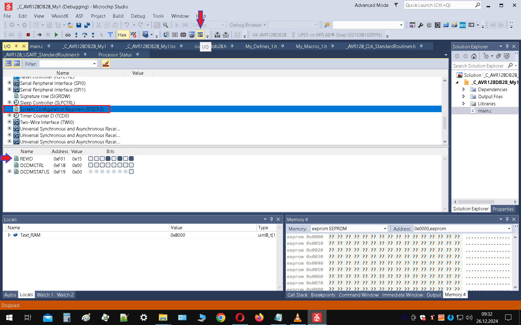
Microchip Studio Debugger Ansicht
Microchip Studio, AVR128DB828_My1, Debugger, Watch, Memory, eeprom, 0x8000, 0x0000
in „AVR128DA64 TCA1 funktioniert nicht mit alternativen Output?“ · Mikrocontroller und Digitale Elektronik · · Screenshots
-
 Bild
Bild
Microchip Studio Debugger Ansicht
Microchip Studio, AVR128DB82, Debugger, Watch, Memory, eeprom, 0x0000, 0x8000
in „welcher Debugger für 8bit Controller (AVR etc.) ?“ · Mikrocontroller und Digitale Elektronik · · Screenshots
-
PDF
Transistortester094k.pdf
Ergänzung zur Bedienung desAVR-Transistortester K.-H. Kübbeler Gilt nur für Testversion 0.94k Einleitung: Basierend auf der Software von Markus Frejek habe ich angefangen die Software zu modifizieren. Der Grund war zu Beginn eigentlich
-
PDF
ATMega164_324_644_1284pa.pdf
to enable SPI module. Figure 18-1. SPI Block Diagram (1) DIVIDER /2/4/8/16/32/64/128 I S I S Note: 1. Refer to Figure 1-1 on page 2, and Table 14-6 on page 82 for SPI pin placement. 164 8272C–AVR–06/11 ATmega164A/PA/324A/PA/644A/PA/1284/P The interconnection between Master and Slave
in „Hilfe bei AD-Wandler!“ · Mikrocontroller und Digitale Elektronik ·
-
Datei
AVRdude_Ergebnis_IDE_verbose.txt
sketch size: 1026 bytes (of a 14336 byte maximum) G:\Download\Arduino\arduino-0022\hardware/tools/avr/bin/avrdude -CG:\Download\Arduino\arduino-0022\hardware/tools/avr/etc/avrdude.conf -v -v -v -v -patmega168 -cstk500v1 -P\\.\COM7 -b19200 -D -Uflash:w:C:\Users\wps\AppData\Local\Temp\build350746234049397048
in „Flashen von Arduino“ · Mikrocontroller und Digitale Elektronik ·
-
Datei
SHT_TEST.c
first implementation of crc check 2006-08-27 0v2 - second release */ #define F_CPU 16000000 #include <avr/io.h> //Microcontroller specific library, e.g. port definitions #include <math.h> // #include <stdlib.h> // #include <inttypes.h> // #include <util/delay.h> #include "libsht.h" #include <avr/pgmspace.h
in „SHT11 an ATmega2560 Es funktioniert nicht“ · Mikrocontroller und Digitale Elektronik ·
-
PDF
Umsetzung_und_Implementierung_einer_FFT_f_r_8.pdf
Programmen berücksichtigt werden. 10 0⋅707 = 7,07 904,96 10 0⋅707 128 ⋅ )= = 7,07 128 Der Vorteil bei der Verwendung eines Skalierungsfaktors der Potenz 2 ist die Division. Bei binären Zahlen bedeutet eine Verschiebung aller Bits um eine Stelle nach rechts, eine Division
in „FFT Tutorial für AVR“ · Mikrocontroller und Digitale Elektronik ·
-
PDF
AVR310_Using_the_USI_module_as_a_I2C_master.pdf
. A STOP condition is defined by a low to high transition on the SDA line while the SCL is high. 2 AVR310 2561B-AVR-09/04 AVR310 If a Slave device cannot handle incoming data until it has performed some other function, it can hold SCL low to force the Master into a wait-state. All data packets transmitted
in „ATTiny2313 I2C - Master (Peter Fleury) / Slave (jtronics)“ · Mikrocontroller und Digitale Elektronik ·
-
Datei
ssd1306.c
-> 14.04.2018 09:13:07 * Description -> Treiber unterstützt das I2C Protokoll. * * * */ #include <avr/io.h> #include <avr/interrupt.h> #include <string.h> #include <stdlib.h> #include "I2C.h" #include "ssd1306.h" static uint8_t DisplayRam[ ( SSD1306_LCD_Width * SSD1306_LCD_HEIGHT ) / 8 ] = "0xFF"; static
in „SSD1306/1309 Library zum Darstellen von Text auf OLED Displays“ · Projekte & Code ·
-
PDF
lcdcon_320240.pdf
139 0 255 zeichnet ein 40x40 großes, schwarzes Rechteck, mit einem weißen Rand 19 160 0 120 15 64 128 zeichnet einen Kreis mit dem Mittelpunkt 160,120 und dem Radius 15, gefüllt mit der dunkelsten Graustufe und einem etwas helleren Rand 16 170 2 16 1 8 0 1 2 4 8 16 32 64 128 zeichnet ein 8x8 Pixel großes Bild mit den Daten 1, 2, 4, 8, 16, 32, 64, 128 (=schräge Linie) an die Position 16, 16 16 170 4 16 2 8 1 0 3 0 12 0 48 0 192zeichnet ein 8x8 Pixel großes Bild (schräge Linie) an die Position 16, 16, also 3 0 12 0 48 0 192 0 genauso wie vorher, nur
in „Grafikfähiger LCD Controller für 320x240 LCD mit 4 Graustufen“ · Projekte & Code ·
-
Datei
pegasus_5x7_font.bas
'############################################################### ' Bascom AVR Test for the Powertip PH9867C CSTN Color Display ' This demo displays a text screen with 15 x 7 characters using ' 5x7 Font. ' Display Controller Type: ST7626 ' Tested on ATMega8, 70% Flash used. Internal
in „Mini-Farbdisplay (+mehr) für 1 Euro“ · Mikrocontroller und Digitale Elektronik ·
-
Datei
clock.c
" #include <avr/io.h> #include <avr/interrupt.h> //Bitzähler für RX Bit volatile unsigned char rx_bit_counter = 0; //64 Bit für DCF77 benötigt werden 59 Bits volatile unsigned long long dcf_rx_buffer = 0; //Hilfs Sekunden
in „xmega und dcf von u. radig“ · Mikrocontroller und Digitale Elektronik ·
-
PDF
Eng_ET-TFT240320TP-3.2.pdf
tointerfaceBoard TFT240320T3.2 that is describedin thetopic 3.1)and3.2)supportsETT example. It uses MCU AVR MEGA128,PIC 18F8722 to interface with MCU5V andthen usesMCUARM7 LPC2138 to interface withMCU3.3V. Bothconnectingtypesofthese circuitscanbeadaptedand appliedtointerfacewithotherMCUnumbers orfamilies.However
in „LCD 240x320 color + touch screen module“ · Mikrocontroller und Digitale Elektronik ·
-
Datei
debug_error.asm
89 83 std Y+1, r24 ; 0x01 // ensure High level for some time SENSOR_PORT |= (1<<SENSOR_PIN ); 192: 28 9a sbi 0x05, 0 ; 5 SENSOR_DDR |= (1<<SENSOR_DD_BIT); 194: 20 9a sbi 0x04, 0 ; 4 #else //round up by default __ticks_dc = (uint32_t)(ceil(fabs(__tmp))); #endif __builtin_avr_delay_cycles(__ticks_dc);
in „Fehler bei einfacher Integer-Division?“ · Mikrocontroller und Digitale Elektronik ·
-
Datei
main.c
#include <util/delay.h> #include <avr/io.h> #include <avr/interrupt.h> #include <stdint.h> int main() { DDRA=0xff; //Alle von Port A als Ausgang while(1) {PORTD=0x00; PORTA=0xff; //würde Ich so machen weil sonst siehst du nix if (PIND &
in „Timer1 Compare Mode Probleme,Mega16“ · Mikrocontroller und Digitale Elektronik ·
-
PDF
vorstellung.pdf
A11 8 13 XTAL1 (ADC2)PA2 38 21 A12 CE 5 G2 (ADC1)PA1 39 29 A13 WE 12 32 AREF (ADC0)PA0 40 30 A14 OE 28 30 AVCC 31 A15 31 AGND (SCK)PB7 8 32 A16 GND 9 (MISO)PB6 7 GND 25 10 VCC (MOSI)PB5 6 11 GND (SS)PB4 5 SRAM, 128K*8 (AIN1/OC0)PB3 4 (AIN0/INT2)PB2 3 (T1)PB1 2 (T0/XCK)PB0 1 (TOSC2)PC7 29 (TOSC1)PC6 28
in „Analogditigitalwandler für Kamerachip“ · Mikrocontroller und Digitale Elektronik ·
-
PDF
ttester.pdf
8-bit AVR with 4/8/16/32KBytes In-System Programmable Flash - ATme- ga48 - ATmega328,. Manual, 8271D-AVR-05/11, 2011 [4] Atmel Corporation Atmel AVR126: ADC of megaAVR in Single Ended Mode,. Application Note,
in „Sammelbestellung Transistortester III - schnelle Runde“ · Markt ·
-
PDF
RN-Mega_Board.pdf
für Anwender, Bastler und Entwickler konzipiert die bereits Erfahrungen mit AVR-Controllern haben oder denen die kleineren AVR´s wie Mega8/Mega32 oder Mega128 noch nicht ganz ausreichen bzw. zu wenig Reserven bieten. Dieses Modul nutzt den neusten Controllerchip ATMega2560. Er dürfte derzeit ohne Frage einer der leistungsfähigsten AVR Controller überhaupt sein. Er bietet zum Beispiel wesentlich mehr Funktionen, Speicher als der recht bekannte Mega128. Dennoch ist dieses Modul genauso einfach zu programmieren wie auch die kleineren
in „ATmega2560 spinnt“ · Mikrocontroller und Digitale Elektronik ·
-
Datei
test.ino.asm
0xe4 <.do_clear_bss_loop> 000000ec <__do_global_ctors>: ec: 10 e0 ldi r17, 0x00 ; 0 ee: cd e5 ldi r28, 0x5D ; 93 f0: d0 e0 ldi r29, 0x00 ; 0 f2: 04 c0 rjmp .+8 ; 0xfc <__do_global_ctors+0x10> f4: 21 97 sbiw r28, 0x01 ; 1 f6: fe 01 movw r30, r28 f8: 0e 94 d9 02 call 0x5b2 ; 0x5b2 <__tablejump2__> fc:
in „Atmega328 1-Wire mit Timer CTC/PWM“ · Mikrocontroller und Digitale Elektronik ·
-
Datei
mit_kontrollausgabe.asm
0x94 <.do_clear_bss_loop> 0000009c <__do_global_ctors>: 9c: 10 e0 ldi r17, 0x00 ; 0 9e: c5 e3 ldi r28, 0x35 ; 53 a0: d0 e0 ldi r29, 0x00 ; 0 a2: 04 c0 rjmp .+8 ; 0xac <__do_global_ctors+0x10> a4: 21 97 sbiw r28, 0x01 ; 1 a6: fe 01 movw r30, r28 a8: 0e 94 7d 03 call 0x6fa ; 0x6fa <__tablejump2__> ac:
in „AVR Inline Optimierung kaputt?“ · Mikrocontroller und Digitale Elektronik ·
-
Datei
bootloader.lst.txt
0x3f, r1 ; 63 34: cf e5 ldi r28, 0x5F ; 95 36: d4 e0 ldi r29, 0x04 ; 4 38: de bf out 0x3e, r29 ; 62 3a: cd bf out 0x3d, r28 ; 61 3c: 78 d0 rcall .+240 ; 0x12e <main> 3e: 8c c0 rjmp .+280 ; 0x158 <_exit> 00000040 <__bad_interrupt>:
in „2 Programme in einem AVR“ · Mikrocontroller und Digitale Elektronik ·