-
Datei
MJoy.asm
.equ JoystickLastDataPIDBit =3 .equ JoystickReportID =0b00010000 .equ JoystickReportIDBit =4 ;.equ CRC5poly =0b00101 ;CRC5 polynomial ;.equ CRC5zvysok =0b01100 ;CRC5 remainder after successful CRC5 .equ CRC16poly =0b1000000000000101 ;CRC16 polynomial ;.equ CRC16zvysok =0b1000000000001101 ;CRC16 remainder
in „AVR Joystickprogrammierung“ · Mikrocontroller und Digitale Elektronik ·
-
Datei
MJoy.asm
.equ JoystickLastDataPIDBit =3 .equ JoystickReportID =0b00010000 .equ JoystickReportIDBit =4 ;.equ CRC5poly =0b00101 ;CRC5 polynomial ;.equ CRC5zvysok =0b01100 ;CRC5 remainder after successful CRC5 .equ CRC16poly =0b1000000000000101 ;CRC16 polynomial ;.equ CRC16zvysok =0b1000000000001101 ;CRC16 remainder
in „error: Operand 1 out of range:“ · Mikrocontroller und Digitale Elektronik ·
-
PDF
ds1990a.pdf
unique serial number. The last 8 bits are is a slave device. The bus master is typically a micro- a CRC of the first 56 bits. See Figure 2 for details. The controller or PC. For small configurations, the 1-Wire 1-Wire CRC is generated using a polynomial generator communication signals can be generated
in „V 30 iButton DS1990A“ · Markt ·
-
PDF
AS5410_DataSheet_Rev1.5.pdf
in progress D0 (LSB) ED 1= E²PROM write cycle completed 8.8 Register 0108h: Cycle Redundancy Check (CRC): Register Access Bit Function Note D15 (MSB) CRC15 D14 CRC14 D13 CRC13 D12 CRC12 D11 CRC11 D10 CRC10 D9 CRC9 0108h: D8 CRC8 CRC R D7 CRC7 Checksum Reading Check D6 CRC6 D5 CRC5 D4 CRC4 D3 CRC3 D2 CRC2 D1 CRC1 D0 (LSB) CRC0 www.austriamicrosystems.com/AS5410 Revision 1.5 16 - 28 AS5410 Data Sheet 8.9 Register 0110h: On-chip temperature sensor: Register Access Bit Function Note D15 (MSB) T15 D14 14 D13 T13
in „SPI funktioniert nicht“ · Mikrocontroller und Digitale Elektronik ·
-
Datei
mmc.c
define ACMD13 (0xC0+13) /* SD_STATUS (SDC) */ #define CMD16 (0x40+16) /* SET_BLOCKLEN */ #define CMD17 (0x40+17) /* READ_SINGLE_BLOCK */ #define CMD18 (0x40+18) /* READ_MULTIPLE_BLOCK */ #define CMD23 (0x40+23) /* SET_BLOCK_COUNT (MMC) */ #define ACMD23 (0xC0+23) /* SET_WR_BLK_ERASE_COUNT (SDC) */ #define
in „ISR(SPI_STC_vect) wird nicht verlassen“ · Mikrocontroller und Digitale Elektronik ·
-
Datei
diskio.c
*/ #define ACMD13 (0x80+13) /* SD_STATUS (SDC) */ #define CMD16 (16) /* SET_BLOCKLEN */ #define CMD17 (17) /* READ_SINGLE_BLOCK */ #define CMD18 (18) /* READ_MULTIPLE_BLOCK */ #define CMD23 (23) /* SET_BLOCK_COUNT (MMC) */ #define ACMD23 (0x80+23) /* SET_WR_BLK_ERASE_COUNT (SDC) */ #define CMD24 (24)
in „STM32 <-> AVR“ · Mikrocontroller und Digitale Elektronik ·
-
Datei
sdmm.c
*/ #define ACMD13 (0x80+13) /* SD_STATUS (SDC) */ #define CMD16 (16) /* SET_BLOCKLEN */ #define CMD17 (17) /* READ_SINGLE_BLOCK */ #define CMD18 (18) /* READ_MULTIPLE_BLOCK */ #define CMD23 (23) /* SET_BLOCK_COUNT */ #define ACMD23 (0x80+23) /* SET_WR_BLK_ERASE_COUNT (SDC) */ #define CMD24 (24) /* WRITE_BLOCK
in „SD Karte shutdown“ · Mikrocontroller und Digitale Elektronik ·
-
Datei
mmc.c
over spi while(length) { spi_io(*data); data++; length--; }; }; // send cmd + arguments + default crc for init command. once in spi mode // we dont need crc so we can keep this constant void MMC_send_cmd(u08 cmd, u16 datah, u16 datal) { // default command sequence u08 buffer[6] ; // fill sequence with
in „SD Karte initialisieren“ · Mikrocontroller und Digitale Elektronik ·
-
Datei
GMII_ETH_TX_STREAM.v
d56: eth_dat <= 8'hBE; 11'd57: eth_dat <= 8'hEF; /*11'd12: eth_dat <= 8'h00;//05; // LÄNGE = DATEN + CRC 11'd13: eth_dat <= 8'h3E;//4A; 11'd14: eth_dat <= 8'h41; // Opcode 11'd15: eth_dat <= 8'h40; // Packet ID 11'd16: eth_dat <= 8'h02; // Device ID 11'd17: eth_dat <= 8'hAD; 11'd18: eth_dat <= 8'h00; /
in „Ethernetcontroller - Marvell PHY 88e1111“ · FPGA, VHDL & Co. ·
-
Datei
mmc.inc
Init OK pop tempu1 sbr StatusB,SDCARDok ldiw_m Z,txt_Ok ;"Ok" rcall Display_putStrFL ldi XL,3 ldi XH,17 rcall Display_pos ldiw_m Z,txt_mmc2 ;"Analysiere Karte ..." rcall Display_putStrFL ldi XL,103 ldi XH,17 rcall Display_pos rcall Cluster_Data_Store ;Funktion aus Fat ldsw X,fat_VBRA tstw X brne init_mmc_m01
in „SDKarte SPI gibt seltsame Antwort“ · Mikrocontroller und Digitale Elektronik ·
-
PDF
Datasheet_IVT-S_V1.02.pdf
command DB1 DB Value Remark 0 0x81 Response system errors 1 Specific Error Counter 0x01 Error Code CRC 0x02 Error Parameter CRC 0x03 Error CAN bus receive Data 0x04 Error CAN bus transmit Data 0x05 Error overtemp 0x06 Error undertemp 0x07 Error power failure 0x08 Error system clock 0x09 Error system
in „Strommessung bis 60V“ · Analoge Elektronik und Schaltungstechnik ·
-
PDF
AVR309_doc2556.pdf
USB lines to buffer in reverse order (LSB/MSB). 11 2556-PRELIMINARY-AVR-01/04 CheckCRCIn: Performs CRC (cyclic redundancy check) on received data packet. CRC is added to USB packet to detect data corruption. AddCRCOut: Adds CRC field into output data packet. CRC is calculated according to the USB specification from given USB fields. CheckCRC: Auxiliary routine used in CRC checking and addition. LoadDescriptorFromROM: Loads data from ROM to USB output buffer (as USB answer). LoadDescriptorFromROM- Loads data from ROM to USB output buffer
in „Programmer incl. neuem Code für Atmel AN910“ · Projekte & Code ·
-
Datei
sdio.patch
date: %d/%d\n", cid->mdt_1 & 15, 2000+((cid->mdt_0 & 15) << 4)+((cid->mdt_1 & 0xf0) >> 4)); + printf("CRC: 0x%02x, b0 = %d\n", cid->crc >> 1, cid->crc & 1); +} + +static void mvsdio_set_clock(unsigned int clock) +{ + unsigned int m; + + m = MVSDMMC_BASE_FAST_CLOCK/(2*clock) - 1; + + debug("mvsdio_set_clock
in „20Euro Embedded System mit ARM, 128MB ram und 256MB Flash“ · Mikrocontroller und Digitale Elektronik ·
-
Datei
sdio.patch
date: %d/%d\n", cid->mdt_1 & 15, 2000+((cid->mdt_0 & 15) << 4)+((cid->mdt_1 & 0xf0) >> 4)); + printf("CRC: 0x%02x, b0 = %d\n", cid->crc >> 1, cid->crc & 1); +} + +static void mvsdio_set_clock(unsigned int clock) +{ + unsigned int m; + + m = MVSDMMC_BASE_FAST_CLOCK/(2*clock) - 1; + + debug("mvsdio_set_clock
in „20Euro Embedded System mit ARM, 128MB ram und 256MB Flash“ · Mikrocontroller und Digitale Elektronik ·
-
Datei
rfid.ino
MI_ERR; } } //SetBitMask(CollReg, 0x80); //ValuesAfterColl=1 return status; } /* * Function:CalulateCRC * Description:Use MF522 to caculate CRC * Input parameter:pIndata--the CRC data need to be read,len--data length,pOutData-- the caculated result of CRC * return:Null */ void CalulateCRC(uchar *pIndata
in „Arduino leonardo invalid suffix "B9FD4" umgehen“ · Mikrocontroller und Digitale Elektronik ·
-
PDF
trm-868-eur-463941_4_.pdf
postfixes the data typical, yielding a link budget of 117dB. This mode reduces transmit with a 16-bit CRC. The 16-bit CRC error checking can be disabled to allow current consumption, allowing use with batteries that cannot supply the the host application to do its own error checking. Data is encoded using
-
PDF
trm-868-eur-463941.pdf
postfixes the data typical, yielding a link budget of 117dB. This mode reduces transmit with a 16-bit CRC. The 16-bit CRC error checking can be disabled to allow current consumption, allowing use with batteries that cannot supply the the host application to do its own error checking. Data is encoded using
-
Datei
ds1820.asm
schon mal nicht merken! iw_sr_8: st z+,datreg ; merke byte im zielspeicher mov temp1,temp3 ; hole crc aus merker rcall iwire_crc ; führe crc durch mov temp3,temp1 ; merke crc ld datreg,y+ ; hole das nächste byte aus der vorigen iwire-adresse iw_sr_9: inc temp2 ; bitcounter+1 cpi temp2,65 ; letztes bit
in „mehere ds1820 an einem bus“ · Mikrocontroller und Digitale Elektronik ·
-
PDF
SDHC_SDM04G7B7_08G7B7.pdf
ŋCRC Calculated CRC for default data is set here. Host System is responsible to re-calculate this CRC if any CSDcontentsarechanged. 2006-12-29 27/64 SD-M04G7B7 (VDC), SD-M04G7B7 (VDCCN), SD-M04G7B7K (VDC
in „SD-Karte - SDHC Karte“ · Mikrocontroller und Digitale Elektronik ·
-
PDF
BMP581.pdf
- T Recommendation X.25 (10/96). Following C-code sample shows the computation of the CRC-16 CCITT checksum: int datalength = 0; int datawidth = 0; int SIZE = 62; uint16_t Poly = 0x1021; uint16_t Initval = 0xFFFF; uint16_t crc ; uint16_t crc_temp; crc = Initval; for( datalength =0; datalength< SIZE; datalength++){ crc_temp = (OTP_DATA[datalength] << 8) ^ crc; for (datawidth = 0; datawidth < 8; datawidth++) { if ((crc_temp & 0x8000) != 0) { crc_temp = (crc_temp << 1) ^ Poly; } else { crc_temp = crc_temp << 1; } }
in „Datenlogger Pendeluhr“ · Mikrocontroller und Digitale Elektronik ·
-
PDF
DS2761.pdf
address, the host system can compute a CRC value from the first 56 bits of the address and compare it to the CRC from the DS2761. The host system is responsible for verifying the CRC value and taking action as a result. The DS2761 does not compare CRC values and does not prevent 14 of 24 DS2761 a command sequence from proceeding as a result of a CRC mismatch. Proper use of the CRC can result in a communication channel with a very high level of integrity
in „Akkustand mit AVR feststellen“ · Mikrocontroller und Digitale Elektronik ·
-
PDF
Modbus_RTU___Kommunikationshandbuch_fuer_EATON_DC1.pdf
Die Anzahl der zu bearbeitenden Parameter) durchführen zu können. 2.6.1.4 Zyklische Fehlerprüfung (CRC) Die Telegramme in der Betriebsart Modbus RTU beinhalten eine zyklische Fehlerprüfung (CRC = Cyclical Redundancy Check). Das CRC-Feld besteht aus zwei Bytes, die einen binären 16-Bit-Wert enthalten. Die CRC-Fehler- prüfung wird immer und unabhängig vom Paritätsprüfverfahren für die ein- zelnen Zeichen des Telegramms durchgeführt. Das CRC-Ergebnis wird vom Master an das Telegramm angehängt. Der Slave führt
in „ich bitte um Mitt-Hilfe in Sachen RS485; Modbus; Frquenzumrichter; qModMaster“ · Mikrocontroller und Digitale Elektronik ·
-
PDF
ADNS-2700.pdf
Read the OTP data byte from OTP_DATA register, 0x53 to complete the OTP read operation. 7. Read the CRC result stored in register 0xE9, 0xEA, 0xEB, 0xEC, if four register values not 0x00 means CRC has 7. Repeat Step 2 for more OTP read operations beengeneratedcorrectlyandverifiedaslockoperation success
in „USB Maus mit USART auslesen“ · Mikrocontroller und Digitale Elektronik ·
-
PDF
AVR32-64SD20-28-32-48-ProductBrief-DS40002417.pdf
memory scan • Verify the integrity of the entire Flash section, application code, and/or boot section • CRC-16-CCITT or CRC-32 (IEEE 802.3) – External interrupt on all general-purpose pins • Peripherals – 6-channel Event System for predictable and CPU-independent inter-peripheral signaling – One 16-bit Timer
-
Datei
smart.txt
revision not indicated) SATA Version is: SATA 3.2, 6.0 Gb/s (current: 6.0 Gb/s) Local Time is: Wed Aug 4 17:36:33 2021 CEST SMART support is: Available - device has SMART capability. SMART support is: Enabled AAM feature is: Unavailable APM feature is: Unavailable Rd look-ahead is: Enabled Write cache is:
in „Mint 19.2 zerschießt sein Dateisystem“ · PC Hard- und Software ·
-
PDF
uniTFT050-A.pdf
DC4 1 0 'R' crc16 derholen Send ACK Send DC3 len data ... ... crc16 5 Protokolleinstellungen Empfang DC4 5 0 'D' packet s4ze timeout crc16 sendbuffer 10 ms Send ACK Empfang DC4 1 0 'I' crc16 Pufferinformationenanfor
in „Probleme mit übertragung“ · Mikrocontroller und Digitale Elektronik ·
-
PDF
Datenblatt_uniTFT_050-A.pdf
DC4 1 0 'R' crc16 derholen Send ACK Send DC3 len data ... ... crc16 5 Protokolleinstellungen Empfang DC4 5 0 'D' packet s4ze timeout crc16 sendbuffer 10 ms Send ACK Empfang DC4 1 0 'I' crc16 Pufferinformationenanfor
in „Display am Attiny 841“ · Mikrocontroller und Digitale Elektronik ·
-
Datei
mmc_avr.c
*/ #define ACMD13 (0x80+13) /* SD_STATUS (SDC) */ #define CMD16 (16) /* SET_BLOCKLEN */ #define CMD17 (17) /* READ_SINGLE_BLOCK */ #define CMD18 (18) /* READ_MULTIPLE_BLOCK */ #define CMD23 (23) /* SET_BLOCK_COUNT (MMC) */ #define ACMD23 (0x80+23) /* SET_WR_BLK_ERASE_COUNT (SDC) */ #define CMD24 (24)
in „SD-SPI keine Antwort auf CMD0“ · Mikrocontroller und Digitale Elektronik ·
-
Datei
kk_bb.c
*/ #define ACMD13 (0x80+13) /* SD_STATUS (SDC) */ #define CMD16 (16) /* SET_BLOCKLEN */ #define CMD17 (17) /* READ_SINGLE_BLOCK */ #define CMD18 (18) /* READ_MULTIPLE_BLOCK */ #define CMD23 (23) /* SET_BLOCK_COUNT */ #define ACMD23 (0x80+23) /* SET_WR_BLK_ERASE_COUNT (SDC) */ #define CMD24 (24) /* WRITE_BLOCK
in „Problem FatFS + SPI“ · Mikrocontroller und Digitale Elektronik ·
-
Datei
msp430x1232.txt
section_user_main_off (rx) : ORIGIN = 0xE820, LENGTH = 0x0010 text (rx) : ORIGIN = 0xE830, LENGTH = 0x17AE section_user_crc16 (rx) : ORIGIN = 0xFFDE, LENGTH = 0x2 data (rwx) : ORIGIN = 0x0200, LENGTH = 256 vectors (rw) : ORIGIN = 0xffe0, LENGTH = 32 bootloader(rx) : ORIGIN = 0x0c00, LENGTH = 1K infomem(
in „MSP430 LinkerFile, Variablen- und DebugInformations-problem“ · Mikrocontroller und Digitale Elektronik ·
-
 Bild
Bild
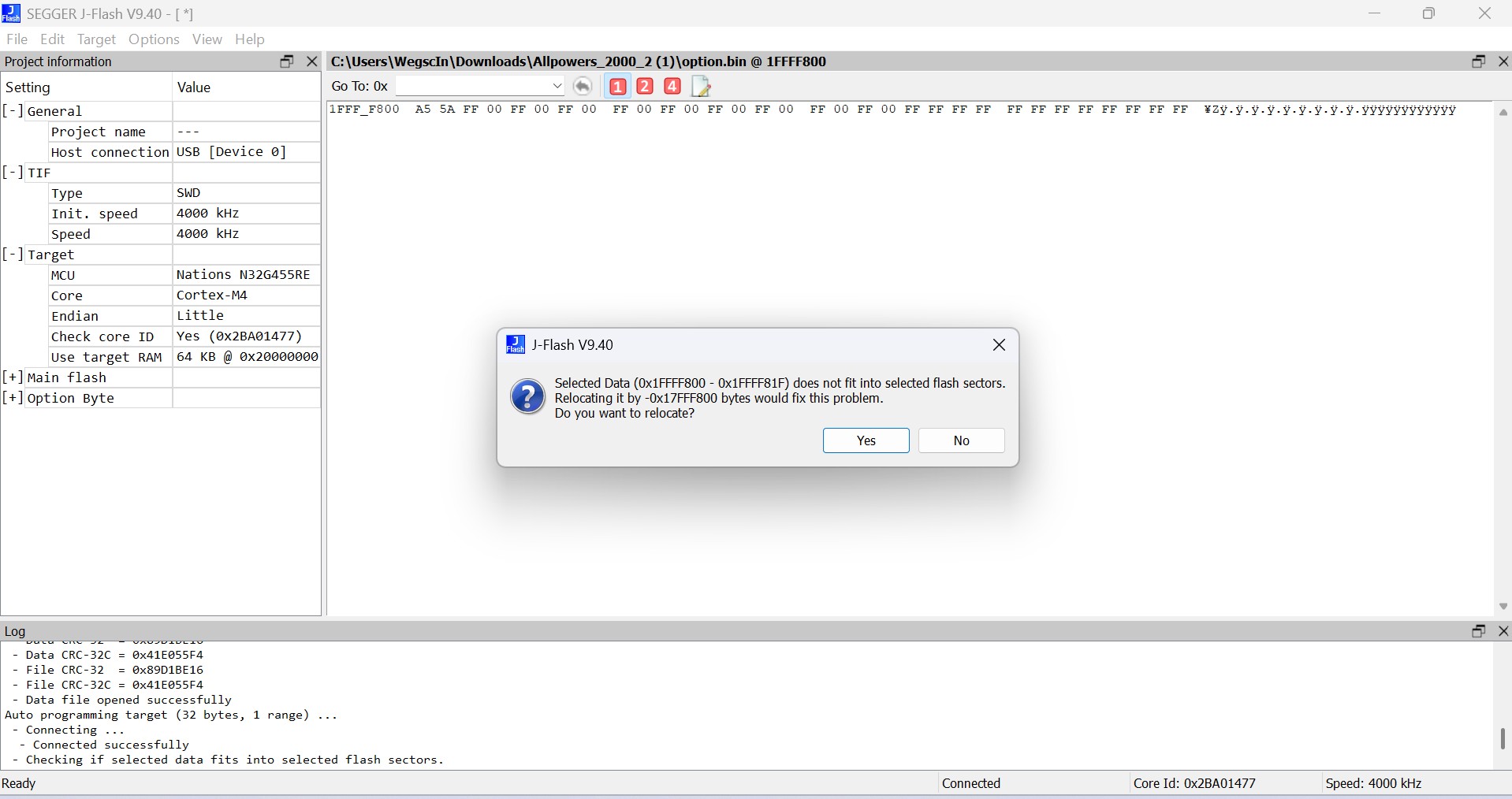
Fehlermeldung J-Flash beim Flashen eines Mikrocontrollers
Selected Data (0x1FFF800 - 0x1FFF81F) does not fit into selected flash sectors. Relocating it by -0x17FF800 bytes would fix this problem. Do you want to relocate? Yes No Log Data CRC-32 = 0x41E055F4 File CRC-32 = 0x40D3BE16 File CRC-32C = 0x41E05554 Data file opened successfully Auto programming target
in „ALLPOWERS S2000 PRO Reparaturhilfe“ · Mikrocontroller und Digitale Elektronik · · Screenshots
-
PDF
MELEXIS_Sensor-IC-MLX90316KDC_EN.pdf
....................................31 17.2. A NALOG O UTPUT W IRING WITH THEMLX90316 INTSSOPP ACKAGE ....................................................31 17.3. PWML OW SIDE OUTPUT W IRING...................................................
in „MLX90316 mit Atmega8 über SPI“ · Mikrocontroller und Digitale Elektronik ·
-
Datei
RFM_22.h
Device_Status; //Register 0x03 typedef union tagInterrupt1_Status { byte _byte; struct{ unsigned char CRC_Error:1; // When set to 1 the cyclic redundancy check has failed unsigned char valid_packet_recieved:1; // When set to 1 a valid packet has been received unsigned char Packet_sent_Int:1; // When set
-
Datei
Therm.txt
Temperature from SCRATCHPAD MOV @R0,A INC R0 DJNZ R6,TCOTEM2 CALL TERES ;RESET CALL TEPRE CALL ds1820crc_ok JNC DCFG1 ;jump if CRC Check failure CALL CALCULATE MOV A,TEP1 CJNE A,#85H,REP1 JMP READ_TEMP1 REP1: MOV TEMP1,TEP1 MOV TEMP1D,TEP2 CLR MIN1 ;ASSUME +VE MOV A,RAM+1 JNB ACC.0,DCFG1 SETB MIN1 ;minus
in „Programm(A51) DS1820 auf DS18b20 Umstellen“ · Mikrocontroller und Digitale Elektronik ·
-
Datei
Therm.txt
Temperature from SCRATCHPAD MOV @R0,A INC R0 DJNZ R6,TCOTEM2 CALL TERES ;RESET CALL TEPRE CALL ds1820crc_ok JNC DCFG1 ;jump if CRC Check failure CALL CALCULATE MOV A,TEP1 CJNE A,#85H,REP1 JMP READ_TEMP1 REP1: MOV TEMP1,TEP1 MOV TEMP1D,TEP2 CLR MIN1 ;ASSUME +VE MOV A,RAM+1 JNB ACC.0,DCFG1 SETB MIN1 ;minus
in „Programm(A51) DS1820 auf DS18b20 Umstellen“ · Mikrocontroller und Digitale Elektronik ·
-
PDF
2006111335_Texas-Instruments-BQ7692003PWR_C601650.pdf
is calculated over the slave address, register address, and data. The CRC for subsequent data bytes is calculated over the data byte only. The CRC polynomial is x8 + x2 + x + 1, and the initial value is 0. 2 2 When the slave detects a bad CRC, the I C slave will NACK the
in „bq76940 balancing“ · Mikrocontroller und Digitale Elektronik ·
-
PDF
datasheet_bq2023.pdf
2001 APPLICATION INFORMATION read memory/field CRC The read memory/field CRC command reads part or all of the 271 memory addresses shown in the register map with an 8-bit CRC generated at the end of the 271-byte register map. The flowchart in figure
in „Mit MSP430 einen IC( bq2023) programmieren“ · Mikrocontroller und Digitale Elektronik ·
-
PDF
STM32MP151A_Block_Diagram.pdf
TimeStamp T n GENerator TSGEN T EXTI 16ext 176 GIC T C a 128 bits T DAP S ) T (JTAG / SWD) I DCMI 14b 17 Cortex-A7 CPU $ z F (Camera I/F) 650 MHz + MMU + FPU + L H T SYSRAM 256KB DLYBSD3 NEON T B M (SDMMC3 DLY control) 6 6 T ROM 128KB F L 32K D$ 2 2 F T SDMMC3 D 4b 10 32K I$ ( T BKPSRAM 4KB @ O Y c F (HS
in „STM32MP1 von ST“ · Mikrocontroller und Digitale Elektronik ·
-
Datei
kueche_2.lst
TIMER0_COMPA 00000e 9518 reti ;15= TIMER0_COMPB 00000f 9518 reti ;16= USI_START 000010 9518 reti ;17= USI_OVERFLOW 000011 9518 reti ;18= EE_READY 000012 9518 reti ;19= WDT_OVERFLOW .endif ; Any interrupt may use iwr0..isreg unless it enables interrupts .def iwr0 = r16 .def iwr1 = r17 .def iwr2 = r2
-
PDF
GD32VF103_User_Manual_EN_V1.0.pdf
register (CRC_DATA) Address offset: 0x00 Reset value: 0xFFFF FFFF This register has to be accessed by word (32-bit). 31 30 29 28 27 26 25 24 23 22 21 20 19 18 17 16 DATA [31:16] rw 15 14 13 12 11 10 9 8 7 6 5 4 3
in „STM32F103C8T6 => GD32VF103C8T6“ · Mikrocontroller und Digitale Elektronik ·
-
Datei
mapfile.txt
bootloader_check.o() .text 0x0000e006 0x8 bootloader_check.o 0x0000e006 bootloader_check_char .section_crc_check 0x0000e020 0x8 crc_check.o() .text 0x0000e020 0x8 crc_check.o 0x0000e020 check_program_crc .section_bootloader 0x0000e030 0x591 bootloader.o() .text 0x0000e030 0x550 bootloader.o 0x0000e402 bootloader_protokoll
in „MSP430 LinkerFile, Variablen- und DebugInformations-problem“ · Mikrocontroller und Digitale Elektronik ·
-
Datei
SD_SPI.asm
adr_SD_PHYS_SEKTOR_OLD_BYTE3),temp7 STS(adr_SD_PHYS_SEKTOR_OLD_BYTE4),temp8 ; vergleich cp temp1,temp5 brne SD_CMD17_START cp temp2,temp6 brne SD_CMD17_START cp temp3,temp7 brne SD_CMD17_START cp temp4,temp8 brne SD_CMD17_START ret ; hiermit kann der CHACHE deaktiviert werden SD_CMD17_START: ; CD auf HIGH & 3xDummy
in „SD-Karte Initialisierung Read Write FAT ATmega8 (Assembler)“ · Projekte & Code ·
-
PDF
bq76940.pdf
is calculated over the slave address, register address, and data. The CRC for subsequent data bytes is calculated over the data byte only. The CRC polynomial is x8 + x2 + x + 1, and the initial value is 0. 2 2 When the slave detects a bad CRC, the I C slave will NACK the
in „Schaltung für aktiven 3s Balancer gesucht“ · Analoge Elektronik und Schaltungstechnik ·
-
Datei
telegramm.c
131: /* Zusatzbyte 10 */ case 134: case 135: case 136: case 137: case 138: case 139: case 140: /* CRC-Byte 1 */ case 143: case 144: case 145: case 146: case 147: case 148: case 149: /* CRC-Byte 2 */ bitpuffer>>=1; if (PIND & (1<<PD4)) { bitpuffer |= (BITMASKE_DATA); } break; /* letzten Bits der Info-, Zusatz- oder CRC-Bytes */ case 24: case 33: case 42: case 51: case 60: case 69: case 78: case 87: case 96: case 105: case 114: case 123: case 132: case 141: case 150: bitpuffer>>=1; if (PIND & (1<<PD4)) { bitpuffer
in „sporadische Fehler mit Interrupt“ · Mikrocontroller und Digitale Elektronik ·
-
Datei
rfm69.c
length, No DC-free encoding/decoding, CRC-Check, No Address filter rfm_cmd(0x3810, 1); // Max. Payload-Length 16 zeichen rfm_cmd(0x3C80, 1); // Tx-Start-Condition: FIFO not empty rfm_cmd(0x3DA0, 1); // Packet-Config2 // Preamble length 3 bytes
in „Wer verwendet RFM69?“ · Mikrocontroller und Digitale Elektronik ·
-
PDF
elabel20-a.pdf
for RS-485 15 ADR2 In Address 2 for RS-485 BAUDRATEN 16 BUZZ Out H: Buzzer output (L: Buzzer off) 17 DPROT In L: Disable Smallprotokoll Die Baudrate wird über die Pins 6, 7 und 8 (Baud0..2) do not connect for normal operation eingestellt.DasDatenformatistfesteingestelltauf8Datenbits, 18 PWR Out L: Normal
in „ePaper von EA - Auswahl Font“ · Mikrocontroller und Digitale Elektronik ·
-
Datei
communication.c
{ //Assume (TW_TxBufIndex == 0) and (TW_TxBufCtr == # of bytes of data, not incl PEC). temp = FastCRC(0, (TWAR & 0xFE)); //use the SLA+W address temp = FastCRC(temp, CurrentCmd); temp = FastCRC(temp, (TWAR | 1)); //use the SLA+R address do {temp = FastCRC(temp, TW_TxBuf[TW_TxBufIndex++]);} while(TW_TxBufIndex
in „Error: undeclared (first use in this function)“ · Mikrocontroller und Digitale Elektronik ·
-
Datei
mmc_stm32f1.c
*/ #define ACMD13 (0x80+13) /* SD_STATUS (SDC) */ #define CMD16 (16) /* SET_BLOCKLEN */ #define CMD17 (17) /* READ_SINGLE_BLOCK */ #define CMD18 (18) /* READ_MULTIPLE_BLOCK */ #define CMD23 (23) /* SET_BLOCK_COUNT (MMC) */ #define ACMD23 (0x80+23) /* SET_WR_BLK_ERASE_COUNT (SDC) */ #define CMD24 (24)
in „STM32F103: Problem mit ChanFat und SD karte“ · Mikrocontroller und Digitale Elektronik ·
-
PDF
TM56M152A-tenxtechnology.pdf
Refer to the “Electrical Characteristics Graphs”. 16. Operating Temperature Range : -40°C to + 105°C 17. Table Read Instruction: 16-bit ROM data lookup table 18. Integrated 16-bit Cyclic Redundancy Check (CRC) function 19. Instruction set: 39 Instructions 20. I/O ports: Maximum 14 programmable I/O pins
in „MCU identifikation/Datenblatt - MC9989A0ZQ“ · Mikrocontroller und Digitale Elektronik ·
-
PDF
S32K-RM.pdf
ENET_RMON_R_MC_PKT).......................................................2051 57.5.66 Rx Packets with CRC/Align Error Statistic Register (ENET_RMON_R_CRC_ALIGN)............................2052 57.5.67 Rx Packets with Less Than 64 Bytes and Good CRC Statistic Register (ENET_RMON_R_UNDERSIZE).............