SINKING. Consult factory for Military grade parts. ELECTRICAL CHARACTERISTICS VCC = 16V, V BAT = 8V, V MAX (maximumoperating V ) = CCV, no load on any outputs, unless otherwise noted. (Notes 7, 8) PARAMETER CONDITIONS MIN TYP MAX UNITS Overall Supply Current VPROG = 2.7V, VCC ≤20V 2.90 4.3 mA V = 2.7V, 20V
Typical Weight: 6.8 grams (0.22 oz.) mm (inches) Typical Volume: 2.4 cubic centimeters (0.14 cubic inch) Max Rev Charge: 1 microampere Energy Density: 183 milliwatt hr/g, 647 milliwatt hr/cc Typical Li Content: < 0.3g Operating Temp: -30C to 60C Self Discharge: ~1% / year 24.50 (0.965) 3.45 (0.136) Ref. 24.30 (0.957) 3.15 (0.124) Ref. Safety: R1.25 (0.049) Ref. 22.0 (.866) 1.00 (0.039) Ref. Max Minimum (1) KEEP OUT OF REACH OF CHILDREN. Swallowing may lead to R0.75 (0.030) Ref. serious injury or death in as little as 2 hours due to chemical burns and 5.00 (0.197) potential perforation of the
Typical Weight: 6.8 grams (0.22 oz.) mm (inches) Typical Volume: 2.4 cubic centimeters (0.14 cubic inch) Max Rev Charge: 1 microampere Energy Density: 183 milliwatt hr/g, 647 milliwatt hr/cc Typical Li Content: < 0.3g Operating Temp: -30C to 60C Self Discharge: ~1% / year 24.50 (0.965) 3.45 (0.136) Ref. 24.30 (0.957) 3.15 (0.124) Ref. Safety: R1.25 (0.049) Ref. 22.0 (.866) 1.00 (0.039) Ref. Max Minimum (1) KEEP OUT OF REACH OF CHILDREN. Swallowing may lead to R0.75 (0.030) Ref. serious injury or death in as little as 2 hours due to chemical burns and 5.00 (0.197) potential perforation of the
Guten Abend, Habe vor einen MAX7456 an einem STM32 zu betreiben. Der TestCode mit dem Anzeigen eines "SAMPLE" Text funktionierte auch ohne Probleme. Nachdem ich allerdings begonnen habe zu "spielen" und versucht habe einen Code
exakte Lösung, möglicherweise mit mehr Rechenaufwand? Wenn die Zahlen immer so klein sind (z.B. max 256), dann würde ich fast brute force jeder der 256 Ziel-mittelwerte durchprobieren: [c] int solution = 0; int solution_rsme = MAX_INT; for(int sol=0; sol < 256; ++sol) { * falls keine Zahl
viel Rechenzeit benötigen. > > > Was für Wertebereiche haben die Zahlen in den Arrays? 0 bis max. 400, daher uint16
Loss <20 <17 <18 dB Performance for Input Signals in the 1.0 - 2.0 GHz Band (+15dBm Drive) Min. Typ. Max. Fo Isolation (with respect to input level) 42 50 dB 3Fo Isolation (with respect to input level) 40 50 dB 4Fo Isolation (with respect to input level) 30 35 dB 12 ElizabethDrive, Chelmsford, MA Phone
: ±0.5 nm Tolerance: ±0.5 nm Orange Color Bins [1] Dom. Wavelength (nm) Bin ID Min. Max. A 597.0 600.0 B 600.0 603.0 C 603.0 606.0 D 606.0 609.0 E 609.0 612.0 F 612.0 615.0 Tolerance: ±1 nm Light Intensity (Iv) Bin Limits1] Intensity (mcd) Intensity (mcd) Bin ID Min. Max. Bin ID Min. Max
15V, IOUT = 0, J = 25°C, unless otherwise noted. LT1019A LT1019 SYMBOL PARAMETER CONDITIONS MIN TYP MAX MIN TYP MAX UNITS Output Voltage Tolerance 0.002 0.05 0.02 0.2 % TC Output Voltage LT1019C (0°C to 70°C) 3 5 5 20 ppm/°C Temperature Coefficient LT1019M(–55°C to 125°C) 5 10 8 25 ppm/°C (Note 2) LT1019I
M24C32 Table 13. SO8 - 8 lead Plastic Small Outline, 150 mils body width mm inches Symb. Typ. Min. Max. Typ. Min. Max. A 1.35 1.75 0.053 0.069 A1 0.10 0.25 0.004 0.010 B 0.33 0.51 0.013 0.020 C 0.19 0.25 0.007 0.010 D 4.80 5.00 0.189 0.197 E 3.80 4.00 0.150 0.157 e 1.27 – – 0.050 – – H 5.80 6.20 0.228
) 4.8 5.0 0.189 0.197 E 5.8 6.2 0.228 0.244 e 1.27 0.050 e3 3.81 0.150 F (1) 3.8 4.0 0.15 0.157 L 0.4 1.27 0.016 0.050 M 0.6 0.024 SO8 S 8° (max.) (1) D and F do not include mold flash or protrusions. Mold flash or potrusions shall not exceed 0.15mm (.006inch). 5/7 TL7700A Series mm inch DIM. OUTLINE AND MIN. TYP. MAX. MIN. TYP. MAX. MECHANICAL DATA A 3.32 0.131 a1 0.51 0.020 B 1.15 1.65 0.045 0.065 b 0.356 0.55 0.014 0.022 b1 0.204 0.304 0.008 0.012 D 10.92 0.430 E 7.95 9.75 0.313 0.384 e 2.54 0.100 e3 7.62 0.300
Max S. schrieb im Beitrag #4790508: > Was bringen Standards wenn aber nicht jeder Compiler sie nutzt?!? Umgekehrt: Was nutzt ein Compiler, der keinem Standard folgt?
überwiegenden Mehrheit der für den PC benutzten Pascaldialekte diesen speziellen Schalter. Das von Max genannte AVRco-Pascal ist da eine Ausnahme. Zeno
Recovery Time l High Surge Current Capability C D Mechanical Data DO-201AD l Case: Molded Plastic Dim Min Max Min Max l Terminals: Solder Plated, Solderable A 25.4 — 1.000 — B 8.50 9.50 0.335 0.374 per MIL-STD-750, Method 2026 l Polarity: Cathode Band or Cathode Notch C 1.20 1.30 0.047 0.051 l Marking: Type
4.75V to 15.75V, internal or external reference (2.475V V V – 2.7V), unless otherwise noted. A MIN MAX CC REF CC SYMBOL PARAMETER CONDITIONS MIN TYP MAX UNITS Power Supply VCC Positive Supply Voltage For Specified Performance 4.75 15.75 V ICC Supply Current 4.75V V CC 5.25V 350 600 A 4.75V V CC 15.75V
___________________________________ Package Information (continued) A INCHES MILLIMETERS X DIM MIN MAX MIN MAX A 0.053 0.069 1.35 1.75 7 A1 0.004 0.010 0.10 0.25 7 B 0.014 0.019 0.35 0.49 0 C 0.007 0.010 0.19 0.25 5 D 0.189 0.197 4.80 5.00 E H E 0.150 0.157 3.80 4.00 e 0.050 BSC 1.27 BSC H 0.228 0.244
to +85 °C unless otherwise specified Parameters Conditions Min Typ Max Units Input Voltage Range 4.0 — 5.25 V Output Voltage Output Current = 1 to 100 mA* 3.0 3.3 3.6 V VBUS Detection Input Threshold 1.0 1.8 4.0 V Bias Current — 110 — µA *Note: The maximum regulator supply
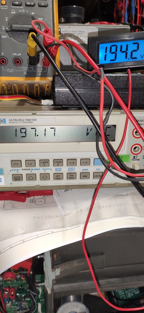
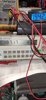
mV Ω mA OFF V mA µA 10A MAX FUSED CAT III 1000V 194.2 V 3478A MULTIMETER HEWLETT PACKARD 197.17 V RANGE/N. DIGIT 2 WIRE Ω 4 WIRE Ω AUTO ZERO TEST/RESET ADRS CAL SGL TRIG SRQ LOCAL AUTO MAN INT TRIG Bestückplan 04:02:97
der Timer unterschiedlich Timer1 zählt bis 1024 aber Timer 2 nur bis 256. zu 2 grensen sind ie max werte also 1024 und 256 z.B. die 1,3,8 ist er wert vom PWM vereinfacht wie lange die Spannung anliegt zB. 1/256,3/268,8/268 der Grundfrequenz Gruß Andreas
millimeters are control dimensions, dimensions in inches are approximate DIM Millimeters Inches MIN TYP MAX MIN TYP MAX A 15,00 15,50 16,00 0,591 0,610 0,630 A1 5,90 6,10 6,30 0,232 0,240 0,248 A2 2,10 2,30 2,50 0,083 0,091 0,098 (1) b 3,10 3,40 3,70 0,122 0,134 0,146 b (2) 3,50 3,80 4,10 0,138 0,150 0,161
= 46 Watt zuverlässig am Lautsprecher bringt. Auch hier hier weiss ja niemand, ob die 32V wirklich max sind oder bloss recommended. http://www.dse-faq.elektronik-kompendium.de/dse-faq.htm#F.30 Hier steht eine kommerzielle Auslegung für ein Netzteil drin http://www.ti.com/lit/an/snaa057b/snaa057b.pdf
drumrum bauen kann. https://www.hifi-selbstbau.de/index.php?option=com_content&view=article&id=197 Dann braucht man noch ein Messmikrophon und eine Auswertung (beispielsweise Neutrik A1) um überprüfen zu können, ob die Theorie überhaupt in der Praxis auch hinhaut (kleine Abweichungen beim Aufbau
products/290231/Kemo-Super-Breitband-Universal-Vorverstaerker-B073-Bausatz-12-30-V-DC-Ausgangsleistung-Max.-2-V.html /leider ohne Gehäuse/. Alternativ hier ein spezieller mono Mixer für 4 Mikrophone: http://www.voelkner.de/products/267543/Monacor-MMX-4-Mikrofon-Mischpult.html /Der kann aber dann nur
300€ aber nicht diesen Schrott. Schon gelesen: >Anmelde- und Gebührenpflichtige Funkfrequenz von 197Mhz Das heißt, du darfst das Ding zwar kaufen aber nicht betreiben! Ich frage mich manchmal wirklich wo das noch hinführen soll. Auf der einen Seite ist niemand mehr bereit für Qualität einen Pfennig
einrechnen muss sollte man auch Leistung messen wollen.Aber ich habe auch kleinere N-Abschwächer bis max. 2W...die Benutze ich auch hier und da....beim CMU sind sie aber nicht wirklich wichtig..der kann ja mindestens 2W ab..viele Geräte mögen aber max. 100mW 73
Bei mir geht der Audio-Generator ebenfalls aus sobald ich ins Spektrum wechsle. @souleye Ein Max-Hold ist im Spektrum aber möglich. Jedoch können nicht mehrere Traces angezeigt werden.
Sinking Current operation with a full set of specifications at 5V. ■ Guaranteed Offset Voltage: 50µV Max Specifications at ±15V are also provided. ■ Guaranteed Low Drift: 1.3µV/°C Max The LT1006 has a low offset voltage of 20µV, drift of ■ Guaranteed Offset Current: 0.5nA Max 0.2µV/°C, offset current of
MSC1400.PDF 03-20-00 SA5.0 thru SA170A ELECTRICALCHARACTERISTICSAT25 C ° PART BREAKDOWN TEST RATED MAX. REVERSE MAX. MAX. PEAK MAX. NUMBER VOLTAGE V(BR) CURRENT STAND STANDBY PEAK PULSE TEMP. OFF CURRENT REVERSE CURRENT COEFFICIENT T VOLTAGE VOLTAGE OF V ID@ IPP -55°C TO VWM VWM VCMAX. (Figure 2) 17°
1543-650 Actuating Force....................0.8 to 2.4 N Bounce Time ....................45 μsec. max. Switch Function........1 pole push switch Switch Rating.......................24 V/0.01 A without inductive load L ± 0.2 L ± 0.2 Temperature Range......-25 °C to +70 °C (L ± .008) (L ± .008) Switch
25°C. VIN 15V, I OUT = 0 unless otherwise noted. LT1019A LT1019 SYMBOL PARAMETER CONDITIONS MIN TYP MAX MIN TYP MAX UNITS Output Voltage Tolerance 0.02 0.05 0.02 0.2 % TC Output Voltage LT1019C (0°C to 70°C) ● 3 5 5 20 ppm/°C Temperature Coefficient LT1019I (–40°C to 85°C) ● 3 10 5 20 ppm/°C (Note 3)
Time (mean ± σ): 844.1 ms ± 16.1 ms [User: 736.4 ms, System: 106.5 ms] Range (min … max): 821.1 ms … 880.5 ms 30 runs Benchmark #2: ./foobar2_gcc_O3_march=native Time (mean ± σ): 1.866 s ± 0.157 s [User: 1.763 s, System: 0.098 s] Range (min … max): 1.718 s … 2.210
native Time (mean ± σ): 1.209 s ± 0.155 s [User: 1.114 s, System: 0.092 s] Range (min … max): 1.103 s … 1.585 s 30 runs Benchmark #4: ./hans_gcc_std=c++17_O3_march=native Time (mean ± σ): 3.474 s ± 0.076 s [User: 3.314 s, System: 0.141 s] Range (min … max): 3.382
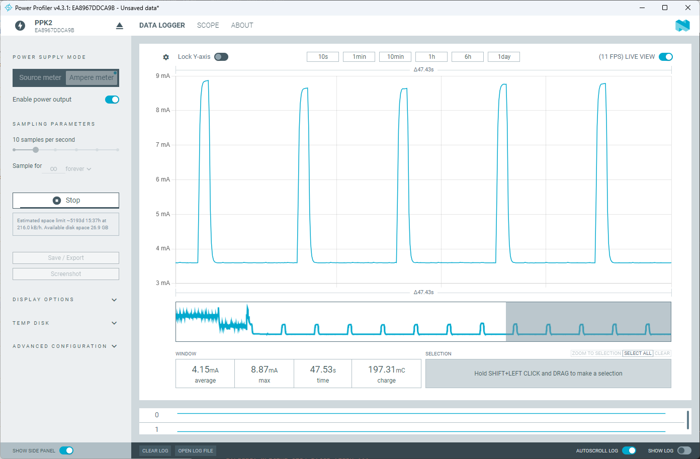
DISK ADVANCED CONFIGURATION WINDOW SELECTION ZOOM TO SELECTION SELECT ALL CLEAR 4.15mA average 8.87mA max 47.53s time 197.31mC charge Hold SHIFT+LEFT CLICK and DRAG to make a selection SHOW SIDE PANEL CLEAR LOG OPEN LOG FILE AUTOSCROLL LOG SHOW LOG
Max Drift, Max Supply Current 1.8mA per Op Amp LT1213/LT1214 Dual/Quad 28MHz, 12V/μs, Single Supply Precision Op Amps Input Common Mode Includes Ground, 275μV V OS(MAX), 6μV/°C Max Drift, Max Supply Current
horizontal) Material: GFR polyterephthalate, UL 94 V-0, insulation class to IEC 60085: B66359A/B: F max. operating temperature 155 °C, color code black ® Valox 420-SE0 E45329 (M) , SABIC INNOVATIVE PLASTICS B66359W: H max. operating temperature 180 °C, color code black Rynite FR 530 ® E41938 (M
Durchlassspannung 4)Seite 21 (min.) VF 2.7 V Forward voltage 4) page 21 (typ.) V 3.2 V F IF= 350 mA (max.) VF 3.7 V Sperrstrom not designed for Reverse current (max.) R reverse operation μA Wärmewiderstand Thermal resistance Sperrschicht/Lötpad (typ.) R 6.5 K/W th JS K/W Junction/soldering point (max.)
(0x0001) SCT Support Level: 0 Device State: Active (0) Current Temperature: 0 Celsius Power Cycle Max Temperature: 0 Celsius Lifetime Max Temperature: 0 Celsius SCT Temperature History Version: 2 Temperature Sampling Period: 10 minutes Temperature Logging Interval: 10 minutes Min/Max recommended Temperature: 0/70 Celsius Min/Max Temperature Limit: -5/75 Celsius Temperature History Size (Index): 478 (373) Index Estimated Time Temperature Celsius 374 2013-09-26 07:40 ? - ... ..(476 skipped). .. - 373 2013-09-29 15:10 ? - SCT
ICS VS= 2.7V to 5.5V, T A 25°C, unless otherwise noted. LTC1157C SYMBOL PARAMETER CONDITIONS MIN TYP MAX UNITS IQ Quiescent Current OFF V S 3.3V, VIN1= VIN2= 0V (Note 1) 3 10 A Quiescent Current ON V S 3.3V, VIN 3.3V (Note 2) 80 160 A V S= 5V, VIN 5V (Note 2) 180 400 A V INH Input High Voltage 70%× V S
MSA-series is fabricated using Avago’s 10 GHz • Tape-and-Reel Packaging Option Available fT, 25 GHz f MAX, silicon bipolar MMIC process which • Lead-free Option Available uses nitride self-alignment, ion implantation, and gold metallization to achieve excellent performance, uniformity and reliability.The
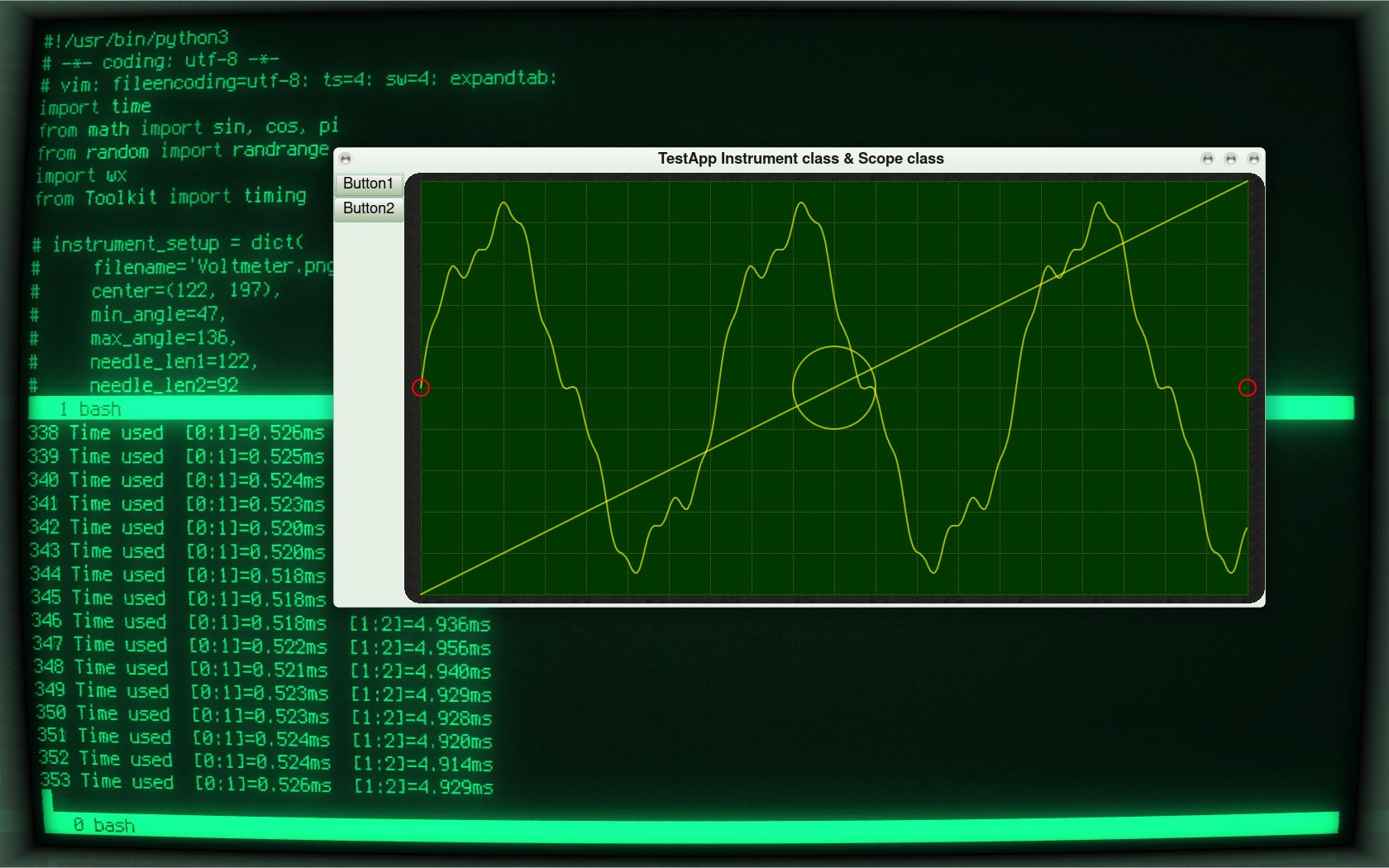
ux
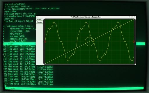
from Toolkit import timing
# instrument_setup = dict(
# filename='Voltmeter.png'
# center=(122, 197),
# min_angle=47,
# max_angle=136,
# needle_len1=122,
# needle_len2=92
#
338 Time used [0:1]=0.526ms
339 Time used [0:1]=0.525ms
340 Time used [0:1]=0.524ms
341 Time used [0:1]=0.523ms
342 Time used

 Bild
Bild
 Bild
Bild
 Bild
Bild
 Bild
Bild

 Bild
Bild