-
PDF
mcp3424.pdf
,U)O\LGG[RU%L\)RZLG(URNY32XR2O)Y3()R)3GU,LX\UNW J:21 JU&U,UX\UR'O8UXNO3X/R(N(LGG[R2O)Y3()R)3GU,LX\U/R&3,ROX&3,8L)O3XR0(,03NUNR3XG[W QO\,3\YO0 VU\YX3G3F[ ',L2OXF $5HPK+ © 2009 Microchip Technology Inc. DS22088C-page 41 MCP3422/3/4 /HDG3OVWL3F'X)V1R3LVNL3'JV0&VDG3OVW3
in „Sensorplatine MPX4115 DS1621 HIH5030 - Schaltungskontrolle“ · Mikrocontroller und Digitale Elektronik ·
-
Datei
tft.c
0x00000000 /* wallpaper 320x180, format = RGB565', total size = 115200 bytes */ #define MEM_FONT 0x000f7e00 /* the .xfont file for the UTF-8 font is copied here */ #define MEM_LOGO 0x000f8000 /* start-address of logo, needs 6272 bytes of memory */ #define MEM_PIC1 0x000fa000 /* start of 100x100 pixel test
-
PDF
ecp_ec.pdf
GND2 2 GND GND2 2 C22 NC - C22 PR9A 2 T RUM0_PLLT_FB_A C22 PR9A 2 T RUM0_PLLT_FB_A G19 NC - G19 PR8B 2 C RUM0_PLLC_IN_A G19 PR8B 2 C RUM0_PLLC_IN_A G18 NC - G18 PR8A 2 T RUM0_PLLT_IN_A G18 PR8A 2 T RUM0_PLLT_IN_A F20 NC - F20 PR7B 2 C F20 PR7B 2 C F19 NC - F19 PR7A 2 T F19 PR7A 2 T E20 NC - E20 PR6B
in „Verwendung der Pins eines Lattice LFECP6 mit Config-Dual-Funktion als I/Os“ · FPGA, VHDL & Co. ·
-
PDF
ecp_ec.pdf
GND2 2 GND GND2 2 C22 NC - C22 PR9A 2 T RUM0_PLLT_FB_A C22 PR9A 2 T RUM0_PLLT_FB_A G19 NC - G19 PR8B 2 C RUM0_PLLC_IN_A G19 PR8B 2 C RUM0_PLLC_IN_A G18 NC - G18 PR8A 2 T RUM0_PLLT_IN_A G18 PR8A 2 T RUM0_PLLT_IN_A F20 NC - F20 PR7B 2 C F20 PR7B 2 C F19 NC - F19 PR7A 2 T F19 PR7A 2 T E20 NC - E20 PR6B
in „SPI-Slave im FPGA, Signal-Delay an MISO minimieren“ · FPGA, VHDL & Co. ·
-
PDF
Clock_jitter_analyzed_in_the_Time_Domain_Part_2.pdf
JITTER FROM DEVICE 90-fs CLOCK JITTER WITH RF AMPLIFIER MEASURED SNR (dBFS) (dBFS) (fs) ADS54RF63 (f = 1 GHz) 59.9 60.0 ~85 IN ADS5483 (fIN= 100 MHz) 77.8 77.6 ~95 2 SNR 2 SNR 2 − Measured − − Thermal Nose 10 20 10 20 2 tJitter,Clock_Input= −(t Aperture_ADC ) (5) 2π×f IN
-
Datei
Problemkind.asm
list p=12F675 ; "list" Anweisung zur Definition des Prozessors #include <p12f675.inc> ; Einbinden von speziellen, zum Controller gehörenden Variablen über die Datei *.inc __CONFIG _CP_OFF & _WDT_OFF & _BODEN_ON
in „Phänomen bei PIC12F675 - ich versteh es nicht!“ · Mikrocontroller und Digitale Elektronik ·
-
PDF
Eng_ET-TFT240320TP-3.2.pdf
TFT240320TP 3.2 2 C 3 c 2 P r 7 T I 8 0 i 8 3 P 1 0 I 2 P T T U - C E M H 0 1 n a r t - n u P T JumpForMCU5V Figure4showsexampleofinterfacingBoardET TFT240320TP 3.2withMCUPIC#18F8722(5V). 3.2) If using with MCU 3.3V, please notice that Pin
in „LCD 240x320 color + touch screen module“ · Mikrocontroller und Digitale Elektronik ·
-
Datei
clock_16F88.ASM
!!! bcf EECON1,EEPGD ; !!! necessary for PIC16F88 !!! bsf EECON1, RD ; read character from EEProm banksel EEADR ; !!! necessary for PIC16F88 !!! incf EEADR,f ; inc address for next read movf EEDATA,w ; bsf STATUS,RP1 ; goto Bank2 bcf STATUS,RP0
in „Programm von Pic16F628 für Pic16F88 ändern“ · Mikrocontroller und Digitale Elektronik ·
-
PDF
0540_0549.pdf
, the solution and electrodes stay unchanged and the conductivity is accurately measured. Based on 8-bit Microchip PIC18F architecture [4], the devices use a cycle of alternated charging-discharging small capacitors. Threshold voltage detection and derived period of time is made using onboard CMOS trigger
in „einfacher Messverstärker für DC-Verstärkung“ · Analoge Elektronik und Schaltungstechnik ·
-
PDF
LS7366R.pdf
index coincident with both A and B low.. Note 3. f F is the internal effective filter clock . FIGURE 5. f CKI , A, B and INDEX 7366R-120407-8 DOWN UP DOWN B t6 t7 t8s t8H A t9s t9H CNT_EN FIGURE 6. COUNT (A) AND DIRECTION (B) INPUTS IN NON-QUADRATURE
in „Quadratur Counter SPI“ · Mikrocontroller und Digitale Elektronik ·
-
Datei
main-master.c
******************************************* copyright(c) 2010 Title: RFM70 simple example based on PIC c Current version: v1.0 Function: RFM70 demo processor: PIC16F690 Clock: 8M Crystal Author: baiguang(ISA) Company: Hope microelectronic Co.,Ltd. Contact: +86-0755-82973805-846 E-MAIL: rfeng@hoperf.com
in „Hat jemand Erfahrung mit dem 2,4GHz-Transceiver RFM70?“ · HF, Funk und Felder ·
-
Datei
main-slave.c
******************************************* copyright(c) 2010 Title: RFM70 simple example based on PIC c Current version: v1.0 Function: RFM70 demo processor: PIC16F690 Clock: 8M Crystal Author: baiguang(ISA) Company: Hope microelectronic Co.,Ltd. Contact: +86-0755-82973805-846 E-MAIL: rfeng@hoperf.com
in „Hat jemand Erfahrung mit dem 2,4GHz-Transceiver RFM70?“ · HF, Funk und Felder ·
-
PDF
FreqCounter16F628ALCDschematic.pdf
J1 D3 Q1(P) +5V 2 AP2530GY IN OUT Frequency Counter 1 BAT42 GND R10 IC3 9V 100k 78L05 with PIC16F628A D4 D5 RB5 DIYfan.blogspot.com C7 + C8 +C9 C10 Q1(N) 1N4148 1N4148 AP2530GY 1uF 100uF 100uF 1uF RB4 LCD1 +5V LCD DISPLAY 16x2 SW1 R11 ON/OFF 100k R8 T 20k N C O S / 0 1 2 3 4 5 6 7 + - G V C R R E D D D D D D D D B B GND GND 1 2 3 4 5 6 7 8 9 1 1 1 1 1 1 1 +5V R9 L1 IC2 PIC16F628A GND 2.2k* FB 1 RA2/AN2/VREF RA1/AN1 18 +5V +5V 2 RA3/AN3/CMP1 RA0/AN0 17 3 RA4/TOCKI/CMP2 RA7/OSC1/CLKIN 16 R3 R7 IC1 10k 10k 4 RA5/~MCLR/VPP RA6/OSC2/CLKOUT
in „Frequenzzähler mit PIC 16F628A“ · Mikrocontroller und Digitale Elektronik ·
-
PDF
Triac___Entstoerdrossel.pdf
V+ IC1 +12V Spannungsversorgung IN OUT µ D8 N + 0 10AT L1F BV EI 306 3601 n G n 1 F1 ~Br1 2 0 7812 3 0 2 1 F 1 D3 C 1 C 1 C K 5 C 4,7mH 2 C D1 LL4148 2 X 2 Y - F + 1 +12V V K 1 C IC2 R DF F + +5V V 1 2 C D4 D2 F 0 L1 2 Y D9 IN DOUT µ ~ B40C1500
in „Thyristordrossel Verbindung auf der Leiterplatte“ · Mikrocontroller und Digitale Elektronik ·
-
Datei
Rumpf_main.c
files //------------------------------------------------------------------------------ #include <p18cxxx.h> // Header file für alle PIC // Hier kann auch #include <p18F2550.h> bzw. <p18f4550.h> stehen. Mit 18cxxx nimmt der Compiler // das File, das zu dem µC passt, der unter Configure eingestellt ist
in „Mikrocontroller reagiert falsch“ · Mikrocontroller und Digitale Elektronik ·
-
PDF
MCP_2210.pdf
DS52056A-page 17 MCP2210 Breakout Module User’s Guide A.2 BOARD – SCHEMATIC D S n 5 M J U D - V D D I G B 8 7 6 O 5 K 1 2 3 4 5 U G G G I G S D M D D G D - + N _ D G 0 S B 6 5 U U 0 6 F C 1 D + - N D D B G B B U U U V D 0 9 8 7 6 5 4 3 2 1 2 1 1 1 1 1 1 1 1 1 N + D B P P P O P K G V D U G G G I G S 0 V M 1
in „USB - SPI Adapter“ · Mikrocontroller und Digitale Elektronik ·
-
PDF
AN2662-Sensorless-Drive-forSingle-and-Two-PhaseBLDC-Motor-00002662A.pdf
note desc®ibes how to implement a sensorless control for single and two-phase BLDC motors using the 8-bit PIC microcontroller. The implementation is based on the low-cost PIC16F153XX family of microcontrollers and hardware BEMF filtering in a cooling fan application. The application is tested on a 80
in „EBM-Papst EC Motor“ · Analoge Elektronik und Schaltungstechnik ·
-
PDF
AD5415.pdf
1k 10k 100k 1M 0 6 6 TIME (ns) 4 FREQUENCY (Hz) 4 0 0 Figure18.MidscaleTransition,V REF=0V Figure21.THDandNoisevs.Frequency –1.68 100 T = 25°C 7FF TO 800H A –1.69 VREF = 3.5V MCLK = 1MHz VDD = 5V AD8038 AMPLIFIER C COMP = 1.8pF 80 –1.70 ) ( –1.71 E G ) 60 MCLK =
in „D/A mit Stromausgang“ · Mikrocontroller und Digitale Elektronik ·
-
Datei
irmp-libopencm3.diff
irmpsystem.h index 25bacb2..e1fbc97 100644 --- a/irmpsystem.h +++ b/irmpsystem.h @@ -26,6 +26,9 @@ # define PIC_C18 #elif defined(__PCM__) || defined(__PCB__) || defined(__PCH__) // CCS PIC compiler # define PIC_CCS +#elif defined(STM32F1) // ARM STM32 with libopencm3 +# define ARM_OPENCM3 +# define F_CPU (SysCtlClockGet
in „IRMP - Infrared Multi Protocol Decoder“ · Projekte & Code ·
-
 Bild
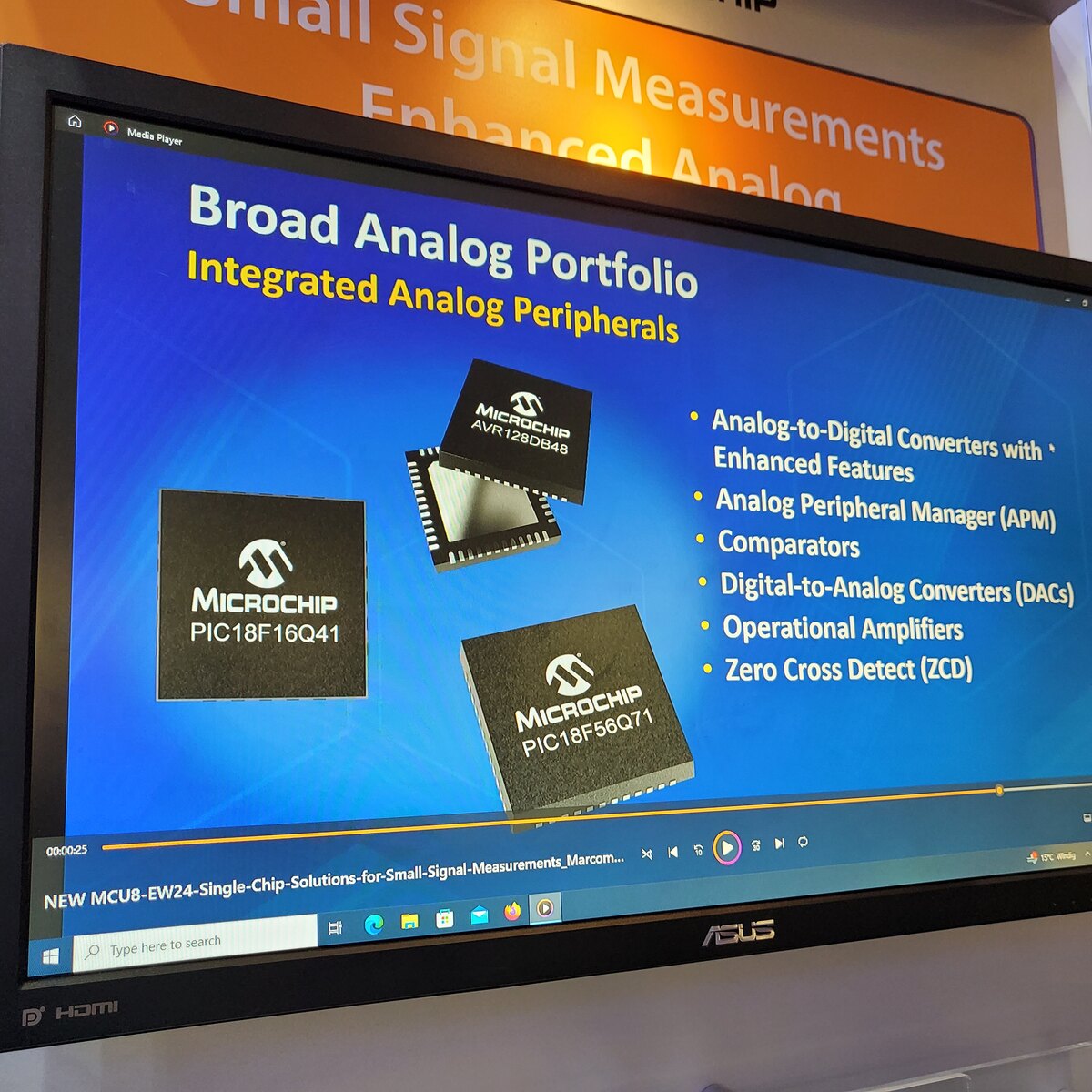
Präsentation von Microchip Analog-Peripheriegeräten auf Monitor
Comparators Digital-to-Analog Converters (DACs) Operational Amplifiers Zero Cross Detect (ZCD) MICROCHIP PIC18F16Q41 MICROCHIP PIC18F56Q71 NEW MCU8-EW24-Single-Chip-Solutions-for-Small-Signal-Measurements_Marcom...
in „Embedded World 2024 - mehr Chips, Software uvam“ · Mikrocontroller und Digitale Elektronik · · Fotos
-
PDF
PIC_Grafik_Board_PCB.pdf
C6 C12 C11 1F PFC8583T 47µF 150µF C13 IC1 150µF 0 R R R k 1k8 8 1 1 R14R13R12 P4 3k3k33k3 a P3 C MMC-Card-Slot S 10k 10k LCD GLCD 1 GND S2 1 X 1 2 3 1 SG1 X + UBatt 2 D 4 2 1 2 +5V 3 4 1 Summer GND 1 RESET AN_0 4 X 2 U$1 AN_1 Grün 1 C18 1 6 0 1µF F AN_2 5 X 2 PIC18F458-E/PT 1µF X1 RS232 AN_3 470RR8 1 LED3 C16 AN_4 Q1 ROT 1µF 5 9 X 2 C17 C32 36MHz 1µF AN_5 1 100nF 2,54 AN_6 7 S_6 S_7 S_8 C2 1 X 2 1 1 1 R15 100nF 0 AN_7 C1 2 2 2 1k8 X
in „Verkaufe PIC Grafik Board“ · Markt ·
-
PDF
WT588D-U_Voice_Module.pdf
BUSY 8.2.6、Models of Procedure Master SCM:PIC16F54,Clock frequency :4MHz Send one-line (unsigned char addr) { sda=0; delay1ms(5); /* Data signals at low level 5ms */ for(i=0;i<8;i++) { sda=1; if(addr & 1) -
in „WT588D Voice Modul Tonqualität“ · Analoge Elektronik und Schaltungstechnik ·
-
PDF
MCP3221.pdf
(f SAMP = 22.3 ksps), T =A+25°C. 3 2 1.8 ) 2 ) 1.6 B S L 1 VDD= 2.7V ( 1.4 r r 1.2 VDD= 5V o 0 r 1 E E n e 0.8 a-1 f 0.6 G O -2 0.4 VDD= 5V 0.2 VDD= 2.7V -3 0 -50 -25 0 25 50 75 100 125 -50 -25 0 25 50
in „Suche Bauteilbezeichnung 5-Pin SOT-23 mit "S1SD" Marking“ · Mikrocontroller und Digitale Elektronik ·
-
PDF
schematics.pdf
P0 PC120p P26n8 TC2117-3.3VDBTR GND 5V P1 Pk c 5R19 0R21 b P0 P1 P2 U3 V_SUPPLY d 817 F 1 PI U30 1 RT_CLK SS_TR PIU30 56 e P0 PI U30 2 COMP EN_BUCK PIU30 55 e PI U30 3 VSENSE PVDD2 PIU30 54 PC9PIC929 GND n PI U30 4 PWRGD PVDD2 PIU30 53 10µ L1 5V C PCOR PI U30 5 OCTW BST_BK PIU30 52 PC7PIC72 PIL 101 P IL10 2 k 318 P OFAULT LT PI U30 6 PIU30 51 100nF 22uH u P0 PR0 P21 PI U30 7 FAULT PH PIU30 50 P0 P3 P0 B R20 10k 8 DTC PH 49 CR25 CO33 PI U39 8 M_PWM BIAS PI480 49 P21M P20 C28 GND P0D4
in „BLDC Motorcontroller 200A 48V basierend auf VESC“ · Analoge Elektronik und Schaltungstechnik ·
-
Datei
scope.c
);NOP();NOP();NOP();NOP();NOP();NOP();NOP();NOP(); RES_H(); //Charge Pump Setting OLED_Send_Comm(0x8d); OLED_Send_Comm(0x14); OLED_Send_Comm(0xaf); //Set Display Clock OLED_Send_Comm(0xD5); OLED_Send_Comm(0xF0); //Set Pre-charge Period OLED_Send_Comm(0xD9); OLED_Send_Comm(0x11); //Set VCOMH Deselect
in „XMega ADC gesamten SampleVector auf einmal einlesen“ · Mikrocontroller und Digitale Elektronik ·
-
PDF
SC16A_User_s_Manual.pdf
Channels 14 6. Installation (software) 16 6.1 Sample Program for Computer 16 6.2 Sample Program for PIC16F877A 20 7. Getting Started 21 7.1 Using SC16A with Computer 21 7.2 Using SC16A with Microcontroller 21 7.3 Protocol for SC16A 23 8. Warranty (6 months) 25 Created by Cytron Technologies Sdn. Bhd.
in „Servomotor Steuerung per PIC“ · Mikrocontroller und Digitale Elektronik ·
-
Datei
18F876_Int_PORTB_Change_01.ASM
Interrupt" NOLIST ;******************************************************************** ; Filename: 18F876_Int_PORTB_Change_01.ASM ; Author: GroberKlotz ; Date: 2012.04.13 ; IDE: MPLAB 8.92 ; Version: 00 ; 01 2015.06.22 Test mit 16F876-ob's noch funktioniert ; damit keiner im Forum meckert ;******************************************************************** ; Files: P16F876A.INC ; HD44780.INC ; ; Hardw.: PIC 16F876A ; Quarzosz. 4MHz ; ;******************************************************************** ; Projekt ; Auslösen des Change-Interrupts an PORTB,RB7:4 mittels
in „PIC16f887 PORTB Interrupt funktioniert nicht“ · Mikrocontroller und Digitale Elektronik ·
-
PDF
MCP2551.pdf
,6 N NOTE 1 E1 3 1 2 D E A2 A A1 L c e b1 eB b 6,KN& 57;8:Y 3K8\,&KH,09K8KN& R57 7:R RG; 7(8+\70H)0ZK,& 7 < ZKNSQ \ DEFF01Y; JHO0NH0Y\WNK,60Z'W,\ G = = DLEF RH'<\<0ZWS4W6\0JQKS4,\&& GL DEEP DE±F DEXP 1W&\0NH0Y\WNK,60Z'W,\ GE DFEP = = YQH('<\70NH0YQH('<\70>K
in „MCP2551 Standby Mode wenn AVR im Power down Modus“ · Mikrocontroller und Digitale Elektronik ·
-
Datei
frq_intrc.asm
************************************* ; ; Ausgangsprojekt von: ; sprut (zero) Bredendiek 11/2001 ; 8-stelliger Frequenzzhler mit LCD-Display ; http://www.sprut.de/electronic/pic/projekte/frequenz/freq.htm ; ; angepasst für PIC16F628a mit internen RC-Takt und ; Messung ohne Vorteiler ; ; Prozessor-Takt
in „Frequenzzähler 1Hz-100khZ“ · Mikrocontroller und Digitale Elektronik ·
-
PDF
schaltplan.pdf
_B 11 18 100nF LED3_G 12 RC0/P2B RX1/DT1/AN19/RC7 17 G1 13 RC1/P2A TX1/P3A/AN18/RC6 16 GND 4 2 0 LED3_R 14 RC2/AN14/P1A SDO1/AN17/RC5 15 SWITCH_2 BUCHS_3_ABGEW GND 3 R 1 RC3/AN15/SCK1/SCL1 SDI1/SDA1/AN16/RC4 POTI 1 LED2_B R14 2 POTI PIC18F26K22SO28W 2 1 SWITCH_2 3 R15 LED2_R JP1 JP3 R16 GND GND LED2_G R17 LED3_G GND R18 C LED3_R C R19 V LED3_B R20 LED4_R GND R21 LED4_G PIS2812 R22 LED4_B IC2 L1 1 SW VIN 6 GND 2 GND VOUT 5 3 FB SHDN
-
PDF
Platte_neu_2.pdf
20 RD1/SPP1 RD2/SPP2 21 DB6 3 GND 8 RD7 2 +5V PIC18F4455_40 74HC08N 2 7 +15V_T2 R8 T2 T6 3 6 -15V MOSFET +15V 8 k 0 k BC337 10R C22 +C21 16 15 2 0 3 0 PWM 4 IC2B 5 C7 + C4 DC3 14 13 R 1 R 1 6 R33 2 GND_T2 47u _ 24 1 +VIN +VOUT 11 14 100n GND_T2 2,5 V because pos. and neg. currrent 12 11 w 2 0 3 0 RD6 5 10k TLP250F D 100n 47u COM 10 15 R18 / R17 are a voltage divieder 10 9 o R 1 R 1 74HC08N N 13 12 -VIN COM 3 22 1 R GND 8 7 T4 l OP_3_LOW_SIDE_LEFT G -VOUT 2 23 C24 +C23 R 3 GND 6 5 T3 u +15V GND_T2 4 3 T2 x GND
in „Schaltung H-Brücke mit µC und Zubehör“ · Mikrocontroller und Digitale Elektronik ·
-
PDF
A4964JPDemoR0.pdf
OSCO CBUS1 PI1322 PIU306 RC4 RC1 PIU309 CBUS2 PI1413 7 8 SDI_F D 1 2 3 T CBUS3 PI4014 PIU307 RC3 RC2 PIU308 PIU017 3V3OUT G N N N S CBUS4 PI4012 D PI A G G G T E C3 PIC16F1825 D CC7 TITLEA4964JP Customer Demonstration Board (QFP32) 100n 5 7 8 1 6 PI2 10V P
in „Allegro A4964 Demoboard - ein Phantom?“ · Analoge Elektronik und Schaltungstechnik ·
-
Datei
main.c
/ PIC32MM MCUs - 1.170.0 Device : PIC24F16KM202 The generated drivers are tested against the following: Compiler : XC16 v1.61 MPLAB : MPLAB X v5.45 */ /* (c) 2020 Microchip Technology Inc. and its subsidiaries
in „PIC24F16KM202 RA4 und RB4 nicht als Ausgang nutzbar“ · Mikrocontroller und Digitale Elektronik ·
-
PDF
USB_HFE_Messger_t.pdf
15 D- 16 220nF VSS GND 3 R PIC18F2553 8 1 1 0 GND +5V/1 R 1 S D U D V GND D D V G GND USB GND N C CINT +5V/1 PWS1 V V+ D 2 E+ A+ 4 D1 +9V D V 1N4007 IC3 V 1 E- A- 3 5 TRIM V-OUT 6 IN OUT 3 +C2 C3 GND TME0512 GND 1 2 GND IC5 3 NC V-IN IC2 220uF 100nF IC DS18S20 7 NC 7805 + 8 NC 4 1 A D2 NC GND B GND USB HFE Messgerät - BAT43 REF01HP T GND GND REV 3 B GND
in „Transistortester auf PIC Basis mit USB“ · Mikrocontroller und Digitale Elektronik ·
-
 Bild
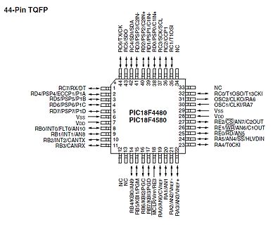
Pinbelegung PIC18F4480 und PIC18F4580 TQFP
44-Pin TQFP PIC18F4480 PIC18F4580 RC6/TXCK RC5/SDA RD3/PSP3/C2IN RD2/PSP2/C2IN+ RD1/PSP1/C1IN+ RC2/SCK/SCL RC1/T1OSI NC RC0/T1OSO/T13CKI OSC2/CLKO/RA6 OSC1/CLKI/RA7 VDD Vss RE2/CS/AN7/C2OUT RE1/WBR/AN6/C1OUT RE0/RD
in „Ansteuerung einer Anzeigetafel - Federal Vama Traffic Storm“ · Fahrzeugelektronik · · Screenshots
-
PDF
BitTiming.pdf
Quanta 20 % Error of Target Baud Rate 0,0 % Bit Timing Setup in Tq Propagation Delay 3 Phase Segment 1 8 Phase Segment 2 8 Syncronization Jump Width (SJW) 1 Multiple bit sampling is off. Wakeup filter is off. Bit Timing Diagram Configuration Register Setup (PIC18/MCP251X) (neoVI blue/green, ValueCAN 2)
in „Pic18F4680 CAN-Bus Baudrate“ · Mikrocontroller und Digitale Elektronik ·
-
PDF
Forum.PDF
2 P2 PIu_hub P10 R5_ ub SRN4018-4R7M HUB1V8 U1_hubB 100k 1% 1206 GND GND PI1hb1 PI1hb11 Place 4.7uF by LAN954-38 PI1hb3 VDD18CORE VBUS_DET C 48 840buh01UIP C PI1hb6 VDD18ETHPLL PI10u0 VDD18USBPLL b HUB3V3A PI1hb1 VDD33A +3.3 COL0ub HUB3V3A b 6
in „Raspberry Pi Compute Module 3 (Carrier Board)“ · Mikrocontroller und Digitale Elektronik ·
-
Datei
xlcd.txt
/* $Id: openxlcd.c,v 1.1 2003/12/09 22:52:09 GrosbaJ Exp $ */ #include "p18F4580.h" #include "delays.h" /* PIC18 XLCD peripheral routines. * * Notes: * - These libraries routines are written to support the * Hitachi HD44780 LCD controller. * - The user must define the following
-
PDF
311_Schaltungen.pdf
funktioniert das beschriebene Prinzip trollevonAufbauundLötstellendurchge- mit SO-Gehäusen. Bei SO-8-Gehäusen führt werden. kann man sogar auf den Lackdraht ver- zichten und die Verbindung vom IC-Pin 101 Break-out-Board für PIC10F2xx (SOT23-6) Luc Lemmens (Elektor-Labor) Mikrocontrollergibtesindenunterschied
in „[S] Sammlung von elektr. Schaltungen“ · Mikrocontroller und Digitale Elektronik ·
-
PDF
ET-TFT240320TP-3_2RevB_Eng_.pdf
ifMCUthatisconnectedhasnotanypinthatisOpenDrain,itneednottoconnectRPullUp. VCC+5V +3V3 J1(Header2x20) GND 1 Vref +5V 2 VDDA LCDCS H 3 P1.18 VDD2 RS H 5 P1.19 VDD3 WRD H 6 P1.21 RES H 8 P1.22 22K BL H P1.23 DB0 H 10 P0.8 RESET DB2 H 11 P0.10 DB3 H 13 P0.11 0.1uF DB4 H 14 P0.12 DB6 H 15 P0.14 DB7 H 16 P0.15 22pF DB8 H 18 P0.16 XTAL1 DB10 H
in „TFT ILI9341 SPI modus ohne D/C pin HILFE!“ · Mikrocontroller und Digitale Elektronik ·
-
PDF
Datenlogger_V1.pdf
In 0 P RN1E 4k7 Array S VCC C8 8 0 IC2 GND P 0,1uF a P GND 1 1 a a 0 P P S s P C10 C k k IC3 C 5 0 4 0 B R 1 R 1 I/O10 44I/O 0 470nF S Sup 0 Pas 0 1 1 RC7/RX/DT/SDO RC6/TX/CK 1 U 1 P P I/O20 RD4/SPP4 RC5/D+/VP 43I/O 0 P V Pas 0 2
in „Datenlogger mit PIC18F“ · Mikrocontroller und Digitale Elektronik ·
-
Datei
ServoPWM.asm
f goto $+2 decfsz g4, f goto Warten_18.834_0 ;2 cycles goto $+1 ;4 cycles (including call) return Warten_1.249 ;1243 cycles movlw 0xF8 movwf h1 movlw 0x01 movwf h2 Warten_1.249_0 decfsz h1, f goto $+2
in „PIC16F628A PWM mit delay (ASM)“ · Mikrocontroller und Digitale Elektronik ·
-
PDF
mcp6004.pdf
and therefore outside the warranted range. Note: Unless otherwise indicated, T A = +25°C, V DD = +1.8V to +5.5V, V SS = GND, V CM = V DD /2, V OUT ≈ V DD /2, R L 10 kΩ to V DD /2, and C = L0 pF. 22% 100 s 1225 Samples c 20% VCM= VSS n 18% e 16% B u ( 90 c 14% R O 12% R PSRR (V = V ) f M CM SS o 10% ,
in „Nichtinvertierender Operationsverstärker“ · Analoge Elektronik und Schaltungstechnik ·
-
Datei
lcd.c
0x7c, 0x38, 0x7c, 0xc6, 0xc6, 0xc6, 0x00, 0x00}, { 0x00, 0x00, 0x00, 0x66, 0x66, 0x66, 0x66, 0x3c, 0x18, 0x18, 0x18, 0x3c, 0x00, 0x00}, { 0x00, 0x00, 0x00, 0xfe, 0xc6, 0x8c, 0x18, 0x30, 0x60, 0xc2, 0xc6, 0xfe, 0x00, 0x00},// Z { 0x00, 0x00, 0x00, 0x3c, 0x30, 0x30, 0x30, 0x30, 0x30, 0x30, 0x30, 0x3c, 0x00
in „Spielereien mit dem LPC-P2148“ · Mikrocontroller und Digitale Elektronik ·
-
Datei
TECHLIB_APR07_Dir.txt
644P_D0207.pdf 12.03.2007 16:38 340.615 m164P_324P_644P_D0207s.pdf 12.03.2007 16:38 3.148.587 m165_F0806.pdf 12.03.2007 16:38 239.127 m165_F0806s.pdf 12.03.2007 16:38 3.368.486 m165P_H1106.pdf 12.03.2007 16:38 281.796 m165P_H1106s.pdf 12.03.2007 16:38 3.388.558 m169_P0706.pdf 12.03.2007 16:38 295.634
in „STK500 CD ISO Image“ · Mikrocontroller und Digitale Elektronik ·
-
PDF
EjN-ST-A10_LIUST-5X_CustomerDisplay.pdf
Code xx yy(Shift-JIS KANJI CODE) (Pf=3,5) Pd…Pd Font Data xx (00-FF) *Valid / -Invalid 16x16 Font 15 8 0 0 Byte (00) 1 Byte (00) 15 2 Byte (3F) 3 Byte (FE) 4 Byte (02) 5 Byte (20) 6 Byte (02) 7 Byte (20) 8 Byte (02) 9 Byte (20) 10 Byte (1F) 11 Byte (FC) 12 Byte (12) 13 Byte (24) 8 14 Byte (12) 15 Byte
in „Hat schon jemand was mit dem FUJITSU VF60 Display gemacht?“ · Mikrocontroller und Digitale Elektronik ·