of wires Lead spacing e ±0.4 Lead diameter d 1±0.05 Type 2-pin 27.5 0.8 B32714H 2-pin 37.5 1.0 B32716H 4-pin 37.5 1.2 B32716H 4-pin 52.5 1.2 B32718H Dimensions in mm Dimensional drawings 2-pin versions B32714H, B32716H B32714H B32716H Lead spacing e ±0.4: 27.5 37.5 Lead diameter d : 0.8 1.0 1 Dimensions in mm B32716H (low profile) Lead spacing e ±0.4: 37.5 Lead diameter d 1: 1.0 Dimensions in mm Please read Cautions and warnings and Important notes
es <100ms ist, die 5V durch großen Elko puffern und die 5V überwachen. Mittels Analogeingang oder 4,9V Schwellwertschalter oder Brown Out Detektor. Da der MC sicher bei <4,9V noch funktioniert, bleibt die notwendige Zeit. 2) Das Netzteil mittels Taster einschalten, der MC aktiviert ein Relais (oder
E M — -0.2 ±0.5 % Dynamic Performance 10 kHz Sine Wave Input 1dB below full scale, VREF = 2.4 V Signal-to-Noise SNR 55 58 — dB Signal-to-Noise Plus DistortioSNDR 55 58 — dB Total Harmonic Distortion (Up
Adam P. schrieb im Beitrag #7843910: > Muss nicht 100% genau sein, ich denke mal so 2-4% Genauigkeit. > Temperatur wird wohl so zwischen 20°C - 50°C liegen. Die mittlere Temperatur läge dann bei grob 300K, so dass du mit 2-4% bei Abweichungen von bis zu 12K landest. Hört sich machbar
würde ich lieber PT1000 verwenden, wenn das Gerät sehr lange halten soll. Die NTCs entwickeln nach m.E. nach >10 Jahren doch eine merkliche Drift.
einem STM32U0 verwendet. 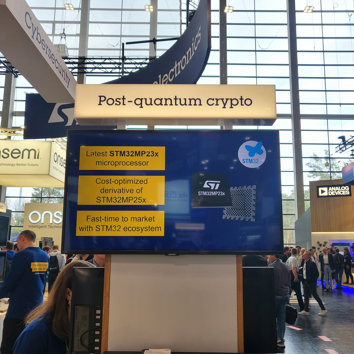 ### Espressif – QWERTZ-Tablet mit ESP32-P4, PLCs, ESP32-H4-Demo Espressif zeigte sich in Sachen Neuankündigungen gar nicht faul. Eine Demo des H4 bewies, dass es sich dabei nicht um Vaporware handelt. 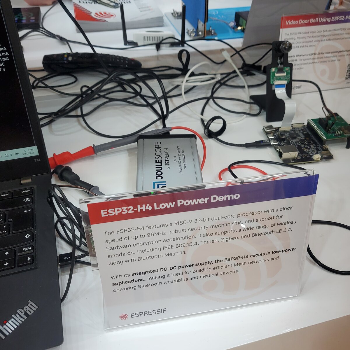 Der
Shutdown Current vs Junction IN IN Temperature 50 1.09 VO = 1.05 V 45 1.08 40 35 A ) 1.07 ( ( n 30 e r t u 25 o 1.06 t t p p I 20 u E O 15 1.05 10 1.04 5 VIN= 5 V VIN= 12 V VIN = 12 V VIN= 18 V 0 1.03 0 5 10 15 20 0 0.5 1 1.5 2 2.5 3 3.5 4 4.5 5 5.5 EN Input Voltage (V) Output Current (A) G002 G004
DIMENSIONS (inch dimensions are derived from the original mm dimensions) UNIT A A1 A 2 A3 bp c D(1) E(2) e H E L Lp Q v w y Z(1) max. mm 1.75 0.25 1.45 0.25 0.49 0.25 5.0 4.0 1.27 6.2 1.05 1.0 0.7 0.25 0.25 0.1 0.7 0.10 1.25 0.36 0.19 4.8 3.8 5.8 0.4 0.6 0.3 8o 0.010 0.057 0.019 0.0100 0.20 0.16 0.244
Microsystems Plc 3 D/602B/2 Calling Line Identifier CMX602B 1.3 Signal List Packages Signal Description D4/P3/E4 Pin No. Name Type 1 XTALN O/P The output of the on-chip Xtal oscillator inverter. 2 XTAL I/P The input to the on-chip Xtal oscillator inverter. 3 RD I/P (S) Input to the Ring or Line Polarity Reversal
ziemlich sinnlos. Die sollte auch mehr als ein paar Minuten überbrücken. Mit einem uC, TCXO und u-blox SAM-10Q reicht eine 18650-Zelle für viele Stunden, das sollte noch passen. Mit 4 NOR-Flash Speicherchips braucht der uC kaum RAM und man kann 127 Tage lang jeden Tag 2MByte Rohdaten speichern. Oder ein
Low Distortion Oscillat...........................................................................4...................... 4 High Voltage AC Calibrato.........................................................................5...................... 5 Negative Resistance Oscillat.......................
Low Distortion Oscillat...........................................................................4...................... 4 High Voltage AC Calibrato.........................................................................5...................... 5 Negative Resistance Oscillat.......................
C) Figure 1. On−Region Characteristics Figure 2. Gate−Threshold Voltage Variation With Temperature E A 20 L 2 25°C V N ) W VGS = 0 S 16 TJ= −55°C D 1.6 M 100°C A ID= 0.25 mA ( E ) N 12 B E1.2 R C L R R A C O R I 8 − ON0.8 R T ( , N ID VDS = 20 V A 4 D 0.4 ,) S 0 ( 0 0 4 8 12 16 20 B −50 −75 0 25 50
惠州市惠城区潼侨镇宏村宏川路鑫永诚科技园 2/9 电话(Tel):0752—7987222 网址(Web site):http//www.xycgd.com 传真(Fax):0752—7987000 邮箱(E-mail):@xycgd.com PIR 系列 XYC-PIR223D-S0 最大额定值 Maximum Ratings 参 数 符号 最小值 最大值 单位 备注 Parameter Symbol min max unit note 供电电压 Input voltage V DD -0.3 4.5 V 管脚电流 Pin current nto -100 100 mA 储存温度 Tst -40 85
dann auch nicht wirklich Wie schon zuvor zitiert: 5V/max 700mA Schlimm hoch gerundet im Schnitt 3-4W. Sagen wir 4. Etwa 35kWh/a. Ich habe da schon schlimmere Verbraucher gesehen.
Stromverbrauch als ein NUC, passiv gekühlt, RAM / SSD aufrüstbar, .... Been there, done that. Pi4B -> Wyse5070 -> NUC8i5 Der Stromverbrauch im Leerlauf ist beim NUC8 nicht höher als beim Wyse 5070, und beide brauchen weniger als der Pi4B mit SSD. Dafür laufen auf dem NUC unter Proxmox halt
ISINK = 3.2mA 0.4 MAX69_AC, MAX802_C, V = 1.0V RESET Output Voltage CC 0.3 V ISINK = 50μA MAX69_AE/M, MAX802_E, 0.3 V CC = 1.2V,SINK = 100μA MAX805LC, I SOURCE = 4μA, VCC = 1.1V 0.8 MAX805LE/M, I = 4μA, V = 1.2V 0.9 RESET
gehangen habe. Meine Überlegung war angehangene Schaltung mit BC337-40, GND = das gesteuerte PWM Signal, R4 = 1000 Ohm, Spule Relais hat etwa 80 Ohm, Freilauf und Z Diode (12V). Steuereingang = Vcc = ~12V -14V Verstärkungsfaktor und Ströme passen, ich weiß nur nicht bei welcher Potentialdifferenz Basis/Emitter
das Relais aus sein [pre] +12V +12V | | 47uF | | |E --|<|--+--1k--|< PNP BC327 1N4148 | +---+---+ _|_ | 1N4148 /_\ Relais | | Masse Masse [/pre] Aber die Schaltung ist auch nicht
values. 003aaa037 10 003aaa038 1 I ITSM T(RMS) T (A) ITSM 0.8 (A) 8 T time o 6 Tjinitial = 25 C max 0.6 4 0.4 0.2 2 0 0 0 20 40 60 80 100 120 140 1 10 102 n 103 o Tlead ( C) n = number of cycles at f = 50 Hz Fig 4. Maximum permissible non-repetitive peak Fig 5. Maximum permissible RMS current as a on-state
dortige Angabe von "Line" musst du 16 aufaddieren: https://onlinedocs.microchip.com/oxy/GUID-F5813793-E016-46F5-A9E2-718D8BCED496-en-US-14/GUID-DA8CB38A-18D7-4512-965B-BB439142B281.html Heißt also, IPSR=16 ist PM - Power Manager Interrupt, IPSR=17 ist MCLK - Main Clock usw. Alex schrieb im Beitrag
. Alex schrieb im Beitrag #7832315: > Nur wie schaltet man das Recording ein? Siehe Kapitel 4.19 der zuvor verlinkten Anleitung.
XLamp LEDS: Information and Cautions 20101215 CLD-AP60 PulseCurrent.docx 140 ) / 120 ( y 100 i 80 f e 60 u i 40 m 20 L 0 0 500 1000 1500 2000 2500 Forward current (mA) 5% 20% 50% Figure 3: XLamp XP-E Luminous Efficiency vs. Input Current [R4 bin] 4 Figure 3: XLamp XP-E luminous effici n y vs. input current
A U Shelf life (at 105 C) After 1000 hours no load test, leakage current, capacitance and tan are same as load life value. R E T DRAWING Unit : mm Y P E S Insulating sleeve d 0.05 Tinned copper-ply wire x D 5 6.3 8 10 12.5 16 18 22 25.4 m P 2.0 2.5 3.5 5.0 5.0 7.5 7.5 10.0 12.5 . P 0.5 0 d 0.5 0.5 0.6
Asterisk konfiguriert wird: [code] [dtmf_menu] exten => s,1,Noop(answer a call to our menu) same => n,Answer() same => 10,Background(hello) same => n,WaitExten(60) exten => 1234,1,Noop(Number entered successfully) same => n,Playback(activated) same => n,System(/usr/bin/switch_relay) same => n,Playback(goodbye) same => n,Hangup() exten => i,1,Noop(Invalid number entered, retry) same => n,Playback(please-try-again) same => n,Goto(s,10) exten => t,1,Noop(Timeout) same
gezeigten Aufbau, der die einzelnen Kameramodule „modular“ zusammenstellt.  Bildquelle: https://www.ifixit.com/News/108201/galaxy-s25-ultra-teardown-quick-battery-fix-slow-progress-on-repairability Sinn dieser auf den ersten Blick für höhere Interconnect-Kosten
nRF-basierten Mikrocontrollern verwenden: [c] If you want to use a Zephyr-supported BLE device (e.g. nRF51/52) as a custom Find My Device tracker, you can find the firmware in the folder ZephyrFirmware. [/c] In der Beschreibung des Repositoriums weist der Autor darauf hin, dass es sich dabei
Speaker Header (Pins 1-3: Power LED, Pins 6-7: Internal 1. Always use DDR3 SO-DIMM modules of the same type, size, and speed. e n - - u i T T Buzzer, Pins 4-7: External Speaker) Mixing memory modules of different types and speeds is not allowed. t , 3 2 o e O JF1 Front Control Panel Header i e 2 Battery
axis, select the maximum load current, I (Max) = 0.4 A. LOAD Identify the inductance region intersected by the E × T value and the maximum load current value, and note the inductor value for that region, inductance region = 1000. Select an appropriate
Function 1 VSS 0v Ground 2 VDD 5.0v Supply Voltage for Logic 3 V O (variable) Supply Voltage for LCD 4 RS H/L H: Data L: Instruction Code H: Read 5 R/W H/L L: Write 6 E H, H L Chip Enable Signal 7 DB0 H/L Data Bus Line 8 DB1 H/L Data Bus Line 9 DB2 H/L Data Bus Line 10 DB3 H/L Data Bus Line 11 DB4 H/L
A A A V S CS index area 2 2 2 2 2 1 LED0 1 18 RESET LED1 2 17 LED15 LED2 3 16 LED14 PCA9532BS LED3 4 15 LED13 LED4 5 14 LED12 LED5 6 13 LED11 7 8 9 1 1 1 6 7 S 8 9 1 E DE V E DE D 002aae520 L L L L L Transparent top view Fig 4. Pin configuration for HVQFN24 PCA9532 All information provided in this document
. min. max. b b 1 b2 c D E e e1 L ME M H w max. mm 1.73 0.53 1.25 0.36 19.50 6.48 3.60 8.25 10.0 4.2 0.51 3.2 1.30 0.38 0.85 0.23 18.55 6.20 2.54 7.62 3.05 7.80 8.3 0.254 0.76 inches 0.068 0.021 0.049 0.014 0.77 0.26 0.14 0.32
DIMENSIONS (inch dimensions are derived from the original mm dimensions) UNIT A A1 A 2 A3 bp c D(1) E(2) e H E L Lp Q v w y Z(1) max. mm 1.75 0.25 1.45 0.25 0.49 0.25 5.0 4.0 1.27 6.2 1.05 1.0 0.7 0.25 0.25 0.1 0.7 0.10 1.25 0.36 0.19 4.8 3.8 5.8 0.4 0.6 0.3 8o 0.010 0.057 0.019 0.0100 0.20 0.16 0.244
W (2–30) C IC 10 mA V V V R E R E1) R E2+ E + E ^ E + 4 V + 400 W (2–31) IE IB) IC IC 10 mA Use Thevenin’s equivalent circuit to calc1late 2 and R as shown in Figure 2–16. R1|| 2 IB R2 V = 4.6 V 12 R1+ R2 B Figure 2–16. Thevenin
LINE/SWITCHER 9 10 OV DELAY SENSE SENSE 1 NC 6 16 POWER OK SENSE 4 INVERT 7 15 UV DELAY INPUT SENSE 4 8 14 UV FAULT 9 10 11 12 13 3 2 1 E E E A L S S S E AU E E E D F S S S V V O O ABSOLUTE MAXIMUM RATINGS (1) over operating free-air temperature range (unless otherwise
E M — -0.2 ±0.5 % Dynamic Performance 10 kHz Sine Wave Input 1dB below full scale, VREF = 2.4 V Signal-to-Noise SNR 55 58 — dB Signal-to-Noise Plus DistortioSNDR 55 58 — dB Total Harmonic Distortion (Up
device. The EMXO offers low-phase noise at 10 Hz < -120 dBc/Hz and Allan Deviation (ADEV) stability <1E-11 at a 1-second averaging time. The atomic clock provides initial accuracy of ±0.5 ppb, low frequency drift performance of <0.9 ppb/mo, and maximum temperature-induced errors of < ±0.3ppb. Together,
to operate for up to ten years on a single coin cell battery. The BG22L also supports Bluetooth 5.4 and Bluetooth Direction Finding. It features an ARM Cortex M33 processor at 38.4 MHz, up to 352 kB of flash, and up to 24 kB of RAM in a 4 mm x 4 mm QFN32 packaging. [/c] Die Auslieferung der Halbleiter
#7821181: > Dort werden nur 3 Pins verwendet. Bei Canon sieht es nicht anders aus: - Akku LP-E100 besitzt 4 Anschlüsse - Canon Battery Charger LC-E10E kontaktiert alle 4 Pins - Kamera verwendet 3 davon
#7821181: >> Dort werden nur 3 Pins verwendet. > > Bei Canon sieht es nicht anders aus: > - Akku LP-E100 besitzt 4 Anschlüsse > - Canon Battery Charger LC-E10E kontaktiert alle 4 Pins > - Kamera verwendet 3 davon Dann ist es für mich klar. Wenn der Charger 4 Pins verwendet, dann um die Spannung
problems unless the ILI9341 data sheet has been understood! Updated by Bodmer 21/12/16 for TFT_eSPI library: https://github.com/Bodmer/TFT_eSPI BSD license applies, all text above must be included in any redistribution *************************************************************/ #include <TFT_eSPI.h> // Hardware-specific library #include <SPI.h> TFT_eSPI tft = TFT_eSPI(); // Invoke custom library // The scrolling area must be a integral multiple of TEXT_HEIGHT #define TEXT_HEIGHT
ohne Masken aber mit Mikro-Spiegel-Projektor und Optiken Belichtungen bis zu 10 µm Auflösung (Angabe Sam Zeloof) hinbekommt: https://www.youtube.com/watch?v=XVoldtNpIzI Chips mit ~1000 Transistoren sind wohl so machbar: http://sam.zeloof.xyz/second-ic/ Auch Golem hat schon davon berichtet:
darf natürlich Jeri Ellsworth nicht unerwähnt bleiben: https://www.youtube.com/watch?v=MxjppY1iA4A&list=PL5DCEA197C1C07A2D
mA 1.5 V Saturation Voltage LED = 2.0 mA, L(REF)= 0.4 mA 0.15 0.4 V (4) Output Leakage, Each Collector (Bar Mode) 0.1 10 μA Output Leakage (Dot Mode) (4) Pins 10–18 0.1 10 μA Pin 1 60 150 450 μA SUPPLY CURRENT Standby Supply Current V = +5V, I = 0.2 mA
Motor Back Electromagnetic Force (BEMF)..............................................................4 3. BEMF Filtering...........................................................................................................6 4. Motor Prepositioning and Start-up.....................................
SLLSEY2G – MARCH 2017 – REVISED AUGUST 2021 ) 5.14 130 800 ( g ) 125 700 l A o 5.09 ( ) y n 120 600 W p e ( u u r S C 115 500 w e 5.04 l o o p 110 400 t P u u u t i t u 105 300 C O 4.99 i r d C h t r 100 200 S o h I S 95 100 4.94 Short-circuit Supply Current -40 -20 0 20 40 60 80 100 120 Short-circuit Power
