-
Datei
mcp23017_2.c
innerhalb der I2C-Unterprogramme aus und ein. extern uint8_t wort_a; //---------------------------MCP23017---I2C---------------------------------------- #include "ST7920.h" //für DG14032 //#define MCP23017_adress1 0x24 //MCP23017 0100 100 nur A2 an high #define MCP23017_adress1 0x48 //MCP23017 0010 010
in „I2C - Pull Up Widerstände“ · Mikrocontroller und Digitale Elektronik ·
-
Datei
LiquidTWI2.h
0x0A #define MCP23017_GPPUA 0x0C #define MCP23017_INTFA 0x0E #define MCP23017_INTCAPA 0x10 #define MCP23017_GPIOA 0x12 #define MCP23017_OLATA 0x14 #define MCP23017_IODIRB 0x01 #define MCP23017_IPOLB 0x03 #define MCP23017_GPINTENB 0x05 #define MCP23017_DEFVALB 0x07 #define MCP23017_INTCONB 0x09 #define MCP23017_IOCONB 0x0B #define MCP23017_GPPUB 0x0D #define MCP23017_INTFB 0x0F #define MCP23017_INTCAPB 0x11 #define MCP23017_GPIOB 0x13 #define MCP23017
in „LCD STN 320x240 große Schrift 16x24 / 20x10 ATmega8 Assembler TWI USART inkl. Fontgenerator VBA“ · Projekte & Code ·
-
Datei
channel.h
_GPPUA 0x0C #define MCP23017_INTFA 0x0E #define MCP23017_INTCAPA 0x10 #define MCP23017_GPIOA 0x12 #define MCP23017_OLATA 0x14 #define MCP23017_IODIRB 0x01 #define MCP23017_IPOLB 0x03 #define MCP23017_GPINTENB 0x05 #define MCP23017_DEFVALB 0x07 #define MCP23017_INTCONB 0x09 #define MCP23017_IOCONB 0x0B #define MCP23017_GPPUB 0x0D #define MCP23017_INTFB 0x0F #define MCP23017_INTCAPB 0x11 #define MCP23017_GPIOB 0x13 #define MCP23017_OLATB 0x15 #define MCP23017
in „ATtiny85 und MCP23017 liefert NACK“ · Mikrocontroller und Digitale Elektronik ·
-
PDF
MCP2307_IO_Expansion_Board_User_Manual_EN.pdf
MCP23017 IO Expansion Board MCP23017 IO Expansion Board User Manual OVERVIEW This is an I/O expansion module uses I2C interface, gives you 16 GPIO. Supports using 8 expansion modules at the same for up to
in „kennt jemand sich aus mit MC23017 IO-Board“ · Mikrocontroller und Digitale Elektronik ·
-
PDF
MCP23017-Datasheet.pdf
Stop W - Write R - Read OP - Device opcode ADDR - Device register address DOUT - Data out from MCP23017 DIN - Data in to MCP23017 2005-2016 Microchip Technology Inc. DS20001952C-page 13 MCP23017/MCP23S17 2 3.2.2.2 I C Read Operation I C Read operations include the control byte sequence, as shown in
in „kennt jemand sich aus mit MC23017 IO-Board“ · Mikrocontroller und Digitale Elektronik ·
-
Datei
kklcdxx.c
lcdbyte); hwSpiA(0x12,lcdbyte+WERTpinE); hwSpiA(0x12,lcdbyte); #endif #if use_twilcd72 //uint8_t mcp23017_72_A,mcp23017_72_B; //lcdbyte d7-d6-d5-d4-en-rs-//-// mcp23017_72_A= (mcp23017_72_A & 0b00000011) + (lcdbyte & 0b11111100); //mcp23017_72_B= (mcp23017_72_B & 0b00111111) + (((lcdbyte & 0b00000100)<<5)); set_mcp23017_outAB(mcp23017_72_A, mcp23017_72_B); set_mcp23017_outAB((mcp23017_72_A + WERTpinE), mcp23017_72_B ); set_mcp23017_outAB(mcp23017_72_A, mcp23017_72_B); #endif #if use_twilcd72x set_mcp23017_outAB(lcdbyte
in „I2C LCD mit Raspberry“ · Mikrocontroller und Digitale Elektronik ·
-
Datei
kklcdxx.c
lcdbyte); hwSpiA(0x12,lcdbyte+WERTpinE); hwSpiA(0x12,lcdbyte); #endif #if use_twilcd72 //uint8_t mcp23017_72_A,mcp23017_72_B; //lcdbyte d7-d6-d5-d4-en-rs-//-// mcp23017_72_A= (mcp23017_72_A & 0b00000011) + (lcdbyte & 0b11111100); //mcp23017_72_B= (mcp23017_72_B & 0b00111111) + (((lcdbyte & 0b00000100)<<5)); set_mcp23017_outAB(mcp23017_72_A, mcp23017_72_B); set_mcp23017_outAB((mcp23017_72_A + WERTpinE), mcp23017_72_B ); set_mcp23017_outAB(mcp23017_72_A, mcp23017_72_B); #endif #if use_twilcd72x set_mcp23017_outAB(lcdbyte
in „Verzweiflung um LCD Lib von Peter Fleury“ · Mikrocontroller und Digitale Elektronik ·
-
Datei
MCP23017_LIB.c
(!) } void mcp23017_clear_all_outputs(uint8_t i2c_address) { mcp23017_write_gpio_a(i2c_address, 0x00); mcp23017_write_gpio_b(i2c_address, 0x00); } void mcp23017_drive_output(uint8_t i2c_address, uint8_t output_no) //output_no 1..16 { if (output_no <= 8) // I/O BANK_A { mcp23017_write_gpio_b(i2c_address, 0x00); mcp23017_write_gpio_a(i2c_address, 1<<(output_no-1)); } else if (output_no <=16) // I/O BANK_B { output_no -= 9; mcp23017_write_gpio_a(i2c_address, 0x00); mcp23017
in „MCP23017 funktioniert erst wie er soll nach Reset des µC“ · Mikrocontroller und Digitale Elektronik ·
-
Datei
Programm.txt
delay_ms(1000); // Nach der Initialisierung warten // ############################################### MCP23017 initialisieren ############################################## Soft_I2C_Start(); // Issue start signal Soft_I2C_Write(0x40); // Address MCP23017 schreiben ==> Soft_I2C_Write(IOCON); // Address MCP23017
in „ATMega32 liest über I2C-Bus die Eingänge vom MCP23017“ · Mikrocontroller und Digitale Elektronik ·
-
Datei
Programm.txt
delay_ms(1000); // Nach der Initialisierung warten // ############################################### MCP23017 initialisieren ############################################## Soft_I2C_Start(); // Issue start signal Soft_I2C_Write(0x40); // Address MCP23017 schreiben ==> Soft_I2C_Write(IOCON); // Address MCP23017
in „ATMega32 liest über I2C-Bus die Eingänge vom MCP23017“ · Mikrocontroller und Digitale Elektronik ·
-
Datei
channel.c
); i2c_stop(); // set all to 0 i2c_start(MCP23017_ADR + I2C_WRITE); i2c_write(MCP23017_OLATA); i2c_write(0x00); i2c_stop(); // Port B as output i2c_start(MCP23017_ADR + I2C_WRITE); i2c_write(MCP23017_IODIRB); i2c_write(0x00); i2c_stop(); // set all to 0 i2c_start(MCP23017_ADR + I2C_WRITE); i2c_write(MCP23017_OLATB); i2c_write(0x00); i2c_stop(); }
in „ATtiny85 und MCP23017 liefert NACK“ · Mikrocontroller und Digitale Elektronik ·
-
Datei
Adafruit_CharLCDPlate.py
--------------------------------------------------------- # Constants # Port expander registers MCP23017_IOCON_BANK0 = 0x0A # IOCON when Bank 0 active MCP23017_IOCON_BANK1 = 0x15 # IOCON when Bank 1 active # These are register addresses when in Bank 1 only: MCP23017_GPIOA = 0x09 MCP23017_IODIRB = 0x10
in „ATmega32 - LCD mit Adafruit Breakout - Code portieren“ · Mikrocontroller und Digitale Elektronik ·
-
PDF
Rollladensteuerung.pdf
Atmega16 HMI Über TWI angesteuert Über TWI angesteuert Wallbutton UP MCP23017 (Input) MCP23017 (Input) Wallbutton Down Aktoren MCP23017 (Output) PortA2, Port B und Port D RTC Über TWI angesteuert Über TWI angesteuert Weitere Erläuterungen beziehen sich auf die aktuell gepflegte
-
Datei
Loesung.txt
Soft_I2C_Write(0x41); // Addrese MCP23017 lesen ==> PortF := Soft_I2C_Read(0); // Lesen der Eingänge des MCP23017 Soft_I2C_Stop(); // Issue stop signal delay_ms(500); Soft_I2C_Start(); // Issue start signal Soft_I2C_Write(0x40); // Adresse MCP23017 schreiben ==> Soft_I2C_Write(OLATA); // Adresse auf GPIOB setzen Soft_I2C_Write(PortF); // gelesene Daten von PortB des MCP23017 an PortA des MCP23017 ausgeben Soft_I2C_Stop(); // Issue stop signal
in „ATMega32 liest über I2C-Bus die Eingänge vom MCP23017“ · Mikrocontroller und Digitale Elektronik ·
-
PDF
Rollladensteuerung.pdf
Atmega16 HMI Über TWI angesteuert Über TWI angesteuert Wallbutton UP MCP23017 (Input) MCP23017 (Input) Wallbutton Down Aktoren MCP23017 (Output) PortA2, Port B und Port D RTC Über TWI angesteuert Über TWI angesteuert Weitere Erläuterungen beziehen sich auf die aktuell gepflegte
-
PDF
Rollladensteuerung.pdf
Atmega16 HMI Über TWI angesteuert Über TWI angesteuert Wallbutton UP MCP23017 (Input) MCP23017 (Input) Wallbutton Down Aktoren MCP23017 (Output) PortA2, Port B und Port D RTC Über TWI angesteuert Über TWI angesteuert Weitere Erläuterungen beziehen sich auf die aktuell gepflegte
-
PDF
Rollladensteuerung.pdf
Atmega16 HMI Über TWI angesteuert Über TWI angesteuert Wallbutton UP MCP23017 (Input) MCP23017 (Input) Wallbutton Down Aktoren MCP23017 (Output) PortA2, Port B und Port D RTC Über TWI angesteuert Über TWI angesteuert Weitere Erläuterungen beziehen sich auf die aktuell gepflegte
-
Datei
MCP23017.h
/* * MCP23017.h * * Created: 02.02.2015 19:06:45 * Author: Stephan */ #ifndef MCP23017_H_ #define MCP23017_H_ #define IODIRA 0x00 #define IODIRB 0x01 #define IOPOLA 0x02 #define IOPOLB 0x03 #define GPINTENA 0x04
in „Probleme beim auslesen des MCP23017“ · Mikrocontroller und Digitale Elektronik ·
-
Datei
functions.c
ZIMbedarfCtrl=ZIMbedarf; //wait10; for(i=3;i<6;i++) { if(!gbi(ZimAbwesend,i)){maskeZIM[i]='x';}} //mcp23017_72_B= (mcp23017_72_B & 0b11000000) + (ZIMbedarf & 0b00111111); //if(mcp23017gefunden==0){set_mcp23017_out(72,0x13,mcp23017_72_B);} } } #ifndef LaufzeitH volatile u8 LaufzeitH; #endif void lcd_anzeige
in „Heizungssteuerung Wärmepumpe Fußbodenheizung“ · Mikrocontroller und Digitale Elektronik ·
-
Datei
main.c
#define F_CPU 8000000UL #include <avr/io.h> #include "MCP23017_LIB.h" #include <util/delay.h> int main(void) { _delay_ms(500); mcp23017_init(0x4e); while (1) { for (int i=1; i<=16; i++) { mcp23017_drive_output(0x4e, i); _delay_ms(20); } mcp23017_clear_all_outputs
in „MCP23017 funktioniert erst wie er soll nach Reset des µC“ · Mikrocontroller und Digitale Elektronik ·
-
Datei
MCP23017.c
/* * MCP23017.c * * Created: 04.02.2015 19:12:51 * Author: Stephan */ #include <stdint.h> #include "TWI_Master.h" #include "MCP23017.h" uint8_t MCP23017_readByte(uint8_t SlaveAddress,uint8_t RegisterAddress){ uint8
in „Probleme beim auslesen des MCP23017“ · Mikrocontroller und Digitale Elektronik ·
-
Datei
lcd_routines.h
die 4 // Datenleitungen müssen auf aufeinanderfolgenden Pins liegen //Adresse des Slave Devices MCP23017 //Die ersten 4 Bit sind laut Datenblatt definiert(0100) //Die letzten 3 Bit werden über die Pins A0-A2 definiert #define SLAVE 0b0100000 // LCD DB4-DB7 <--> PORTB an MCP23017 Bit GPB1-GPB4 #define LCD_PORT 0x13 //GPIOB Register Addresse des MCP23017 #define LCD_DDR 0x01 // IODIRB Register addresse des MCP23017 #define LCD_DB 1 // GPB1 // LCD RS <--> PORTD Bit PD4 (RS: 1=Data, 0=Command) #define LCD_RS 7 // LCD EN <--> PORTD Bit PD5 (EN: 1-Impuls
in „LCD ansteuerung mit einem ATMega16 und I2C“ · Mikrocontroller und Digitale Elektronik ·
-
Datei
lcd-routines.h
die 4 // Datenleitungen müssen auf aufeinanderfolgenden Pins liegen //Adresse des Slave Devices MCP23017 //Die ersten 4 Bit sind laut Datenblatt definiert(0100) //Die letzten 3 Bit werden über die Pins A0-A2 definiert #define SLAVE 0b0100000 // LCD DB4-DB7 <--> PORTB an MCP23017 Bit GPB1-GPB4 #define LCD_PORT 0x13 //GPIOB Register Addresse des MCP23017 #define LCD_DDR 0x01 // IODIRB Register addresse des MCP23017 #define LCD_DB 1 // GPB1 // LCD RS <--> PORTD Bit PD4 (RS: 1=Data, 0=Command) #define LCD_RS 7 // LCD EN <--> PORTD Bit PD5 (EN: 1-Impuls
in „LCD ansteuerung mit einem ATMega16 und I2C“ · Mikrocontroller und Digitale Elektronik ·
-
Datei
lcd-routines.h
die 4 // Datenleitungen müssen auf aufeinanderfolgenden Pins liegen //Adresse des Slave Devices MCP23017 //Die ersten 4 Bit sind laut Datenblatt definiert(0100) //Die letzten 3 Bit werden über die Pins A0-A2 definiert #define SLAVE 0b0100000 // LCD DB4-DB7 <--> PORTB an MCP23017 Bit GPB1-GPB4 #define LCD_PORT 0x13 //GPIOB Register Addresse des MCP23017 #define LCD_DDR 0x01 // IODIRB Register addresse des MCP23017 #define LCD_DB 1 // GPB1 // LCD RS <--> PORTB BIT GPIOB7 (RS: 1=Data, 0=Command) #define LCD_RS 7 // LCD EN <--> PORTB BIT GPIOB5 (EN:
in „LCD ansteuerung mit einem ATMega16 und I2C“ · Mikrocontroller und Digitale Elektronik ·
-
Datei
Functions.ino
address+2, u.b[2]); EEPROM.write(address+3, u.b[3]); } //THESE FUNCTIONS WILL TURN THE PINS OF A MCP23017 ON AND OFF. THIS ALLOWS FOR THE CONTROL OF UP TO 16 MACHINES. //EVEN MORE MACHINES COULD BE CONTROLLED BY ADDING MORE MCP23017s, BUT THIS CODE WOULD HAVE TO BE MODIFIED. void turnMCP23017PinOn(int
in „Heliostatensteuerung mit Arduino Uno“ · Mikrocontroller und Digitale Elektronik ·
-
Datei
MCP23017.h
#ifndef mcp23017_H_ #define mcp23017_H_ #define I2C_Slave_Adresse 0x40 #define I2C_Slave_Lesen 1 #define I2C_Slave_Schreiben 0 #define IODIRA 0x00 #define IODIRB 0x01 #define IPOLA 0x02 #define IPOLB 0x03 #define
in „I2C - Pull Up Widerstände“ · Mikrocontroller und Digitale Elektronik ·
-
PDF
flipdot_neu_Register.pdf
Oben 74HC138D SET Ziffer SET Ziffer 7 Y7 G2B 5 D Ziffer 6 9 Y6 G2A 4 N 10 6 G 11 Y5 G1 Enable PortA7 MCP23017 Flipdot Display 12 Y4 13 Y3 3 Y2 C 14 Y1 B 2 6 Ziffern Ziffer 05 Y0 A 1 r ffi IC2 Z Ziffernauswah 0-6 V a 5x3 Dots 5 + 74HC574D 1 OC 1 74HC221D R 4075D 13 11 15 10 12 CLK 4 R/C 14 11 12 9 Q C C1 8Q 8D
in „Flipdot Display Projekt (Hilfe Logik Erbeten)“ · Mikrocontroller und Digitale Elektronik ·
-
Datei
MCP23017.asm
define MCP_HAEN 1 ;HardwareAdressEnable 1=Aktiviert AdressPins 0=Deaktiviert AdressPins ( Nicht für MCP23017 ) #define MCP_DISSLW 0 ;SlewRateControl 1=Langsame geschwindigkeit aus 0=Langsame Geschwindigkeit an #define MCP_SEQOP 0 ;Sequentielle Operations Mode 1=AdressPointer geht nicht von allein weiter
in „MCP23017 Assembler Initialisierung“ · Mikrocontroller und Digitale Elektronik ·
-
Datei
MCP23017.PAS
{ *** *** Exerciser for I2C GPIO chip MCP23017 *** *** Martin Hepperle, 2018 *** } Program MCP23017; Const I2C_BASE = $60; _IODIRA = $00; _IODIRB = $01; _IPOLA = $02; _IPOLB = $03; _GPPUA = $0C; _GPPUB = $0D; _GPIOA = $12; _GPIOB = $13; _OLATA
in „CP/M auf ATmega88“ · Mikrocontroller und Digitale Elektronik ·
-
PDF
SNET-System.pdf
Rolladen Motoren SNET-Relais_32 CAN-Controller r r r r r c k k c c Arduino Nano C t C t C t C t MCP23017 C t I S I S MCP23017 I S I S I S 2 x x 2 2 2 2 DC/DC Step Down SNET1 SNET2 2x3 Stecker 2x3 Stecker 24V ETH Reserve L2 SNET-MQTT-Gateway Rolladen Motoren CAN-Controller W P CAT 5 (ohne Schirm) Arduino
in „Auf der Zielgeraden gescheitert (MCP23017 mit Relaiskarte instabil)“ · Mikrocontroller und Digitale Elektronik ·
-
PDF
MCP23017-IO-Expansion-Board-Schematic.pdf
RESET PIU1017A2 VCPIH201 1 SDAD PIU1013L A2PIU1016A1 1 Header 10 PIU10NCA A0PIU1015A0 Header 10 MCP23017 VCC VCC B P2O1 VCC P0 B R2R P100nF 1CR1 RESETP110K 100K P0O2 GND L1 P100nF PWR LED GND VCC L2 R2 P42 VCC VCC VCC H3H R3R R4R H4H GND PIH301C 10K 10K PIH401C 1 PIH302D R1 P41 1 PIH402D C 3 PIH303 SDA
in „kennt jemand sich aus mit MC23017 IO-Board“ · Mikrocontroller und Digitale Elektronik ·
-
PDF
testboard_05_00.sch.pdf
GPB1 2 GPB2 3 15 A0 GPB3 4 16 A1 GPB4 5 17 A2 GPB5 6 GPB6 7 10 VSS GPB7 8 0 0 0 0 0 2 0 4 0 6 0 MCP23017_1MM 2 5 4 5 6 5 8 5 1 5 1 5 1 5 1 5 GND R 1 R 1 R 1 R 1 R 1 R 1 R 1 R 1 1 2 3 4 5 6 7 8 9 1 1 1 1 1 1 1 VCC Button control D D D D D D D D D D D D D D D D IC2 L L L L L L L L L L L L L L L L 9 21
in „Zusatzplatine mit 4x4 Leucht-Tastern für Arduino-Neueinsteiger“ · Offtopic ·
-
PDF
Schematic_SIMInterface-Base_Schaltplan_20190313164157.pdf
123 4 5789 111111 111 +5V A A LED1 LTST-C155KGJRKT C5 +5V R5 100nF 330 U1 +5V ATMEGA32U4-AU U3 MCP23017T-ESS Buttons 1-16 330 42 AREF PF0 (ADC0) 41 J1 R4 PF1 (ADC1) 40 12 SCL GPA0 21 Header_Male_2x16 copy C6 2 UVcc PF4 (ADC4TCK) 39 13 SDA GPA1 22 16 32 1uF +5V PF5 (ADC5TMS)) 38 Connector for GPA2 23
in „ATMEGA32U4 Schaltplan“ · Mikrocontroller und Digitale Elektronik ·
-
PDF
raffstorecontrol.pdf
1,3 inch OLED 100nF 1 I1 O1 18 1 GND J5 U9 2 17 2 2 3 3 Conn_01x04 GND U8 I2 O2 3.3V 4 PC817 9 MCP23017 3 I3 O3 16 3 1 4 4 15 4 In1 D1 A I4 O4 1 A SDA 13 SDA D GPB0 1 5 I5 O5 14 5 J1 R1 2.2k 2 3 12 V 2 6 13 6 10K R5 GND GND SCL SCK GPB1 I6 O6 SW4 GPB2 3 7 I7 O7 12 7 4 8 N 11 8 hoch GPB3 5 I8 G O8 9
in „mcp23017 pull up / Vorwiderstand erforderlich?“ · Mikrocontroller und Digitale Elektronik ·
-
PDF
raffstorecontrol.pdf
SCL 2 1,3 inch OLED 100nF 1 I1 O1 18 1 GND J5 U9 2 17 2 3 Conn_01x04 GND U8 I2 O2 3.3V 4 PC817 9 MCP23017 3 I3 O3 16 3 1 4 4 15 4 In1 D1 A I4 O4 A SDA 13 SDA D GPB0 1 5 I5 O5 14 5 J1 Q3 2.2k 2 3 12 V 2 6 13 6 IRLML 6402 R5 GND GND SCL SCK GPB1 I6 O6 SW4 GPB2 3 7 I7 O7 12 7 D S 4 8 N 11 8 hoch GPB3 5 I8
in „mcp23017 pull up / Vorwiderstand erforderlich?“ · Mikrocontroller und Digitale Elektronik ·
-
Datei
FlipDot.ino
********************************************************/ #include <Wire.h> #include "Adafruit_MCP23017.h" Adafruit_MCP23017 mcp; // die Zeichenkodierung uint8_t hex2dot[][5] = { {0x7, 0x5, 0x5, 0x5, 0x7}, // 0 {0x2, 0x2, 0x2, 0x2, 0x2}, // 1 {0x7, 0x1, 0x7, 0x4, 0x7}, // 2 {0x7, 0x1, 0x3, 0x1, 0x7}
in „Flipdot Display Projekt (Hilfe Logik Erbeten)“ · Mikrocontroller und Digitale Elektronik ·
-
Datei
FlipDot.ino
********************************************************/ #include <Wire.h> #include "Adafruit_MCP23017.h" Adafruit_MCP23017 mcp; // die Zeichenkodierung uint8_t hex2dot[][5] = { {0x7, 0x5, 0x5, 0x5, 0x7}, // 0 {0x2, 0x2, 0x2, 0x2, 0x2}, // 1 {0x7, 0x1, 0x7, 0x4, 0x7}, // 2 {0x7, 0x1, 0x3, 0x1, 0x7}
in „Flipdot Display Projekt (Hilfe Logik Erbeten)“ · Mikrocontroller und Digitale Elektronik ·
-
Datei
FlipDot_02.ino
********************************************************/ #include <Wire.h> #include "Adafruit_MCP23017.h" Adafruit_MCP23017 mcp; // die Zeichenkodierung uint8_t hex2dot[][5] = { {0x7, 0x5, 0x5, 0x5, 0x7}, // 0 {0x2, 0x2, 0x2, 0x2, 0x2}, // 1 {0x7, 0x1, 0x7, 0x4, 0x7}, // 2 {0x7, 0x1, 0x3, 0x1, 0x7}
in „Flipdot Display Projekt (Hilfe Logik Erbeten)“ · Mikrocontroller und Digitale Elektronik ·
-
Datei
mcp_flipdot_v3.ino
********************************************************/ #include <Wire.h> #include "Adafruit_MCP23017.h" Adafruit_MCP23017 mcp; // die Zeichenkodierung uint8_t hex2dot[][5] = { {0x07, 0x05, 0x05, 0x05, 0x07}, // 0 {0x02, 0x02, 0x02, 0x02, 0x02}, // 1 {0x07, 0x01, 0x07, 0x04, 0x07}, // 2 {0x07, 0x01
in „Flipdot Display Projekt (Hilfe Logik Erbeten)“ · Mikrocontroller und Digitale Elektronik ·
-
Datei
mcp_first_test2.ino
********************************************************/ #include <Wire.h> #include "Adafruit_MCP23017.h" Adafruit_MCP23017 mcp; // die Zeichenkodierung uint8_t hex2dot[][5] = { {0x7, 0x5, 0x5, 0x5, 0x7}, // 0 {0x2, 0x2, 0x2, 0x2, 0x2}, // 1 {0x7, 0x1, 0x7, 0x4, 0x7}, // 2 {0x7, 0x1, 0x3, 0x1, 0x7}
in „Flipdot Display Projekt (Hilfe Logik Erbeten)“ · Mikrocontroller und Digitale Elektronik ·
-
Datei
mcp_flipdot_v3.ino
********************************************************/ #include <Wire.h> #include "Adafruit_MCP23017.h" Adafruit_MCP23017 mcp; // die Zeichenkodierung uint8_t hex2dot[][5] = { {0x07, 0x05, 0x05, 0x05, 0x07}, // 0 {0x02, 0x02, 0x02, 0x02, 0x02}, // 1 {0x07, 0x01, 0x07, 0x04, 0x07}, // 2 {0x07, 0x01
in „Flipdot Display Projekt (Hilfe Logik Erbeten)“ · Mikrocontroller und Digitale Elektronik ·
-
Datei
FlipDot_V04.ino
********************************************************/ #include <Wire.h> #include "Adafruit_MCP23017.h" Adafruit_MCP23017 mcp; // die Zeichenkodierung uint8_t hex2dot[][5] = { {0x07, 0x05, 0x05, 0x05, 0x07}, // 0 {0x02, 0x02, 0x02, 0x02, 0x02}, // 1 {0x07, 0x01, 0x07, 0x04, 0x07}, // 2 {0x07, 0x01
in „Flipdot Display Projekt (Hilfe Logik Erbeten)“ · Mikrocontroller und Digitale Elektronik ·
-
Datei
mcp_flipdot_hc05.ino
********************************************************/ #include <Wire.h> #include "Adafruit_MCP23017.h" Adafruit_MCP23017 mcp; // die Zeichenkodierung uint8_t hex2dot[][5] = { {0x07, 0x05, 0x05, 0x05, 0x07}, // 0 {0x01, 0x01, 0x01, 0x01, 0x01}, // 1 {0x07, 0x01, 0x07, 0x04, 0x07}, // 2 {0x07, 0x01
in „Flipdot Display Projekt (Hilfe Logik Erbeten)“ · Mikrocontroller und Digitale Elektronik ·
-
Datei
mcp_flipdot_v5.ino
********************************************************/ #include <Wire.h> #include "Adafruit_MCP23017.h" Adafruit_MCP23017 mcp; // die Zeichenkodierung uint8_t hex2dot[][5] = { {0x07, 0x05, 0x05, 0x05, 0x07}, // 0 {0x02, 0x02, 0x02, 0x02, 0x02}, // 1 {0x07, 0x01, 0x07, 0x04, 0x07}, // 2 {0x07, 0x01
in „Flipdot Display Projekt (Hilfe Logik Erbeten)“ · Mikrocontroller und Digitale Elektronik ·
-
PDF
A-4_MCP23017.pdf
.18,0m PA3 PA4 28AWG0,08mm²,15cm NYM-J3x1,5Max.18,0m 28AWG0,08mm²,15cm NYM-J3x1,5Max.18,0m WaveshareMCP23017 PA5 PA6 28AWG0,08mm²,15cm NYM-J3x1,5Max.18,0m PA7 Max.150mA PB0 28AWG0,08mm²,15cm NYM-J3x1,5Max.10,0m 28AWG0,08mm²,15cm NYM-J3x1,5Max.8,0m PB1 28AWG0,08mm²,15cm NYM-J3x1,5Max.8,0m PB2 28AWG0,08mm²,15cm
in „MCP23017 friert ein, stürzt ab“ · Mikrocontroller und Digitale Elektronik ·
-
 Bild
Bild
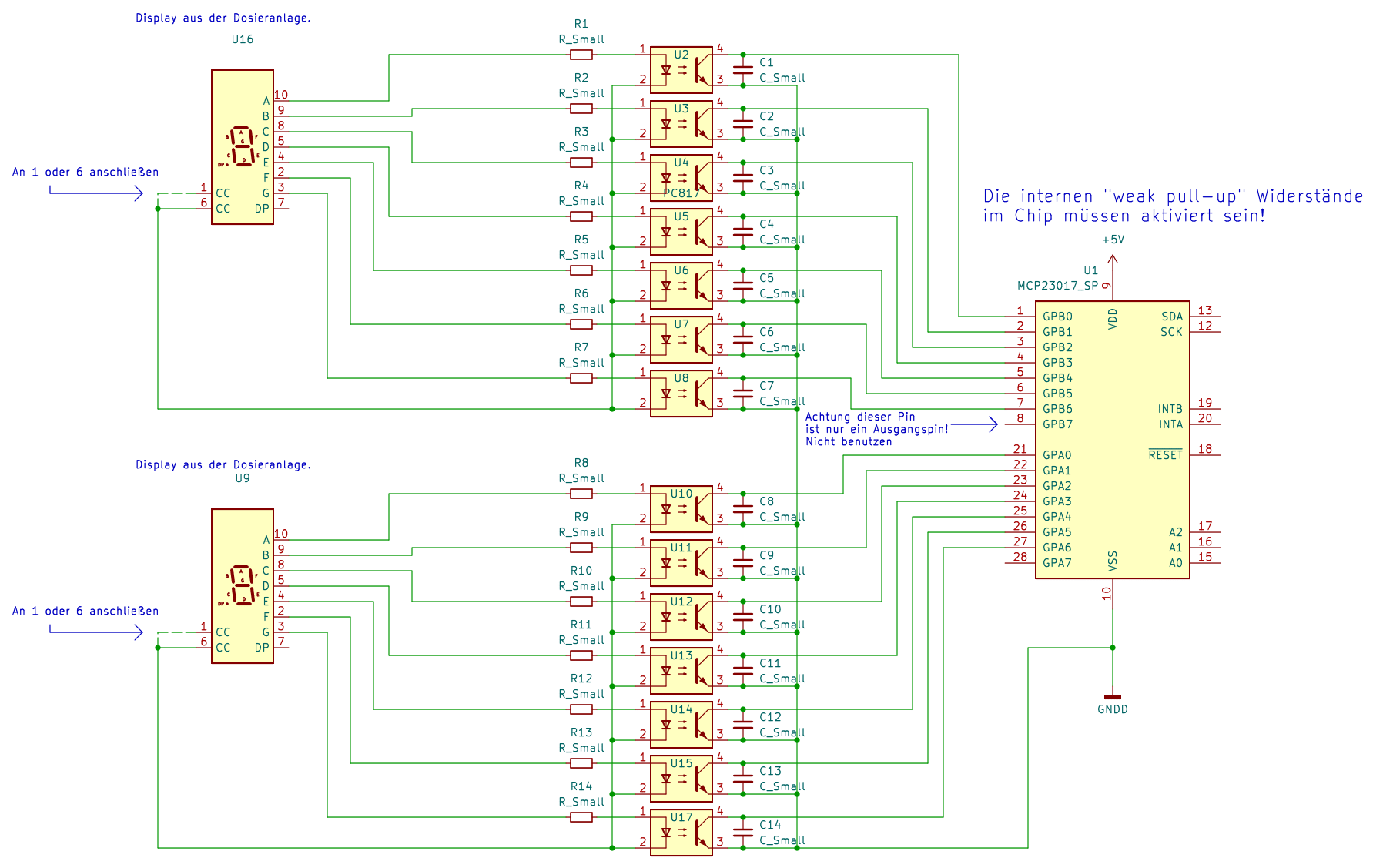
Schaltplan mit MCP23017 und 7-Segment-Anzeigen
aus der Dosieranlage. U9 Die internen "weak pull-up" Widerstände im Chip müssen aktiviert sein! MCP23017_SP GPB0 bis GPB7, GPA0 bis GPA7, SDA, SCK, VDD, VSS, RESET, INTB, INT A, A0, A1, A2
in „7 Segment Anzeige auslesen / MCP23017“ · Mikrocontroller und Digitale Elektronik · · Schaltpläne
-
PDF
RL-Extender.pdf
Draufsicht der Logik-Relaiseinheit 8*Anschluss Wandschalter und Relais Relaisplatine 12V f. Relais MCP23017 Rohrmotor- Anschluß 230V Eingang Anschluss 12V Steckernetzteil 433MHz Empfänger mit Antenne Logikplatine Rollladen-Extender Beschreibung Copyright (c) BBC-Hörer 2016-2018 - 6 - Abbildung 3: Aufbau
-
Datei
I2C_MCP23017.c
#include <avr/io.h> #include <avr/MCP23017.h> //I2C Initialisieren void I2C_Init(void); //I2C Start Signal senden void I2C_Start(void); //I2C Stop Signal senden void I2C_Stop(void); //I2C Daten übertragen void I2C_Senden(uint8_t Daten); //
in „I2C - Pull Up Widerstände“ · Mikrocontroller und Digitale Elektronik ·
-
PDF
Schaltplan_ATMega32_und_MCP23017.pdf
Schaltplan_ATMega32_und_MCP23017.pdf
in „ATMega32 liest über I2C-Bus die Eingänge vom MCP23017“ · Mikrocontroller und Digitale Elektronik ·
-
Datei
SunTracking_Heliostat_Program_V098.ino
minusOneButton, INPUT); altManualSpeedSwap = altManualSpeed; azManualSpeedSwap = azManualSpeed; //MCP23017 SETUP CODE FROM http://tronixstuff.wordpress.com/tutorials > chapter 41 // setup addressing style Wire.beginTransmission(0x20); Wire.write((byte)0x12); Wire.write((byte)0x20); // use table 1.4 addressing
in „Heliostatensteuerung mit Arduino Uno“ · Mikrocontroller und Digitale Elektronik ·