-
PDF
Fairchild_MOC306x.pdf
6-PIN DIP ZERO-CROSS PHOTOTRIAC DRIVER OPTOCOUPLER (600V PEAK) MOC3061-M MOC3062-M MOC3063-M MOC3162-M MOC3163-M PACKAGE SCHEMATIC ANODE 1 6MAIN TERM. 6 6 CATHODE 2 5NC* 1 N/C3 CROSSING 4 MAIN TERM. 1 CIRCUIT *DO NOT CONNECT (TRIAC SUBSTRATE) 6 1 DESCRIPTION The MOC306X-M
in „Triac Schaltung mit möglichst kleinem Haltestrom“ · Analoge Elektronik und Schaltungstechnik ·
-
PDF
MOC3061M.pdf
M O Ordering Information C 0 Order Entry Identifier X Option (Example) Description M , No option MOC3061M Standard Through Hole Device M S MOC3061SM Surface Mount Lead Bend O 3 SR2 MOC3061SR2M Surface Mount;Tape and Reel 1 T MOC3061TM 0.4" Lead Spacing X M V MOC3061VM VDE 0884 — TV MOC3061TVM VDE 0884, 0.4" Lead Spacing SV MOC3061SVM VDE 0884, Surface Mount - i SR2V MOC3061SR2VM VDE 0884, Surface Mount, Tape and Reel n I P e Marking Information o C r s 1 s P o MOC3061 2 o r V X YY Q 6 a c r v 3 4 5 r O Definitions p o 1 Fairchild
in „Mehrere Lasten an Wechselspannung schalten (Mosfet)“ · Analoge Elektronik und Schaltungstechnik ·
-
Bild
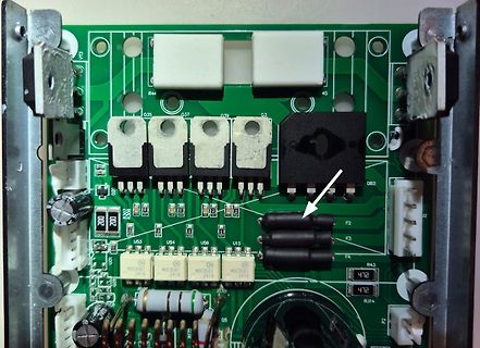
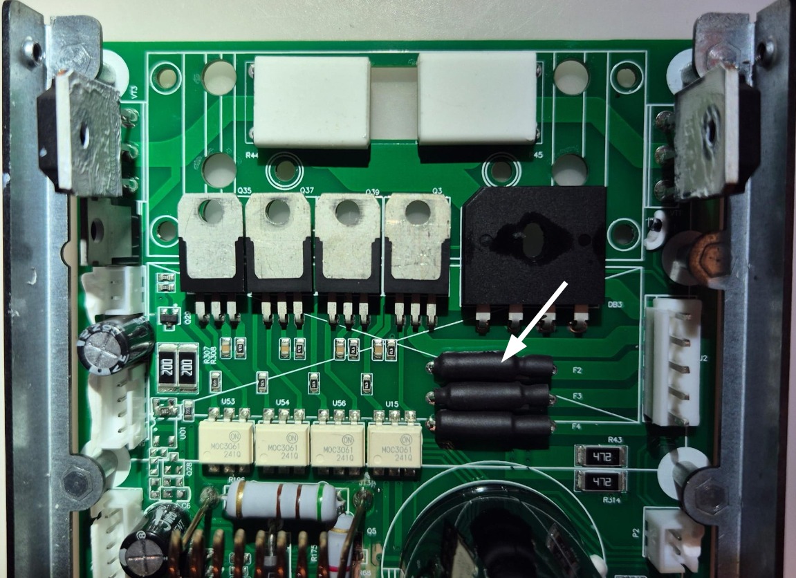
Nahaufnahme einer bestückten Leiterplatte mit Leistungshalbleitern
R44, Q35, Q37, Q39, Q3, DB3, Q28, R308, U53, U54, U56, U15, F2, F3, F4, MOC3061, MOC3061, MOC3061, 2410, R43, 472, 472, R314, F2, R175, Q5, Q6
in „KORAD KKG305P 30V 5A Netzteil defekt: Reparatur“ · Analoge Elektronik und Schaltungstechnik · · Platinenfotos
-
PDF
AN-3004.pdf
current necessary to latch the triac driver and ranges from 5 mA for the MOC3063 to 15 mA for the MOC3061. The Figure 4 shows a static dV/dt test circuit which can be used to test triac drivers and power triacs. The proposed test LED's forward voltage drop at IF= 30 mA is 1.5 V maxi- method is per EIA
in „MOC3063 vs MOC3063M“ · Analoge Elektronik und Schaltungstechnik ·
-
Bild
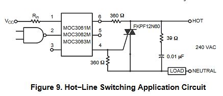
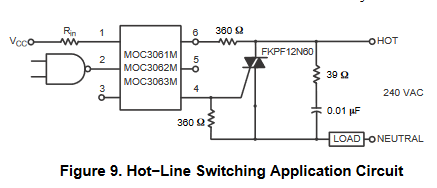
Schaltplan einer Hot-Line Switching Anwendung
VCC Rin 1 MOC3061M 6 360 Ω HOT 2 5 FKPF12N60 3 MOC3062M 4 39 Ω 240 VAC MOC3063M 360 Ω 0.01 µF LOAD NEUTRAL Figure 9. Hot-Line Switching Application Circuit
in „TRIAC Gate Widerstand raucht“ · Analoge Elektronik und Schaltungstechnik · · Schaltpläne
-
Bild
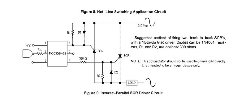
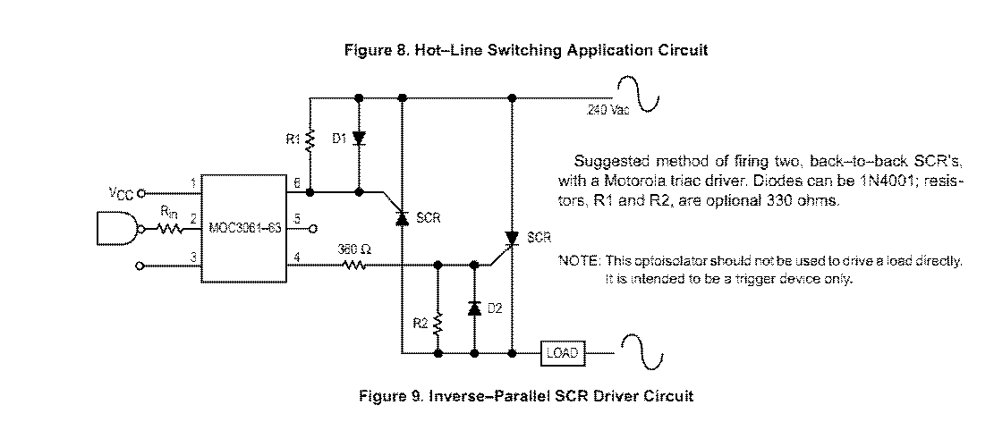
Schaltplan einer SCR-Treiberbeschaltung
Figure 8. Hot-Line Switching Application Circuit VCC RIN MOC3061-63 R1 D1 SCR 240 Vac SCR NOTE: This optoisolator should not be used to drive a load directly. It is intended to be a trigger device only. R2 D2 LOAD Figure 9. Inverse-Parallel SCR Driver Circuit
in „Warum schaltet mein Thyristor nicht durch?“ · Analoge Elektronik und Schaltungstechnik · · Schaltpläne
-
Bild
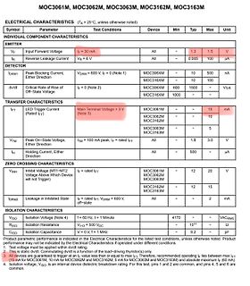
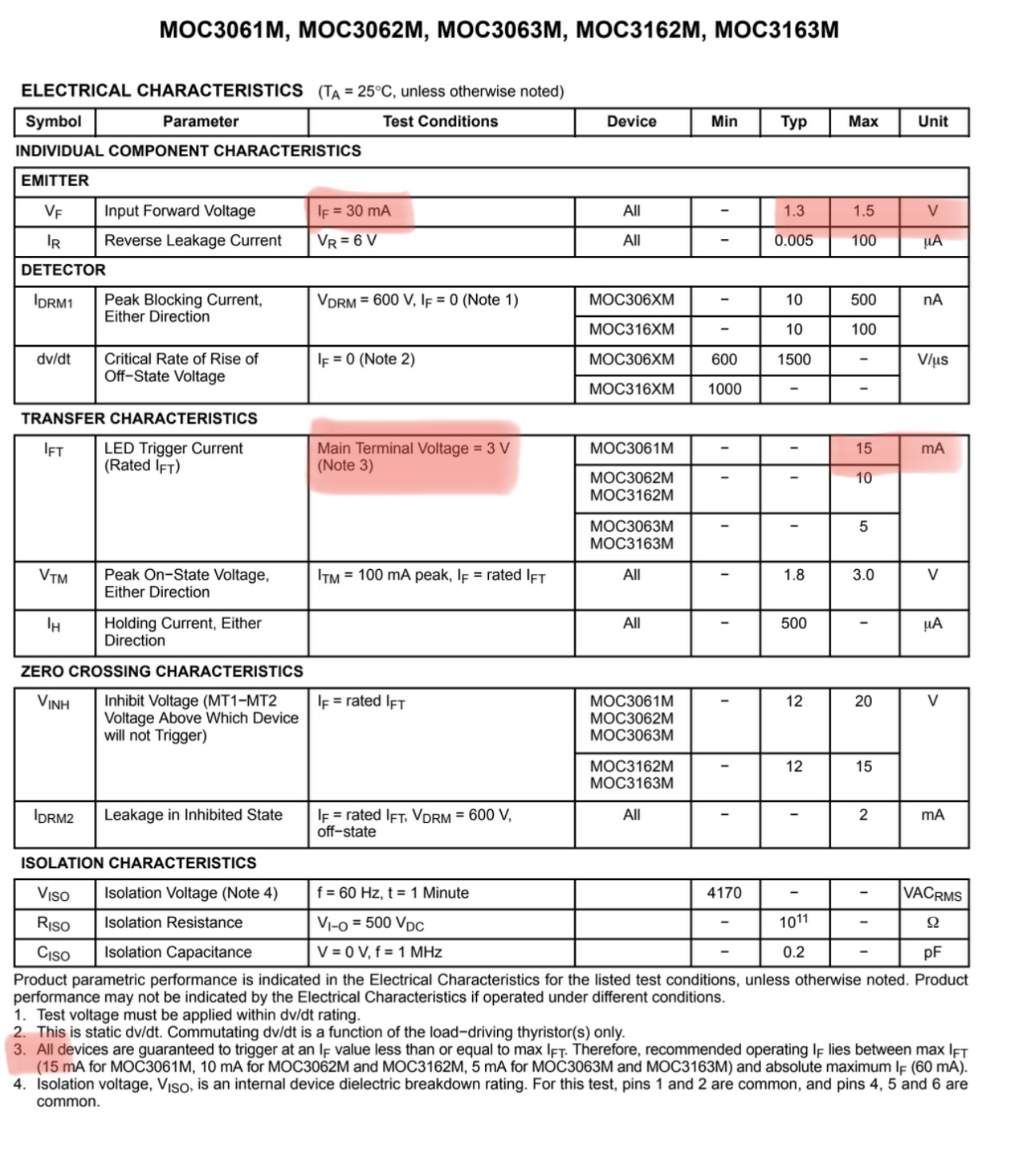
Tabelle der elektrischen Kennwerte für MOC3061 bis MOC3163M
MOC3061M, MOC3062M, MOC3063M, MOC3162M, MOC3163M ELECTRICAL CHARACTERISTICS EMITTER IF = 30 mA IR VR = 6 V DETECTOR IDRM1\{VDRM = 600 V, IF = 0\} DV/DT IH TRANSFER CHARACTERISTICS IFT VTM ZERO CROSSING CHARACTERISTICS
in „Suche Halbleiterelement als Ersatz für Relai in Radar-Bewegungsmelder“ · Analoge Elektronik und Schaltungstechnik · · Screenshots
-
PDF
AND8008-D.pdf
important to mention that the optocoupler devices Diagram 2 shows an electronic over–load circuit which (MOC3061)will supply the signal currents to the triacs and provides very reliable protection to the motor against over hence the motor keeping the same phase shifting (120 load conditions. The control signals
in „Halbleiterrelais (Solid State Relay) für Drehstrom bei 500W Last“ · Mikrocontroller und Digitale Elektronik ·
-
PDF
Motorola_tech_info.pdf
2000 MOC3041 400 15 20 125/280 2000 MOC3042 400 10 20 125/280 2000 MOC3043 400 5 20 125/280 2000 MOC3061 600 15 20 125/280 1500 MOC3062 600 10 20 125/280 1500 MOC3063 600 5 20 125/280 1500 MOC3162 600 10 15 125/280 1000 MOC3163 600 5 15 125/280 1000 MOC3081 800 15 20 125/280/320 1500 MOC3082 800 10 20
in „Isolationsspannung zwischen Doppel-FETs in einem SO8-Gehäuse“ · Analoge Elektronik und Schaltungstechnik ·
-
PDF
schema-electrique-1395717-renkforce-rf2000-imprimante-3d-appareil-pret-a-lemploi-banc-dimpression-chauffant.pdf
360R 1206 V4 REL1 MRA4003T3 P230 VSS H5 LED 0805 RM84-2012-35-5230 4 R105 1 X8 2 SSR1 3.3k 1 R90 MOC3061SVM VM1 1 1 220R VSS Q49 2 1 BC847 7 R103 5 6 7 8 C 1k B Ausgänge R38 51R B X19 4 1 HZ2 Q4 VM1 1 1 VSS VSS R39 680R 1 2 3 CSD18531Q5A 296-30573-1-ND 2 4 # HZ3 5 6 7 8 C GND R51 51R OUT1 4 VSS H6 LED
in „Spannungseinbruch nach Spule“ · Analoge Elektronik und Schaltungstechnik ·
-
PDF
HBD855-D_Thyristor_Theory.pdf
important to mention that the optocoupler devices Diagram 2 shows an electronic over−load circuit which (MOC3061) will supply the signal currents to the triacs and provides very reliable protection to the motor against over hence the motor keeping the same phase shifting (120 load conditions. The control signals for the two electronic electrical degrees) between lines. This is because these optocuplers (MOC3061) have zero crossing circuits within over−load circuits are received from the shunt resistors connected in parallel to the two current transformers placed them. in two of the three main lines (L1,

in „Ansteuerschaltung Thyristor und Triac“ · Analoge Elektronik und Schaltungstechnik ·
-
PDF
kicad_8450_dcm_liste_neu_v3.pdf
Opto-Triac, Vdrm 600V, Ift 15mA, DIP6 MOC3052M Random Phase Opto-Triac, Vdrm 600V, Ift 10mA, DIP6 MOC3061M Zero Cross Opto-Triac, Vdrm 600V, Ift 15mA, DIP6 MOC3062M Zero Cross Opto-Triac, Vdrm 600V, Ift 10mA, DIP6 MOC3063M Zero Cross Opto-Triac, Vdrm 600V, Ift 5mA, DIP6 MOC3081M Zero Cross Opto-Triac,
in „KiCAD Eeschema, Bibliotheksdokumentation *.dcm als PDF-Datei“ · Platinen ·