-
Datei
pcf8574.c
#include <stm32f10x.h> #include <stm32f10x_i2c.h> #include "pcf8574.h" #define PCF8574_I2Cx_RCC RCC_APB1Periph_I2C1 #define PCF8574_I2Cx I2C1 #define PCF8574_I2C_GPIO_RCC RCC_APB2Periph_GPIOB #define PCF8574_I2C_GPIO GPIOB #define PCF8574_I2C_PIN_SCL GPIO_Pin_6 #define PCF8574_I2C_PIN_SDA GPIO_Pin_7 #define PCF8574_I2C_ADDR 0x20 void pcf8574_write(uint8_t data) { pcf8574_i2c_start(); pcf8574_i2c_address_direction(PCF8574_I2C_ADDR << 1, I2C_Direction_Transmitter); pcf8574
in „STM32 I2C Probleme mit PCF8574“ · Mikrocontroller und Digitale Elektronik ·
-
Datei
PCF8574.cpp
// // FILE: PCF8574.cpp // AUTHOR: Rob Tillaart // DATE: 02-febr-2013 // VERSION: 0.3.0 // PURPOSE: Arduino library for PCF8574 - 8 channel I2C IO expander // URL: https://github.com/RobTillaart/PCF8574 // http://forum.arduino.cc
in „Fehler bei PCF8574.h Bibliotheke“ · Mikrocontroller und Digitale Elektronik ·
-
Datei
pcf8574_experiment.c
} /* Originalversion, die nichts einliest: unsigned char pcf8574_get_inputs (unsigned char address) { pcf8574_init (); pcf8574_send_start (); pcf8574_send_add_rw (address, 1); //Adresse senden und Lesen einstellen unsigned char input = pcf8574_read_byte (); pcf8574
in „(AVR-gcc) Lesen vom PCF8574 I2C-Port-Expander gelingt nicht“ · Mikrocontroller und Digitale Elektronik ·
-
PDF
PCF8574_PRAXIS_Beschaltung_ok_.pdf
1-0-1 Ports 57 - 64 BYTEPORT 8 PCF 8574 1-1-0 Ports 65 - 72 BYTEPORT 9 PCF 8574 1-1-1 Ports 73 - 80 BYTEPORT 10 PCF 8574A 0-0-0 Ports 81 - 88 BYTEPORT 11 PCF 8574A 0-0-1 Ports 89 - 96 BYTEPORT 12 PCF 8574A 0-1-0 Ports 97 - 104 BYTEPORT 13 PCF 8574A 0-1-1 Ports 105 - 112 BYTEPORT 14 PCF 8574A 1-0-0 Ports 113 - 120 BYTEPORT 15 PCF 8574A 1-0-1 Ports 121 - 128 BYTEPORT 16 PCF 8574A 1-1-0 Ports 129 - 136 BYTEPORT 17 PCF 8574A 1-1-1 Ports 137 - 144
in „pcf 8574 pMos highside driver“ · Mikrocontroller und Digitale Elektronik ·
-
Datei
lcdpcf8574.c
/* write instruction (RS=0, RW=0) */ dataport &= ~_BV(LCD_RS_PIN); dataport |= _BV(LCD_RW_PIN); pcf8574_setoutput(LCD_PCF8574_DEVICEID, dataport); pcf8574_setoutputpinhigh(LCD_PCF8574_DEVICEID, LCD_E_PIN); lcd_e_delay() ; data = pcf8574_getoutputpin(LCD_PCF8574_DEVICEID, LCD_DATA0_PIN) << 4; /* read high nibble first */ pcf8574_setoutputpinlow(LCD_PCF8574_DEVICEID, LCD_E_PIN); lcd_e_delay() ; /* Enable 500ns low */ pcf8574_setoutputpinhigh(LCD_PCF8574_DEVICEID, LCD_E_PIN); lcd_e_delay() ; data |= pcf8574_getoutputpin(LCD_PCF8574
in „Eclipse Kompilierung LCD Buchstabensalat“ · Mikrocontroller und Digitale Elektronik ·
-
PDF
PCF8574.pdf
Br) PCF8574DW ACTIVE SOIC DW 16 40 Green (RoHS NIPDAU Level-1-260C-UNLIM -40 to 85 PCF8574 & no Sb/Br) PCF8574DWR ACTIVE SOIC DW 16 2000 Green (RoHS NIPDAU Level-1-260C-UNLIM -40 to 85 PCF8574 & no Sb/Br) PCF8574DWRE4 ACTIVE SOIC DW 16 2000 Green (RoHS NIPDAU Level-1-260C-UNLIM -40 to 85 PCF8574 & no Sb/Br) PCF8574DWRG4 ACTIVE SOIC DW 16 2000 Green (RoHS NIPDAU Level-1-260C-UNLIM -40 to 85 PCF8574 & no Sb/Br) PCF8574N ACTIVE PDIP N 16 25 Green (RoHS NIPDAU N / A for Pkg Type -40 to 85 PCF8574N
-
Datei
pcf8574.c
char input = pcf8574_read_byte (); uart_puts("read byte - "); pcf8574_send_stop (); uart_puts("send stop\n"); return input; } void pcf8574_set_outputs (unsigned char address, unsigned char byte) { pcf8574_init (); pcf8574_send_start (); pcf8574_send_add_rw (address, 0); pcf8574_send_byte (byte); pcf8574_send_stop (); }
in „Problem mit PCF8574“ · Mikrocontroller und Digitale Elektronik ·
-
Datei
hardware.c
temp; temp=pcf8574_lesen(7); temp=temp&0xfb; pcf8574_schreiben(7,temp); } void led_gruen_aus() { volatile uchar temp; temp=pcf8574_lesen(7); temp=temp|4; pcf8574_schreiben(7,temp); } void relais_an() { volatile uchar temp; temp=pcf8574_lesen(1); temp=temp|1; pcf8574_schreiben(1,temp); } void relais_aus() { volatile uchar temp; temp=pcf8574_lesen(1); temp=temp&0xfe;; pcf8574_schreiben(1,temp); } uchar DectoHex(uchar value) { return
in „Philips PCF8583“ · Mikrocontroller und Digitale Elektronik ·
-
Datei
pcf8574.c
} unsigned char pcf8574_get_inputs (unsigned char address) { pcf8574_init (); pcf8574_send_start (); pcf8574_send_add_rw (address, 1); unsigned char input = pcf8574_read_byte (); pcf8574_send_stop (); return input; } void pcf8574_set_outputs (unsigned char address, unsigned char byte) { pcf8574_init (); pcf8574_send_start (); pcf8574_send_add_rw (address, 0); pcf8574_send_byte (byte); pcf8574_send_stop (); }
in „PCF8574AP mit ATMEGA8 - scheitere beim Zugriff“ · Mikrocontroller und Digitale Elektronik ·
-
Datei
pcf8574.c
} unsigned char pcf8574_get_inputs (unsigned char address) { pcf8574_init (); pcf8574_send_start (); pcf8574_send_add_rw (address, 1); unsigned char input = pcf8574_read_byte (); pcf8574_send_stop (); return input; } void pcf8574_set_outputs (unsigned char address, unsigned char byte) { pcf8574_init (); pcf8574_send_start (); pcf8574_send_add_rw (address, 0); pcf8574_send_byte (byte); pcf8574_send_stop (); }
in „PCF8574N Daten lesen“ · Mikrocontroller und Digitale Elektronik ·
-
Datei
pcf8574.c
********************************************************************************** unsigned char pcf8574_get_inputs (unsigned char address) { pcf8574_init (); pcf8574_send_start (); pcf8574_send_add_rw (address, 1); unsigned char input = pcf8574_read_byte (); pcf8574_send_stop (); return input; } void pcf8574_set_outputs (unsigned char address, unsigned char byte) { pcf8574_init (); pcf8574_send_start (); pcf8574_send_add_rw (address, 0); pcf8574_send_byte (byte); pcf8574_send_stop (); }
in „port-expander-matrix Bug ATmega8 hängt sich in der letzten Zeile auf“ · Mikrocontroller und Digitale Elektronik ·
-
PDF
PCF8574_4.pdf
I C-bus. This means that the PCF8574 can remain a simple slave device. 2 GENERAL DESCRIPTION The PCF8574 and PCF8574A versions differ only in their ThePCF8574isasiliconCMOScircuit.Itprovidesgeneral slave address as shown in Fig.10. purpose
in „PCF8574 Routine in C“ · Mikrocontroller und Digitale Elektronik ·
-
PDF
PCF8574_4.pdf
I C-bus. This means that the PCF8574 can remain a simple slave device. 2 GENERAL DESCRIPTION The PCF8574 and PCF8574A versions differ only in their ThePCF8574isasiliconCMOScircuit.Itprovidesgeneral slave address as shown in Fig.10. purpose
in „I²C tolle Alternative“ · Mikrocontroller und Digitale Elektronik ·
-
PDF
PCF8574_4.pdf
I C-bus. This means that the PCF8574 can remain a simple slave device. 2 GENERAL DESCRIPTION The PCF8574 and PCF8574A versions differ only in their ThePCF8574isasiliconCMOScircuit.Itprovidesgeneral slave address as shown in Fig.10. purpose
in „I2C mit Display parallel?“ · Mikrocontroller und Digitale Elektronik ·
-
PDF
Data_PCF_8574.pdf
slave address as shown in Fig.9. 3 ORDERING INFORMATION PACKAGE TYPE NUMBER NAME DESCRIPTION VERSION PCF8574P; DIP16 plastic dual in-line package; 16 leads (300 mil) SOT38-1 PCF8574AP PCF8574T; SO16 plastic small outline package; 16 leads; body width 7.5 mm SOT162-1 PCF8574AT PCF8574TS SSOP20 plastic shrink
in „Austausch IC mit DIP gegen SMD“ · Mikrocontroller und Digitale Elektronik ·
-
PDF
PCF8574.pdf
slave address as shown in Fig.9. 3 ORDERING INFORMATION PACKAGE TYPE NUMBER NAME DESCRIPTION VERSION PCF8574P; DIP16 plastic dual in-line package; 16 leads (300 mil) SOT38-1 PCF8574AP PCF8574T; SO16 plastic small outline package; 16 leads; body width 7.5 mm SOT162-1 PCF8574AT PCF8574TS SSOP20 plastic shrink
in „[V] #VERKAUFT# Platine mit 8 Stück DLG7137, 5*7 Punktmatrix“ · Markt ·
-
Datei
PCF8574.h
/index.php?topic=184800 // // HISTORY: // see PCF8574.cpp file // #include "Arduino.h" #include "Wire.h" #define PCF8574_LIB_VERSION (F("0.3.0")) #ifndef PCF8574_INITIAL_VALUE #define PCF8574_INITIAL_VALUE 0xFF #endif #define PCF8574_OK 0x00 #define PCF8574_PIN_ERROR 0x81 #define PCF8574_I2C_ERROR 0x82 class PCF8574 { public: explicit PCF8574(const uint8_t deviceAddress, TwoWire *wire = &Wire); #if defined (ESP8266) || defined(ESP32) bool begin(uint8
in „Fehler bei PCF8574.h Bibliotheke“ · Mikrocontroller und Digitale Elektronik ·
-
Datei
PCF8574_0.H
PCF8574A_Adr_WR (char)0x70 // schreiben #define PCF_RD_ADRESSE 1 // PCF_Adr immer gerade => RD_ADRESSE =+1 #define PCF8574_WR0 PCF8574A_Adr_WR // schreiben A= 0x70 , sonst 0x40 #define PCF8574_WR1 ( PCF8574_WR0 +2 ) // schreiben, lesen = +1 #define PCF8574_WR2 ( PCF8574_WR0 +4 ) // -------------------------------------------------- void WR_PCF8574(char Wohin , char was) ; char RD_PCF8574(char Woher) ; // ---------------------------------------------
in „MSP430 pcf8574“ · Mikrocontroller und Digitale Elektronik ·
-
Datei
PCF8574.c
#include <avr/pcf8574.h> void pcf8574_init (void) { /*einstellen des bus-taktes*/ TWBR = 0x10; } unsigned char pcf8574_send_start (void) { /*schreiben der start bedingung 10100100 in das TWCR */ TWCR = 0xA4; /*warten bis
in „PCF8574 an Atmega 168p“ · Mikrocontroller und Digitale Elektronik ·
-
Datei
i2c_test.c
_Read(PCF8574_I2C_ADR, &Tasten_A); // Lesezugriff P11 PCA9536_Read(PCA9536_I2C_ADR, &Tasten_B); // Lesezugriff Abfrage WTMA if(~Tasten_B & 0x08) { // Taste 4 kopieren pcf8574_buffer &= ~0x08; } else { pcf8574_buffer |= 0x08; } if (~Taste_A & 0x08) { // Taste 1 kopieren pcf8574_buffer &= ~0x01; } else { pcf8574_buffer |= 0x01; } PCF8574_Write(PCF8574_I2C_ADR, pcf8574_buffer); PCA9536_Write(PCA9536_I2C_ADR, PCA9536_OUTPUT_REG, Taste_A & 0x03); } }
in „Denkfehler mit PCA9536 (Problem)“ · Mikrocontroller und Digitale Elektronik ·
-
Datei
i2c_test.c
(PCF8574_I2C_ADR)) { PORTC |= (1<<PC5); // error while(1); // stop } // PCA9536 P0-P2 auf OUTPUT umstellen, P3 Input PCA9536_Write(PCA9536_I2C_ADR, PCA9536_CONFIG_REG, 0x08); while(1) { // Hauptschleife PCF8574
in „Denkfehler mit PCA9536 (Problem)“ · Mikrocontroller und Digitale Elektronik ·
-
PDF
I2C-Bus_Adressliste__Elektronik-Magazin.pdf
I2C-Bus Adressliste: Elektronik-Magazin http://www.elektronik-magazin.de/page/i2c-bus-adressliste-23 PCF8574 PCF8574 PCF8574 PCF8574 PCF8574 PCF8574 PCF8574 PCF8574 20.12.2010 TDA8444 TDA8444 TDA8444 TDA8444 TDA8444 TDA8444 TDA8444 TDA8444 heidi 0101 User (0) 0110 0111 PCF8576 PCF8576 PCF8577 PCF8577A PCF8578 PCF8566 PCF8566 11.10.2010 SAA1064 SAA1064 SAA1064 SAA1064 PCF8579 PCF8574A PCF8574A PCF8574A PCF8574A PCF8574A PCF8574A PCF8574A peterjo 1000 TEA6320 TDA8424 TDA8425 User (0) TEA6330 TDA8425 TDA8415 TDA8426 TDA8416 TDA8420 TDA8420 TDA8440 TDA8421 TDA8421 TDA8940 31.08.2010
in „PCF8574/PCF8574A Adressierung“ · Mikrocontroller und Digitale Elektronik ·
-
Datei
DG14032_PCF8574_lesen_1.c
= 0x40 oder ein Bit nach rechts verschoben: 0x20 // pcf8574_set_outputs (0x20, i); //PCF8574 hat Adresse 0x20!!! <<<---<<<--- OK funktioniert 0x20 ist falsch, da UP 0..8 erwartet.!!!!!!!!!!!!!<<<---<<<--- // pcf8574_set_outputs (0, i); //PCF8574 hat Adresse
in „(AVR-gcc) Lesen vom PCF8574 I2C-Port-Expander gelingt nicht“ · Mikrocontroller und Digitale Elektronik ·
-
Datei
I2C_PCF8574.c
include "xc.h" #include "stdio.h" #include "stdarg.h" #include "stdlib.h" #include "I2C.h" #define PCF8574_ADDR_WRITE 0x70 #define PCF8574_ADDR_READ 0x71 //liest den PCF8574 aus (Status der Eingänge) char PCF8574read() { char temp; i2c_start(); send_i2c_byte(PCF8574_ADDR_READ); __delay_us(10); temp = i2c_read(); reset_i2c_bus(); return temp; } //setzt Ausgänge am PCF8574 void PCF8574write(char data) { i2c_start(); send_i2c_byte(PCF8574_ADDR_WRITE); send_i2c_byte(data); reset_i2c_bus(); }
in „I2C PIC 18F2550 und MCP4728“ · Mikrocontroller und Digitale Elektronik ·
-
Datei
Sklave_LCD_Init.asm
HD44780 ; LCD 1602 / 2004 ; ---- ; | | ; VCC -- | 1 | VSS ; GND -- | 2 | VDD ; R <-------- | 3 | VEE ; PCF8574 P0 --> | 4 | RS ; PCF8574 P1 --> | 5 | R/W ; PCF8574 P2 --> | 6 | E ; x | 7 | D0 ; x | 8 | D1 ; x | 9 | D2 ; x | 10 | D3 ; PCF8574 P4 --> | 11 | D4 ; PCF8574 P5 --> | 12 | D5 ; PCF8574 P6 --> | 13 | D6 ; PCF8574 P7 --> | 14 | D7 ; PCF8574 P3 --> | 15 | A ; GND -- | 16 | C ; | | ; ---- ; ; ------------------------------------------------------------------------- ; externes DISPLAY .equ DP_RS = 0 .equ DP_RW
in „AVR ATtiny13 DS18B20/DS18S20 I2C PCF8574 LCD Temperaturanzeige“ · Projekte & Code ·
-
Datei
Arduino_lib.txt
\file LiquidCrystal_PCF8574.h /// \brief LiquidCrystal library with PCF8574 I2C adapter. /// /// \author Matthias Hertel, http://www.mathertel.de /// /// \copyright Copyright (c) 2019 by Matthias Hertel.\n /// /// The library
in „PCF8574 I2c Adapter mit ASM ansteuern“ · Mikrocontroller und Digitale Elektronik ·
-
Datei
i2clcd.h
LCD_E_PIN 2 /**< LCD-Pin E is connected to P2 on the PCF8574 */ #define LCD_LED_PIN 3 /**< LCD-PIN LED+ is connected to P3 on the PCF8574 */ #define LCD_D4_PIN 4 /**< LCD-Pin D4 is connected to P4 on the PCF8574 */ #define LCD_D5_PIN 5 /**< LCD-Pin D5 is connected to P5 on the PCF8574 */ #define LCD_D6_PIN 6 /**< LCD-Pin D6 is connected to P6 on the PCF8574 */ #define LCD_D7_PIN 7 /**< LCD-Pin D7 is connected to P7 on the PCF8574 */ /* dez Eingabe der Port-Nummern */ /*@}*/ //-
in „4x20-LCD läuft nicht richtig“ · Mikrocontroller und Digitale Elektronik ·
-
Datei
i2c-hd44780.c
|= LCD_D7; set_pcf8574(out | rs | LCD_E); _delay_ms(3); set_pcf8574(out | rs ); } void lcd_clear() { lcd_cmd(0x01); // clear display lcd_home(); } void lcd_home() { lcd_cmd(0x80); cursor_x = 0; cursor_y = 0; } void lcd_setcursor
in „STM32F407, I2C LCD, Initialisierung“ · Mikrocontroller und Digitale Elektronik ·
-
Datei
i2clcd.h
defgroup PIN_ASSIGNMENT PIN ASSIGNMENT This pin assignment shows how the display is connected to the PCF8574. */ /*@{*/ #define LCD_RS_PIN 0 /**< LCD-Pin RS is connected to P0 on the PCF8574 */ #define LCD_RW_PIN 1 /**< LCD-Pin RW is connected to P1 on the PCF8574 */ #define LCD_E_PIN 2 /**< LCD-Pin D4 is
in „4x20-LCD läuft nicht richtig“ · Mikrocontroller und Digitale Elektronik ·
-
Datei
main.cpp
#include <Arduino.h> #include <pcf8574_esp.h> #include <PolledTimeout.h> #define PCF_INT_PIN D5 #define PCF_DEBOUNCE_MS 50 #define PCF_INPUT1 3 #define PCF_INPUT2 2 #define PCF_INPUT3 1 #define PCF_INPUT4 0 PCF857x pcf8574(0x20, &Wire)
in „ESP8266 mit PCF8574 und Taster - Interrupt vom PCF "spinnt"?“ · Mikrocontroller und Digitale Elektronik ·
-
Datei
i2clcd.h
*/ #define LCD_D5_PIN 5 /**< LCD-Pin D5 is connected to P5 on the PCF8574 */ #define LCD_D6_PIN 6 /**< LCD-Pin D6 is connected to P6 on the PCF8574 */ #define LCD_D7_PIN 7 /**< LCD-Pin D7 is connected to P7 on the PCF8574 */ #define LCD_RS_PIN 0 /**< LCD-Pin RS is connected to P0 on the PCF8574 */ #define LCD_RW_PIN 1 /**< LCD-Pin RW is connected to P1 on the PCF8574 */ #define LCD_E_PIN 2 /**< LCD-Pin E is connected to P2 on the PCF8574 */ #define LCD_LIGHT_PIN 3 /**< LCD backlight is connected
in „Probleme mit meinem LCD-Display“ · Mikrocontroller und Digitale Elektronik ·
-
Datei
hd44780_i2c.h
|= 1 << lcd_clk; pcf8574_write(pcf_value); } #define clk_clr() { pcf_value &= ~(1 << lcd_clk); pcf8574_write(pcf_value); } #define rs_set() { pcf_value |= 1 << lcd_rs; pcf8574_write(pcf_value); } #define rs_clr() { pcf_value &= ~(1 << lcd_rs); pcf8574_write(pcf_value); } extern char wherex, wherey; // beinhaltet die aktuelle Position des Cursors /* ################################################################# Prototypen ####################
in „(sehr) kleines "FrameWork" für ATtiny44“ · Projekte & Code ·
-
Datei
LCD_162_TWI.c
| 0b00001000; // `E`-Bit auf `1` setzen pcf8574ap_writebyte(LCD_ADRESSE, lcd_port); _delay_us (1); // Verzögerung von mindestens 220Mycros lcd_port = lcd_port & ~0b00001000; // `E`-Bit auf `0` setzen pcf8574ap_writebyte(LCD_ADRESSE, lcd_port);
in „Problem LCD über PCF8574AP ansteuern“ · Mikrocontroller und Digitale Elektronik ·
-
PDF
PCF8574AN.pdf
ORDERING INFORMATION † ORDERABLE TOP-SIDE TA PACKAGE PART NUMBER MARKING QFN − RGY Tape and reelPCF8574ARGYR PF574A PDIP − N Tube PCF8574AN PCF8574AN Tube PCF8574ADW −40°C to 85°CSOIC − DW PCF8574A Tape and reelPCF8574ADWR TSSOP − PW Tape and reelPCF8574APWR PF574A TVSOP − DGV Tape and reelPCF8574ADGVR
in „Adresse PCF8574“ · Mikrocontroller und Digitale Elektronik ·
-
Datei
I2C_PCF8574.h
File: I2C.h * Author: Standarduser * * Created on 1. April 2014, 20:00 */ /*Interface header for PCF8574*/ #ifndef I2C_PCF8574_H #define I2C_PCF8574_H char PCF8574read(); //read PCF8574 void PCF8574write(char data); //write data to PCF8574 #endif /* I2C_H */
in „I2C PIC 18F2550 und MCP4728“ · Mikrocontroller und Digitale Elektronik ·
-
Datei
i2clcd.h
*/ #define LCD_D5_PIN 5 /**< LCD-Pin D5 is connected to P5 on the PCF8574 */ #define LCD_D6_PIN 6 /**< LCD-Pin D6 is connected to P6 on the PCF8574 */ #define LCD_D7_PIN 7 /**< LCD-Pin D7 is connected to P7 on the PCF8574 */ #define LCD_RS_PIN 0 /**< LCD-Pin RS is connected to P0 on the PCF8574 */ #define LCD_RW_PIN 1 /**< LCD-Pin RW is connected to P1 on the PCF8574 */ #define LCD_E_PIN 2 /**< LCD-Pin E is connected to P2 on the PCF8574 */ #define LCD_LIGHT_PIN 3 /**< LCD backlight is connected
in „Tastenentprellung seltsames Phänomen“ · Mikrocontroller und Digitale Elektronik ·
-
Datei
twi_lib.c
Macro for delay of ms and us #endif const char strP_DS1631[] PROGMEM = "DS1631"; const char strP_PCF8574[] PROGMEM = "PCF8574"; const char strP_PCF8574A[] PROGMEM = "PCF8574A"; const char strP_PCF8583[] PROGMEM = "PCF8583"; const char strP_TWI_Dev[] PROGMEM = "TWI_Dev"; // Not named TWI Device const char strP_Err_DS1631[] PROGMEM = "Err_DS1631"; const char strP_Err_PCF8574[] PROGMEM = "Err_PCF8574"; const char strP_Err_PCF8574A[] PROGMEM = "Err_PCF8574A"; const char strP_Err_PCF8583[] PROGMEM = "Err_PCF8583"; const char strP_Err_TWI_Dev[] PROGMEM = "Err_TWI_Dev"; //
in „TWI MUX per SW an einem Port“ · Mikrocontroller und Digitale Elektronik ·
-
Datei
i2clcd.h
defgroup PIN_ASSIGNMENT PIN ASSIGNMENT This pin assignment shows how the display is connected to the PCF8574. */ /*@{*/ #define LCD_D4_PIN 4 /**< LCD-Pin D4 is connected to P4 on the PCF8574 */ #define LCD_D5_PIN 5 /**< LCD-Pin D5 is connected to P5 on the PCF8574 */ #define LCD_D6_PIN 6 /**< LCD-Pin D6 is connected to P6 on the PCF8574 */ #define LCD_D7_PIN 7 /**< LCD-Pin D7 is connected to P7 on the PCF8574 */ #define LCD_RS_PIN 0 /**< LCD-Pin RS is connected to P0 on the PCF8574 */ #define LCD_RW_PIN 1 /**< LCD-Pin RW is connected
in „TC1602E-01 von Pollin über I2C“ · Mikrocontroller und Digitale Elektronik ·
-
Datei
i2clcd.h
defgroup PIN_ASSIGNMENT PIN ASSIGNMENT This pin assignment shows how the display is connected to the PCF8574. */ /*@{*/ #define LCD_D4_PIN 0 /**< LCD-Pin D4 is connected to P0 on the PCF8574 */ #define LCD_D5_PIN 1 /**< LCD-Pin D5 is connected to P1 on the PCF8574 */ #define LCD_D6_PIN 2 /**< LCD-Pin D6 is connected to P2 on the PCF8574 */ #define LCD_D7_PIN 3 /**< LCD-Pin D7 is connected to P3 on the PCF8574 */ #define LCD_RS_PIN 4 /**< LCD-Pin RS is connected to P4 on the PCF8574 */ #define LCD_RW_PIN 5 /**< LCD-Pin RW is connected
in „Zeilenadressen LCD 4x20 blau“ · Mikrocontroller und Digitale Elektronik ·
-
Datei
i2clcd.h
defgroup PIN_ASSIGNMENT PIN ASSIGNMENT This pin assignment shows how the display is connected to the PCF8574. */ /*@{*/ #define LCD_D4_PIN 0 /**< LCD-Pin D4 is connected to P0 on the PCF8574 */ #define LCD_D5_PIN 1 /**< LCD-Pin D5 is connected to P1 on the PCF8574 */ #define LCD_D6_PIN 2 /**< LCD-Pin D6 is connected to P2 on the PCF8574 */ #define LCD_D7_PIN 3 /**< LCD-Pin D7 is connected to P3 on the PCF8574 */ #define LCD_RS_PIN 4 /**< LCD-Pin RS is connected to P4 on the PCF8574 */ #define LCD_RW_PIN 5 /**< LCD-Pin RW is connected
in „I2C, Mega32, Pollin-LCD“ · Mikrocontroller und Digitale Elektronik ·
-
Datei
i2clcd.h
defgroup PIN_ASSIGNMENT PIN ASSIGNMENT This pin assignment shows how the display is connected to the PCF8574. */ /*@{*/ #define LCD_D4_PIN 0 /**< LCD-Pin D4 is connected to P0 on the PCF8574 */ #define LCD_D5_PIN 1 /**< LCD-Pin D5 is connected to P1 on the PCF8574 */ #define LCD_D6_PIN 2 /**< LCD-Pin D6 is connected to P2 on the PCF8574 */ #define LCD_D7_PIN 3 /**< LCD-Pin D7 is connected to P3 on the PCF8574 */ #define LCD_RS_PIN 4 /**< LCD-Pin RS is connected to P4 on the PCF8574 */ #define LCD_RW_PIN 5 /**< LCD-Pin RW is connected
in „LCD am I2C Bus“ · Mikrocontroller und Digitale Elektronik ·
-
Datei
i2clcd.h
defgroup PIN_ASSIGNMENT PIN ASSIGNMENT This pin assignment shows how the display is connected to the PCF8574. */ /*@{*/ #define LCD_D4_PIN 0 /**< LCD-Pin D4 is connected to P0 on the PCF8574 */ #define LCD_D5_PIN 1 /**< LCD-Pin D5 is connected to P1 on the PCF8574 */ #define LCD_D6_PIN 2 /**< LCD-Pin D6 is connected to P2 on the PCF8574 */ #define LCD_D7_PIN 3 /**< LCD-Pin D7 is connected to P3 on the PCF8574 */ #define LCD_RS_PIN 4 /**< LCD-Pin RS is connected to P4 on the PCF8574 */ #define LCD_RW_PIN 5 /**< LCD-Pin RW is connected
in „LCD am I2C Bus“ · Mikrocontroller und Digitale Elektronik ·
-
Datei
I2C_Master.asm
--------- ; PCF8574 : START | 0 | 1 | 0 | 0 | 0 | A2 | A1 | A0 |R/w| ; ---------------------------------------- .set Adresse = 0B0100_0000 ; Address 40 PCF8574 Read ;.set Adresse = 0B0100_1110 ; Address 47 PCF8574 Read
in „AVR ATtiny13 DS18B20/DS18S20 I2C PCF8574 LCD Temperaturanzeige“ · Projekte & Code ·
-
PDF
Projekt_Heimautomation.pdf
Konflikt kommt. Widerständebenötigt.Diehabeichnichtvergessen. Den I2C-Bus benötige ich, um mit dem PCF8574 zu kommunizieren. - Die SPI-Schnittstelle befindet sich auf den Pins 19, 21, 23 und 24, wobei der Pin 24 der CS-Pin ist und PCF8574 – S0-Zähler DasCAN-InterfacebestehtimWesentlichenauszweiBau- teilen
in „Schaltplan für Haussteuerung im Hutschienengehäuse (Raspberry Pi, CAN, MCP2515, MCP2562, PCF8574)“ · Haus & Smart Home ·
-
 Bild
Bild
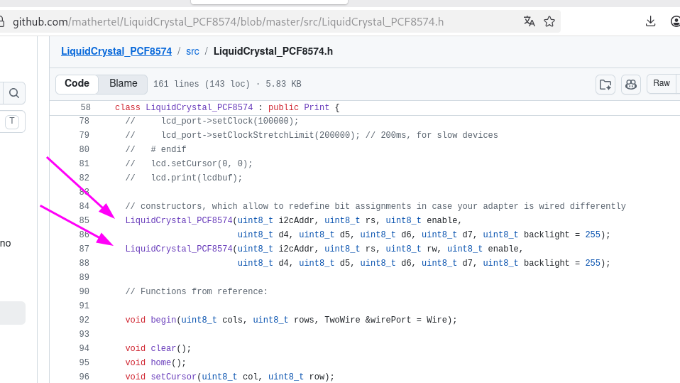
GitHub-Screenshot von C++ Quellcode
github.com/mathertel/LiquidCrystal_PCF8574/blob/master/src/LiquidCrystal_PCF8574.h LiquidCrystal_PCF8574 : public Print { // lcd_port->setClock(100000); // lcd_port->setClockStretchLimit(200000); // 200ms, for slow devices // endif lcd.setCursor
in „TWI1 auf Atmega328PB schlägt fehl“ · Mikrocontroller und Digitale Elektronik · · Screenshots
-
Datei
Compiling.txt
AppData\Local\Temp\arduino_build_389122\libraries\MyPCA8574\MyPCA8574.cpp.o Compiling library "MyPCF8574" Zuvor kompilierte Datei wird verwendet: C:\Users\Worker\AppData\Local\Temp\arduino_build_389122\libraries\MyPCF8574\MyPCF8574.cpp.o Compiling library "Modellbahn" Compiling library "MyPCF8575" Compiling
in „BFD DWARF Error - avr-gcc 13.2 & binutils 2.41“ · Mikrocontroller und Digitale Elektronik ·
-
Datei
lcd_io1.h
(again!). Use sbi() and cbi() commands instead. MODE 3 INFORMATION mode 3 uses the I2C bus and a PCF8574. Up to 8 different lcd units can be connected. You also need to make a very simple cirquit with PCF8574 (one for each lcd). Also the pins can be scattered all over the place (any LCD pin in any PCF8574
-
Datei
lcd_io1.h
(again!). Use sbi() and cbi() commands instead. MODE 3 INFORMATION mode 3 uses the I2C bus and a PCF8574. Up to 8 different lcd units can be connected. You also need to make a very simple cirquit with PCF8574 (one for each lcd). Also the pins can be scattered all over the place (any LCD pin in any PCF8574
in „LCD I2C Bibliothek“ · Mikrocontroller und Digitale Elektronik ·
-
Datei
main.cpp
#include <Arduino.h> #include <pcf8574_esp.h> #include <PolledTimeout.h> #define PCF_INT_PIN D5 #define PCF_DEBOUNCE_MS 50 #define PCF_INPUT1 3 #define PCF_INPUT2 2 #define PCF_INPUT3 1 #define PCF_INPUT4 0 PCF857x pcf8574(0x20, &Wire)
in „ESP8266 mit PCF8574 und Taster - Interrupt vom PCF "spinnt"?“ · Mikrocontroller und Digitale Elektronik ·
-
Datei
main.cpp
#include <Arduino.h> #include <pcf8574_esp.h> #include <PolledTimeout.h> #define PCF_INT_PIN D5 #define PCF_DEBOUNCE_MS 50 #define PCF_INPUT1 3 #define PCF_INPUT2 2 #define PCF_INPUT3 1 #define PCF_INPUT4 0 #define INPUT_CHECK_INTERVAL
in „ESP8266 mit PCF8574 und Taster - Interrupt vom PCF "spinnt"?“ · Mikrocontroller und Digitale Elektronik ·