-
Datei
hsv-test.c
array length makro function #ifndef arrlen #define arrlen(A) (sizeof(A) / sizeof(A[0])) #endif // WS2811 update volatile uint8_t ws2811_todo = 0; uint8_t *ws2811_ptr; void ws2811update( const RGB_t *rgb, uint8_t len ); //################ MAIN ################ int main( void ) { PORTB = 0xFF; // pullups
in „HSV -> RGB berechnet wirre Farben“ · Mikrocontroller und Digitale Elektronik ·
-
Datei
ws2811.c
#include "ws2811.h" #define nop() \ asm volatile ("nop") void ws2811_reset(void) { WSPORT &= ~(1<<WSPIN); for (int i=0; i<410; i++) { nop(); } } void wswrite_zero(void) { // 500ns +- 150ns high WSPORT |= (1<<WSPIN)
in „WS2811 Lib (optimierungen)“ · Mikrocontroller und Digitale Elektronik ·
-
PDF
ws2811.pdf
oncontroller 104 104 VCC e 33R VDD OUTB OUTG OUTR 33R 33R VDD OUTB OUTG OUTR D l DAT DIN DO DIN DO E t WS2811 WS2811 33R L o GND GND GND GND GND c Fig 1 This driving mode use constant current output, the advantage of is the LED can retain luminance and colour temperature when the power supply lessen. We require
in „Touch bauen, suche günstigere alternativen“ · Mikrocontroller und Digitale Elektronik ·
-
PDF
ws2811.pdf
oncontroller 104 104 VCC e 33R VDD OUTB OUTG OUTR 33R 33R VDD OUTB OUTG OUTR D l DAT DIN DO DIN DO E t WS2811 WS2811 33R L o GND GND GND GND GND c Fig 1 This driving mode use constant current output, the advantage of is the LED can retain luminance and colour temperature when the power supply lessen. We require
in „WS2811 zu hoher Ruhestrom?“ · Analoge Elektronik und Schaltungstechnik ·
-
Datei
main.c
nop(); nop(); nop(); *port = cleared_portbit; } mask >>= 1; } while (1) ; } #endif void leds_out_ws2811_asm(unsigned char *leds, int count, volatile uint8_t *port, unsigned char portbit); void leds_out_ws2811(unsigned char *leds, int count){ #ifdef PROTO leds_out_ws2811_proto(leds, count, &PORTB, 1 <
in „[Mitbestellung] SMD5050 RGB-LED mit integriertem 8-bit PWM Controller“ · Markt ·
-
Datei
ws2812.h
Alan Burlison, alan@bleaklow.com. All rights reserved. * Use is subject to license terms. */ /* * WS2811 RGB LED driver. */ #ifndef WS2811_h #define WS2811_h // RGB value structure. typedef struct __attribute__ ((__packed__)) { uint8_t r; uint8_t g; uint8_t b; } RGB_t; #ifndef ARRAYLEN #define ARRAYLEN
in „Portierung ASM“ · Mikrocontroller und Digitale Elektronik ·
-
Datei
ws2811.h
#define WSDDR DDRA #define WSPORT PORTA #define WSPIN PA1 #define ledanzahl 100 // 1 - 1024 void ws2811_reset(void); void ws2811_init(void); void wswrite_zero(void); void wswrite_one(void); void ws2811_rgbsetall(int r, int g, int b); void ws2811_rgbsetone(int led, int r, int g, int b); void ws2811_send
in „WS2811 Lib (optimierungen)“ · Mikrocontroller und Digitale Elektronik ·
-
Datei
ws2811.s
11 * * T1H 1µS 16 * T1L 0,25µS 4 * * doesn't work: * T1H 0,500µS 8 * T1L 0,725µS 12 * */ .file "ws2811.s" __SREG__ = 0x3f __SP_H__ = 0x3e __SP_L__ = 0x3d __CCP__ = 0x34 __tmp_reg__ = 0 __zero_reg__ = 1 .global __do_copy_data .global __do_clear_bss .text .global leds_out_ws2811_asm .type leds_out_ws2811_asm, @function leds_out_ws2811_asm: /* prologue: function */ /* frame size = 0 */ mov __tmp_reg__,r18 movw r30,r24 adiw r24,1 movw r18,r24 add r18,r22 adc r19,r23 movw r26,r20 ld r20,X mov r21,__tmp_reg__ or r21,r20 mov r22,__tmp_reg
in „[Mitbestellung] SMD5050 RGB-LED mit integriertem 8-bit PWM Controller“ · Markt ·
-
PDF
Schaltplan.pdf
Date: 2020-11-15 Drawn By: hafenhuhn 1 2 3 4 5 1 2 3 4 5 A A B B +5V R C p C R16 U3 v 100nF 100 WS2811 5 3 pin input R17 GND 8 VDD OUTR 1 1K R18 3 7 2 1K VCC R19 6 NC OUTG 3 2 33 DIN OUTB 1K 1 5 DO GND 4 GND R20 GND B e P1 p G v p 5 v 5 D D TITLE: Sheet_1 REV: 1.0 Company: Your Company Sheet: 1/1 Date
in „LD1117 3.3 V wird warm“ · Analoge Elektronik und Schaltungstechnik ·
-
Bild
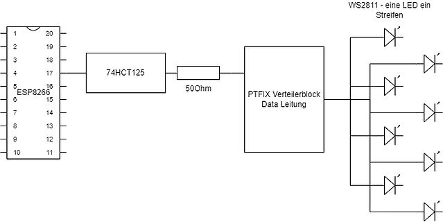
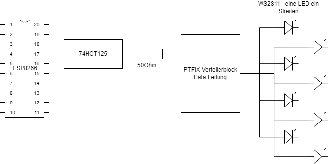
Blockschaltbild einer LED-Ansteuerung mit ESP8266
16 15 14 13 12 11 10 9 8 7 6 5 4 3 2 1 ESP8266 74HCT125 50Ohm PTFIX Verteilerblock Data Leitung WS2811 - eine LED ein Streifen
in „WS2811 Datenleitung Spannung bricht ein“ · Mikrocontroller und Digitale Elektronik · · Schaltpläne
-
Bild
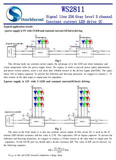
Schaltpläne für WS2811 LED-Treiber-Anwendungen
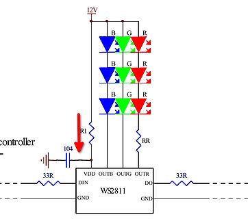
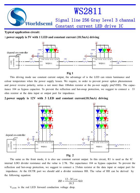
WS2811 Signal line 256 Gray level 3 channal Constant current LED drive IC 1.power supply is 5V with 1 LED and constant current (18.5mA) driving 100R 5V B G R depend on controller 33R VDD OUTB OUTG OUTR GND WS2811 GND Fig 1 2.power supply is 12V with 3 LED and constant current (18.5mA) driving 12V B G R B G R B G R R1 RR 33R VDD OUTB OUTG OUTR GND WS2811 GND Fig 2 RR = (12 - 3VLEDR) / 18.5 kOhm
in „Inhomogenes WS2811-Netzwerk“ · Mikrocontroller und Digitale Elektronik · · Screenshots
-
PDF
WS2812D_Datasheet-English.pdf
WS2812D LED 8mm RGB WS2811 LEDs There is a new addition to the popular WS2812 family of RGB LEDs with integrated controller: A 8mm through hole version. Right now they seem to be in pilot production stage. The only place that
in „"Sammelbestellung" für 8mm RGB LEDs mit WS2811 chip“ · Markt ·
-
Bild
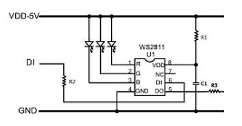
Schaltplan eines WS2811-Chips
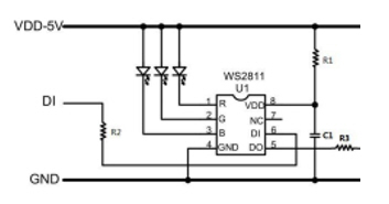
VDD-5V, DI, R2, R, G, B, WS2811, U1, VDD, NC, DI, DO, GND, R1, C1, R3
in „WS2811 - merkwürdige PWM-Ausgangssignale“ · Mikrocontroller und Digitale Elektronik · · Schaltpläne
-
Bild
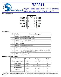
Datenblatt-Ausschnitt WS2811 LED-Treiber IC
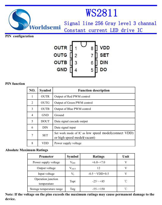
WS2811 Signal line 256 Gray level 3 channal Constant current LED drive IC PIN configuration OUTR 1 OUTG 2 OUTB 3 GND 4 VDD 8 SET 7 DIN 6 DO 5 NO. Symbol Function description 1 OUTR Output of Red PWM control
in „Inhomogenes WS2811-Netzwerk“ · Mikrocontroller und Digitale Elektronik · · Screenshots
-
Bild
Schaltplan mit WS2811 Treiber und RGB LEDs
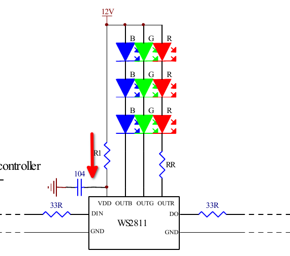
12V B G R B G R B G R R1 104 RR VDD OUTB OUTG OUTR DIN DO 33R 33R GND GND WS2811
in „WS2811 zu hoher Ruhestrom?“ · Analoge Elektronik und Schaltungstechnik · · Schaltpläne
-
Bild
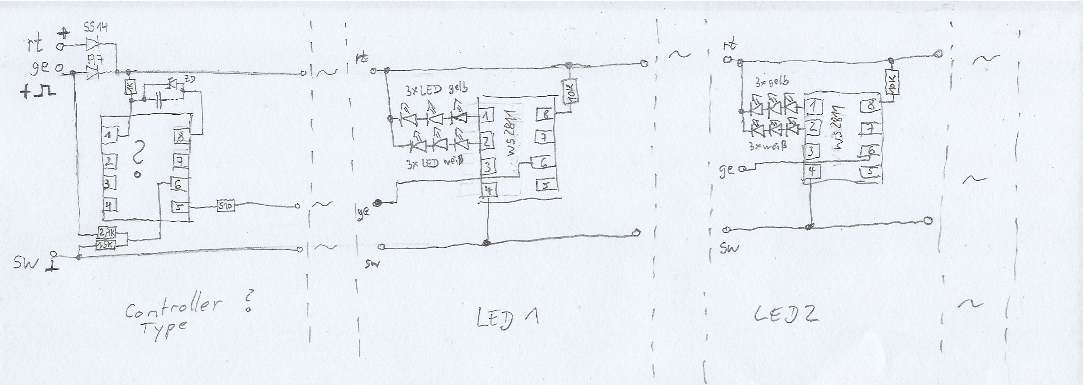
Handgezeichneter Schaltplan mit LED-Ansteuerungen
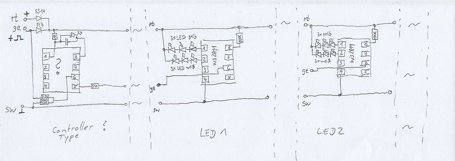
rt geo + SW SS14 2D 1 2 3 4 5 6 7 8 510 2.1K 1.5K Controller ? Type rt 3x LED gelb 10K WS2811 1 2 3 4 5 6 7 8 ge sw LED 1 3x LED weiß LED 2 rt 3x gelb 10K WS2811 1 2 3 4 5 6 7 8 3x weiß ge sw
in „LED Running Light (Contoller Typ gesucht)“ · Fahrzeugelektronik · · Schaltpläne
-
Datei
LED-Stripe_90CAN128.asm
OUT SPH,Temp OUT SPL,Temp2 Init_PORTS: LDI Temp,0b00000001 ;Bit 0 ist der Signalausgang für den WS2811/2 OUT DDRE,Temp LDI Temp,0b11111110 ;Eingänge mit Pullups versehen OUT PORTE,Temp Init_RGB_Table: LDI Counter,90 LDI XH,high(GRB_Buffer) LDI XL,low(GRB_Buffer) LDI Temp,0 Init_RGB_Loop: ST X+,Temp
in „WS2812 Ansteuerung in AVR-Assembler (ohne SPI o.ä., beliebige Pins verwendbar)“ · Projekte & Code ·
-
Datei
light_ws2812.c
/* * light weight WS2812 lib V2.0b * * Controls WS2811/WS2812/WS2812B RGB-LEDs * Author: Tim (cpldcpu@gmail.com) * * Jan 18th, 2014 v2.0b Initial Version * * License: GNU GPL v2 (see License.txt) */ #include "light_ws2812.h" #include <avr/interrupt.h>
in „ws2812 mit atmega32“ · Mikrocontroller und Digitale Elektronik ·
-
Datei
lightws.c
/* * light weight WS2812 lib V2.0b * * Controls WS2811/WS2812/WS2812B RGB-LEDs * Author: Tim (cpldcpu@gmail.com) * * Jan 18th, 2014 v2.0b Initial Version * * License: GNU GPL v2 (see License.txt) */ #include "lightws.h" #include <avr/interrupt.h> #include
in „arrays und struct in funktionen“ · Mikrocontroller und Digitale Elektronik ·
-
Datei
light_ws2812.c
/* * light weight WS2812 lib V2.0b * * Controls WS2811/WS2812/WS2812B RGB-LEDs * Author: Tim (cpldcpu@gmail.com) * * Jan 18th, 2014 v2.0b Initial Version * Nov 29th, 2015 v2.3 Added SK6812RGBW support * * License: GNU GPL v2+ (see License.txt) */ #include
in „LED-Matrix mit light_ws2812-library; Ansteuerungsgeschwindigkeit“ · Mikrocontroller und Digitale Elektronik ·
-
Datei
light_ws2812.c
/* * light weight WS2812 lib V2.0b * * Controls WS2811/WS2812/WS2812B RGB-LEDs * Author: Tim (cpldcpu@gmail.com) * * Jan 18th, 2014 v2.0b Initial Version * Nov 29th, 2015 v2.3 Added SK6812RGBW support * * License: GNU GPL v2+ (see License.txt) */ #include
in „Neopixel Attiny85 Makefile Probleme“ · Mikrocontroller und Digitale Elektronik ·
-
Datei
light_ws2812.c
/* * light weight WS2812 lib V2.0b * * Controls WS2811/WS2812/WS2812B RGB-LEDs * Author: Tim (cpldcpu@gmail.com) * * Jan 18th, 2014 v2.0b Initial Version * Nov 29th, 2015 v2.3 Added SK6812RGBW support * * License: GNU GPL v2 (see License.txt) */ #include
in „Kann mit Light WS2812 nicht mehr als 128 LEDs ansteuern“ · Mikrocontroller und Digitale Elektronik ·
-
Datei
SK6812.cpp
spec for the SK6812 but is probably too long for the WS2812 which needs a 350ns pulse for T0H This WS2811B library is free software: you can redistribute it and/or modify it under the terms of the GNU Lesser General Public License as published by the Free Software Foundation, either version 3 of the License
in „STM32 Bluepill -> SK6812 (auf Basis von WS2812B Lib)“ · Projekte & Code ·
-
Bild
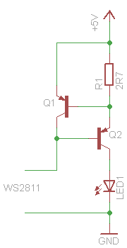
Schaltplan einer Transistor-LED-Schaltung
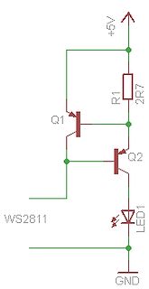
+5V, R1, 2R7, Q1, Q2, WS2811, LED1, GND
in „WS2811 Highpower LED Schaltung Verständnisfrage“ · Mikrocontroller und Digitale Elektronik · · Schaltpläne
-
Datei
LEDtestprogramm.ino
include <FastLED.h> #define NUM_LEDS 48 #define DATA_PIN 5 #define COLOUR_ORDER GRB #define LED_TYPE WS2811 CRGB leds[NUM_LEDS]; void setup() { FastLED.addLeds<LED_TYPE, DATA_PIN, COLOUR_ORDER>(leds, NUM_LEDS); for (int i = 0; i < NUM_LEDS; i++) { leds[i] = CRGB(255, 0, 0); FastLED.show(); delay(1000); }
in „Probleme WS2811 LED strip“ · Mikrocontroller und Digitale Elektronik ·
-
PDF
LED-Stripe_schematic.pdf
R 8 0 0 0 +5V R 1 R 1 R 1 IC1 8 VDD OUTR 1 7 SET OUTG 2 6 OUTB 5 C1 4 DIN DOUT 1 1 GND D 5 100n WS2811 +5V GND GND GND 5C 7 V R 4 R IC2P R 3 D 2 4 V+ V+ 3G X1 X2 1 1 8 T 2 2 R P Tmax 65°C 3 3 GND GND GND
in „LED Tube / Stromversorgung“ · Analoge Elektronik und Schaltungstechnik ·
-
Datei
WS2812.cpp
routine writes an array of bytes with RGB values to the Dataout port using the fast 800kHz clockless WS2811/2812 protocol. */ #include "WS2812.h" // Timing in ns #define w_zeropulse 350 #define w_onepulse 900 #define w_totalperiod 1250 void ws2812_init() { ws2812_DDREG |= mask; // Enable DDR } #define w_nop1
in „Ein "non bloated" arduino 328p WS2812 treiber“ · Projekte & Code ·
-
Datei
WS2812.cpp
routine writes an array of bytes with RGB values to the Dataout port using the fast 800kHz clockless WS2811/2812 protocol. Based on https://github.com/cpldcpu/light_ws2812 From Tim cpldcpu */ #include "WS2812.h" // Timing in ns #define w_zeropulse 350 #define w_onepulse 900 #define w_totalperiod 1250 void
in „Hab meinen MPP(T) akkulader probiert :)“ · Mikrocontroller und Digitale Elektronik ·
-
Datei
strandtest.ino
most NeoPixel products w/WS2812 LEDs) // NEO_KHZ400 400 KHz (classic 'v1' (not v2) FLORA pixels, WS2811 drivers) // NEO_GRB Pixels are wired for GRB bitstream (most NeoPixel products) // NEO_RGB Pixels are wired for RGB bitstream (v1 FLORA pixels, not v2) Adafruit_NeoPixel strip = Adafruit_NeoPixel(60
in „Auswahl zweier Arduino Sketches“ · Mikrocontroller und Digitale Elektronik ·
-
Datei
README.txt
=== This code provides some subroutines to drive one or more WS2812 LEDs (RGB LEDs with built-in WS2811 controller). Because the timing of the output signal is different from the standard serial protocls (RS232, SPI) supported natively by the µC, it has to be generated through another technique. There

in „AVR ASM ws2811 / ws2812 Ansteuerung mit FastPWM“ · Projekte & Code ·