-
 Bild
Bild
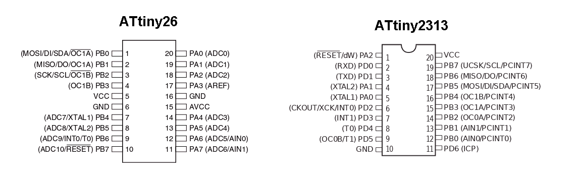
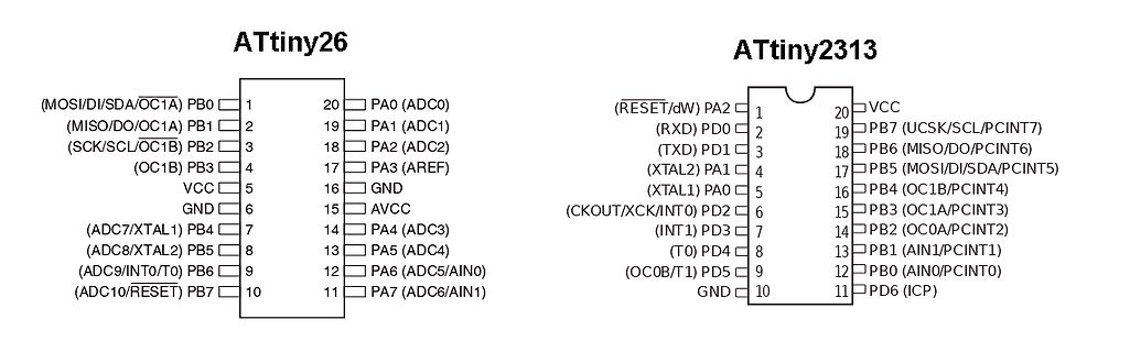
Pinbelegung ATtiny26 und ATtiny2313
ATtiny26 (MOSI/DI/SDA/OC1A) PB0 1 20 PA0 (ADC0) (MISO/DO/OC1A) PB1 2 19 PA1 (ADC1) (SCK/SCL/OC1B) PB2 3 18 PA2 (ADC2) (OC1B) PB3 4 17 PA3 (AREF) VCC 5 16 GND GND 6 15 AVCC (ADC7/XTAL1) PB4 7 14 PA4 (ADC3)
in „Suche Attiny26L-8SU (NOS)“ · Markt · · Screenshots
-
 Bild
Bild
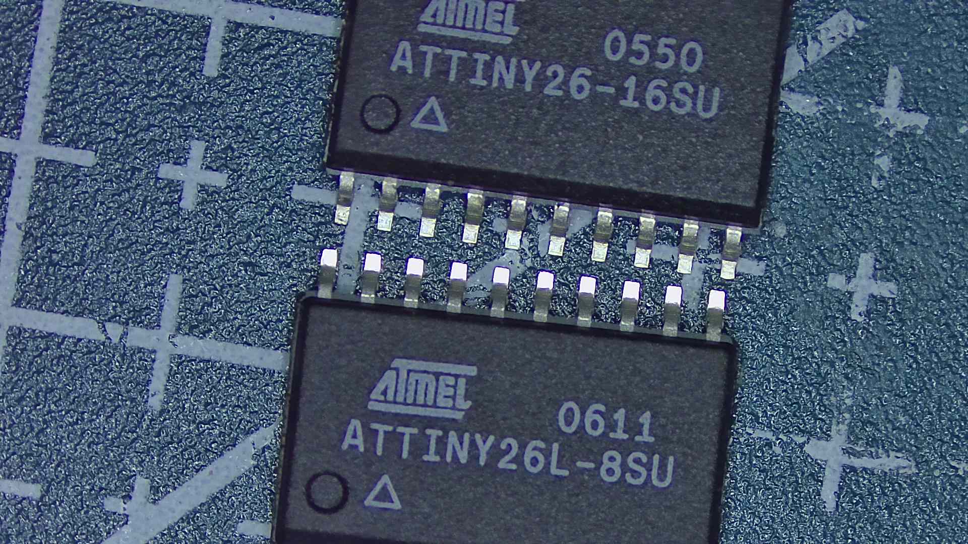
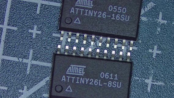
Zwei Atmel ATtiny26 Mikrocontroller
ATMEL 0550 ATtiny26-16SU ATMEL 0611 ATtiny26L-8SU
in „Suche Attiny26L-8SU (NOS)“ · Markt · · Fotos
-
PDF
ATtiny26.pdf
Programmable I/O Lines – 32-lead QFN/MLF: 16 programmable I/O Lines • Operating Voltages – 2.7V - 5.5V for ATtiny26L – 4.5V - 5.5V for ATtiny26 • Speed Grades – 0 - 8 MHz for ATtiny26L – 0 - 16 MHz for ATtiny26 • Power Consumption at 1 MHz, 3V and 25°C for ATtiny26L – Active 16 MHz, 5V and 25°C: Typ 15 mA – Active
in „ATtiny26(L) Analog-Digital-Wandler ( ADC ) Datenblattübersetzung“ · Mikrocontroller und Digitale Elektronik ·
-
Datei
attiny26_kette.c
#include <avr/io.h> #include <stdint.h> #include <util/delay.h> void warten() { for (uint8_t i=0;i<100;i++) { _delay_ms(10); } } int main (void) { DDRA=0xff; //port A als ausgänge PORTA=0xff; //Alle Pins auf hi while(1) { PORTA &= ~(1<<PA0); warten(); PORTA |= (1<<PA0); warten(); } return 0; }
in „Probleme mit ISP & AVR Studio“ · Mikrocontroller und Digitale Elektronik ·
-
Datei
attiny26_PWM.bas
$regfile = "at26def.dat" 'Man muß dem Compiler schon sagen wer drann hängt $crystal = 16000000 'Hab gerade nur nen 16 Mhz Quarz da Dim A As Byte Tccr1a = &B01010011 'Manuelle Konfiguration von OC1a Tccr1b = &B10000111 'Manuelle Konfiguration von OC1b Ddrb.0 = 1 'Port b.0 als Ausgang Ddrb.1 = 1 'Port b.1 als Ausgang Ddrb.2 = 1 'Port b.2 als Ausgang Ddrb.3 = 1 'Port b.3 als Ausgang. Do Gosub Pwm Loop Pwm: For A = 1 To 255 Ocr1c = 255 'Comparewert Ocr1a = A 'Ausgabe 1a Ocr1b = A 'Ausgabe 1b Waitms 10 'Etwas Warten damit man was mitbekommt Next Return End
in „Tiny26 PWM Problem mit Setzen des Compareregisters ?“ · Mikrocontroller und Digitale Elektronik ·
-
PDF
AVR_Uebersichtstabelle.pdf
PDIP 40 TQFP 44 ATmega88 8 0.5 1024 23 20 1.8-5.5 1 2 6 Yes 1+USART 1 Yes Yes 8 Yes Yes Yes Yes Yes 26 26 Yes MLF 32 PDIP 28 TQFP 32 ATmega88 Automotive 8 0.512 1024 23 16 2.7-5.5 1 2 6 Yes 1+USART 1 Yes Yes 8 Yes Yes Yes Yes Yes 26 26 Yes MLF 32 TQFP 32 ATtiny11 1 -- -- 6 6 2.7-5.5 -- 1 -- -- -- -- -
in „Unterschied der AVR'S“ · Mikrocontroller und Digitale Elektronik ·
-
Datei
avr.h
define ASM_SPEC "%{mmcu=*:-mmcu=%*}" #define LINK_SPEC " %{!mmcu*:-m avr2}\ %{mmcu=at90s1200|\ mmcu=attiny11|\ mmcu=attiny12|\ mmcu=attiny15|\ mmcu=attiny28:-m avr1}\ %{mmcu=attiny22|\ mmcu=attiny26|\ mmcu=at90s2*|\ mmcu=at90s4*|\ mmcu=at90s8*|\ mmcu=at90c8*|\ mmcu=at86rf401|\ mmcu=attiny13|\ mmcu=attiny2313
in „ATtiny24 - ISR wird nie gerufen __vectors> fehlt“ · Mikrocontroller und Digitale Elektronik ·
-
Datei
verlinkung.txt
ATmega8535 + * ATmega88 + * ATmega88A + * ATmega88P + # ATmega88PA + # ATmega8A - - ATmega8U2 + * ATtiny10 + * ATtiny13 - # ATtiny13A - - ATtiny1634 - - ATtiny167 + * ATtiny20 + - ATtiny2313 + - ATtiny2313A + * ATtiny24 + * ATtiny24A + * ATtiny25 + * ATtiny26 - - ATtiny261 + - ATtiny261A - # ATtiny28L + * ATtiny4 - - ATtiny40 + - ATtiny4313 + * ATtiny43U + * ATtiny44 + * ATtiny44A + * ATtiny45 - - ATtiny461 + - ATtiny461A + * ATtiny48 + * ATtiny5 - - ATtiny828 + * ATtiny84 - # ATtiny84A + * ATtiny85 + - ATtiny861
in „MC PIC - Warum diese Ungleichbehandlung?“ · Mikrocontroller und Digitale Elektronik ·
-
 Bild
Bild
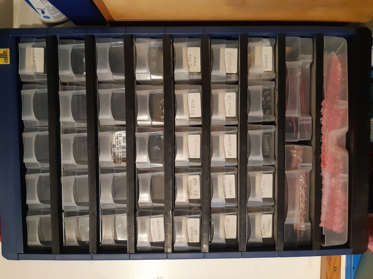
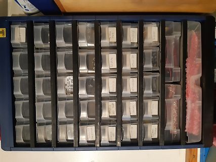
Sortierbox mit elektronischen Bauteilen
ATmega8 ATtiny25 ATtiny26 ATtiny45 ATtiny85 ATtiny13 ATtiny84 ATtiny2313 ATtiny44 ATtiny27 ATtiny45 ATtiny85 ATtiny25 ATtiny26 ATtiny45 ATtiny85 ATtiny13 ATtiny84 ATtiny2313 ATtiny44 ATtiny27 ATtiny45 ATtiny85 ATtiny25 ATtiny26 ATtiny45 ATtiny85 ATtiny13 ATtiny84 ATtiny2313 ATtiny44 ATtiny27
in „Nachlassauflösung, AVRs, Oszi, MM, Bücher, div. Bauteile“ · Markt · · Fotos
-
PDF
ATtiny841_Datasheet.pdf
SCI (PB0) High to SDO (PA4) Valid 16 ns tWLWH_PFB Wait after Instr. 3 for Write Fuse Bits 2.5 ms ATtiny441/841 [DATASHEET] 254 8495H–AVR–05/2014 26. Typical Characteristics 26.1 ATtiny441 26.1.1 Current Consumption 26.1.1.1 Active Mode Figure 26-1. Active Supply Current vs. Low Frequency (0.1 - 1.0MHz
in „TOCPMSA1 und TOCPMCOE Verhalten beim Attiny 841“ · Mikrocontroller und Digitale Elektronik ·
-
PDF
ATtiny441_841.pdf
SCI (PB0) High to SDO (PA4) Valid 16 ns tWLWH_PFB Wait after Instr. 3 for Write Fuse Bits 2.5 ms ATtiny441/841 [DATASHEET] 254 8495H–AVR–05/2014 26. Typical Characteristics 26.1 ATtiny441 26.1.1 Current Consumption 26.1.1.1 Active Mode Figure 26-1. Active Supply Current vs. Low Frequency (0.1 - 1.0MHz
in „Suche nach ATtiny mit ADC und Gain > 20x“ · Mikrocontroller und Digitale Elektronik ·
-
PDF
ATtiny841_Datasheet.pdf
SCI (PB0) High to SDO (PA4) Valid 16 ns tWLWH_PFB Wait after Instr. 3 for Write Fuse Bits 2.5 ms ATtiny441/841 [DATASHEET] 254 8495H–AVR–05/2014 26. Typical Characteristics 26.1 ATtiny441 26.1.1 Current Consumption 26.1.1.1 Active Mode Figure 26-1. Active Supply Current vs. Low Frequency (0.1 - 1.0MHz
in „sleep und Interrupt“ · Mikrocontroller und Digitale Elektronik ·
-
PDF
ATtiny841_Datasheet.pdf
SCI (PB0) High to SDO (PA4) Valid 16 ns tWLWH_PFB Wait after Instr. 3 for Write Fuse Bits 2.5 ms ATtiny441/841 [DATASHEET] 254 8495H–AVR–05/2014 26. Typical Characteristics 26.1 ATtiny441 26.1.1 Current Consumption 26.1.1.1 Active Mode Figure 26-1. Active Supply Current vs. Low Frequency (0.1 - 1.0MHz
in „Takt-Vorskalierungsregister beim Attiny841“ · Mikrocontroller und Digitale Elektronik ·
-
PDF
ATtiny26_STK500_parallel_programming.pdf
STK500 USer's Guide: ATtiny26 High Voltage Programming Page 1 of 2 ATtiny26/861 High Voltage Programming The STK500 has two headers for usage when configured for parallel programming. These two headers are labeled ‘PROG DATA’ and ‘PROG CTRL’. For the ATtiny26/861 the cable for the ‘PROG CTRL’ will have to be modified as the shown on the table and drawing below, and the cable from ‘PROG DATA’ will have to be connected to PORTA. Note: The ATtiny26/861 is
in „Kabellänge von Patchkabel auf dem STK500“ · Mikrocontroller und Digitale Elektronik ·
-
Datei
avr_sim_deviceu.pas
MISO DO AIN1 OC0B OC1A PCINT1'+ { 7 } '*PB2 SCK USCK SCL ADC1 T0 INT0 PCINT2'+ { 8 } '*VCC', {8} 'ATtiny26'+ { 1 } '*PB0 /OC1A SDA DI MOSI'+ { 2 } '*PB1 OC1A DO MISO'+ { 3 } '*PB2 /OC1B SCL SCK'+ { 4 } '*PB3 OC1B'+ { 5 } '*VCC'+ { 6 } '*GND'+ { 7 } '*PB4 XTAL1 ADC7'+ { 8 } '*PB5 XTAL2 ADC8'+ { 9 } '*PB6
-
PDF
AVR_Product_Update_M__03.pdf
-5.5 1.6 8PDIP,SOIC now ATtiny26L 2 128 128 16 - - - 1 - 2 - 11 Y I 2.7-5.5 0-8 20 PDIP,SOIC, 32 MLF now ATtiny26 2 128 128 16 - - - 1 - 2 - 11 Y I 4.5-5.5 0-16 20 PDIP,SOIC, 32 MLF now ATtiny28V 2 - 32 Registers 20 - - - - - 1
in „Atmel Familie“ · Mikrocontroller und Digitale Elektronik ·
-
PDF
AVR_Product_Update_November_2002.pdf
5.5 1.6 8PDIP,SOIC now ATtiny26L 2 128 128 16 - - - 1 - 2 - 11 Y I 2.7-5.5 0-8 20 PDIP,SOIC, 32 MLF now ATtiny26 2 128 128 16 - - - 1 - 2 - 11 Y I 4.5-5.5 0-16 20 PDIP,SOIC, 32 MLF now ATtiny28V 2 - 32Registers 20 - - - - - 1 -
in „Veraltete AVR's ?!“ · Mikrocontroller und Digitale Elektronik ·
-
PDF
Atmel_Evaluations-Board_Version_2.0.pdf
drei verschiede- ne Möglichkeiten: Die Microcontroller ATmega8535, ATmega16, ATmega32, Atmega8, Attiny 2313, Attiny12 und Attiny15 können über die ISP-Schnittstelle programmiert werden, indem sie über die serielle Schnittstelle mit dem PC verbunden werden, oder über einen ISP- Schnittstellenadapter,
in „ISP über RS232“ · Mikrocontroller und Digitale Elektronik ·
-
PDF
D810038B.PDF
drei verschiede- ne Möglichkeiten: Die Microcontroller ATmega8535, ATmega16, ATmega32, Atmega8, Attiny 2313, Attiny12 und Attiny15 können über die ISP-Schnittstelle programmiert werden, indem sie über die serielle Schnittstelle mit dem PC verbunden werden, oder über einen ISP- Schnittstellenadapter,
in „Pollin Board unzuverlässig-Hilfe bei der Fehlersuche!“ · Mikrocontroller und Digitale Elektronik ·
-
PDF
Pollin_Board.pdf
drei verschiede- ne Möglichkeiten: Die Microcontroller ATmega8535, ATmega16, ATmega32, Atmega8, Attiny 2313, Attiny12 und Attiny15 können über die ISP-Schnittstelle programmiert werden, indem sie über die serielle Schnittstelle mit dem PC verbunden werden, oder über einen ISP- Schnittstellenadapter,
in „AVR: UART Pollin Board“ · Mikrocontroller und Digitale Elektronik ·
-
PDF
D810038B.pdf
drei verschiede- ne Möglichkeiten: Die Microcontroller ATmega8535, ATmega16, ATmega32, Atmega8, Attiny 2313, Attiny12 und Attiny15 können über die ISP-Schnittstelle programmiert werden, indem sie über die serielle Schnittstelle mit dem PC verbunden werden, oder über einen ISP- Schnittstellenadapter,
-
PDF
AVR-Board20_810038B.PDF
drei verschiede- ne Möglichkeiten: Die Microcontroller ATmega8535, ATmega16, ATmega32, Atmega8, Attiny 2313, Attiny12 und Attiny15 können über die ISP-Schnittstelle programmiert werden, indem sie über die serielle Schnittstelle mit dem PC verbunden werden, oder über einen ISP- Schnittstellenadapter,
in „Atmel Evaluationboard V2.01“ · Mikrocontroller und Digitale Elektronik ·
-
PDF
pollin_board.PDF
drei verschiede- ne Möglichkeiten: Die Microcontroller ATmega8535, ATmega16, ATmega32, Atmega8, Attiny 2313, Attiny12 und Attiny15 können über die ISP-Schnittstelle programmiert werden, indem sie über die serielle Schnittstelle mit dem PC verbunden werden, oder über einen ISP- Schnittstellenadapter,
in „Atmega32 Evaluationsboard pollin mysmartusb“ · Mikrocontroller und Digitale Elektronik ·
-
PDF
D810038b_3.pdf
drei verschiede- ne Möglichkeiten: Die Microcontroller ATmega8535, ATmega16, ATmega32, Atmega8, Attiny 2313, Attiny12 und Attiny15 können über die ISP-Schnittstelle programmiert werden, indem sie über die serielle Schnittstelle mit dem PC verbunden werden, oder über einen ISP- Schnittstellenadapter,
in „richtige Hard und Software für Anfänger“ · Mikrocontroller und Digitale Elektronik ·
-
PDF
pollin_board.PDF
drei verschiede- ne Möglichkeiten: Die Microcontroller ATmega8535, ATmega16, ATmega32, Atmega8, Attiny 2313, Attiny12 und Attiny15 können über die ISP-Schnittstelle programmiert werden, indem sie über die serielle Schnittstelle mit dem PC verbunden werden, oder über einen ISP- Schnittstellenadapter,
in „Interrupt und PortC Atmega32“ · Mikrocontroller und Digitale Elektronik ·
-
PDF
STK200.pdf
- ATtiny2313 erence. Supports new ADC features of ATmega devices including differential inputs. ATtiny26 External Memory. 74HC573 address latch and Flash RAM sockets (Devices available AT90S1200 separately)
in „Wer kennt dieses AVR-Board?“ · Mikrocontroller und Digitale Elektronik ·
-
PDF
D810038B.PDF
644 • IC-Sockel DIP 28 für den MicrocontrollerATmega 8 • IC-Sockel DIP 20 für den MicrocontrollerATtiny 2313 • z wei IC-Sockel DIP 8 einmal für die MicrocontrollerATtiny 12 undATtiny 15 und zum anderen für I2C Eeproms der 24Cxx-Serie • RS232-Schnittstelle (Tx, Rx) mit Pegelanpassung über MAX232 • ein
-
PDF
D810038B.PDF
644 • IC-Sockel DIP 28 für den MicrocontrollerATmega 8 • IC-Sockel DIP 20 für den MicrocontrollerATtiny 2313 • z wei IC-Sockel DIP 8 einmal für die MicrocontrollerATtiny 12 undATtiny 15 und zum anderen für I2C Eeproms der 24Cxx-Serie • RS232-Schnittstelle (Tx, Rx) mit Pegelanpassung über MAX232 • ein
in „LCD Fusebits für Atmega32“ · Mikrocontroller und Digitale Elektronik ·
-
PDF
Pollin_AVR_Evalutationsboard.pdf
644 • IC-Sockel DIP 28 für den MicrocontrollerATmega 8 • IC-Sockel DIP 20 für den MicrocontrollerATtiny 2313 • z wei IC-Sockel DIP 8 einmal für die MicrocontrollerATtiny 12 undATtiny 15 und zum anderen für I2C Eeproms der 24Cxx-Serie • RS232-Schnittstelle (Tx, Rx) mit Pegelanpassung über MAX232 • ein
in „External Interrupt Atmega16“ · Mikrocontroller und Digitale Elektronik ·
-
PDF
Pollin_Atmel_Evaluationsboard_2.0.1.pdf
644 • IC-Sockel DIP 28 für den MicrocontrollerATmega 8 • IC-Sockel DIP 20 für den MicrocontrollerATtiny 2313 • z wei IC-Sockel DIP 8 einmal für die MicrocontrollerATtiny 12 undATtiny 15 und zum anderen für I2C Eeproms der 24Cxx-Serie • RS232-Schnittstelle (Tx, Rx) mit Pegelanpassung über MAX232 • ein
in „suche PDF zu einem älteren Pollin Eval. Board“ · Mikrocontroller und Digitale Elektronik ·
-
PDF
D810074B.pdf
644 • IC-Sockel DIP 28 für den MicrocontrollerATmega 8 • IC-Sockel DIP 20 für den MicrocontrollerATtiny 2313 • z wei IC-Sockel DIP 8 einmal für die MicrocontrollerATtiny 12 undATtiny 15 und zum anderen für I2C Eeproms der 24Cxx-Serie • RS232-Schnittstelle (Tx, Rx) mit Pegelanpassung über MAX232 • ein
in „Probleme beim Einstieg in die wunderbare Welt der Microcontroller“ · Mikrocontroller und Digitale Elektronik ·
-
PDF
Evaluationsboard.PDF
644 • IC-Sockel DIP 28 für den MicrocontrollerATmega 8 • IC-Sockel DIP 20 für den MicrocontrollerATtiny 2313 • z wei IC-Sockel DIP 8 einmal für die MicrocontrollerATtiny 12 undATtiny 15 und zum anderen für I2C Eeproms der 24Cxx-Serie • RS232-Schnittstelle (Tx, Rx) mit Pegelanpassung über MAX232 • ein
in „Atmega16 UART empfängt nicht - senden klappt“ · Mikrocontroller und Digitale Elektronik ·
-
PDF
Unterlagen_Pollinboard.pdf
644 • IC-Sockel DIP 28 für den MicrocontrollerATmega 8 • IC-Sockel DIP 20 für den MicrocontrollerATtiny 2313 • z wei IC-Sockel DIP 8 einmal für die MicrocontrollerATtiny 12 undATtiny 15 und zum anderen für I2C Eeproms der 24Cxx-Serie • RS232-Schnittstelle (Tx, Rx) mit Pegelanpassung über MAX232 • ein
in „Atmega16 keine Kommunikation“ · Mikrocontroller und Digitale Elektronik ·
-
Datei
x.txt
atmega88pa atmega8a atmega8hva atmega8u2 atmxt112sl atmxt224 atmxt224e atmxt336s atmxt540s atmxt540sreva attiny11 attiny12 attiny13 attiny13a attiny15 attiny1634 attiny167 attiny22 attiny2313 attiny2313a attiny24 attiny24a attiny25 attiny26 attiny261 attiny261a attiny28 attiny4313 attiny43u attiny44 attiny44a
in „Eclipse (mars) und AVR -- Fehlermeldungen“ · Mikrocontroller und Digitale Elektronik ·
-
PDF
Beschreibung_ATMEL_Evaluations-Board_Ver_2_0_1_von_Pollin_D810038B.pdf
644 • IC-Sockel DIP 28 für den MicrocontrollerATmega 8 • IC-Sockel DIP 20 für den MicrocontrollerATtiny 2313 • zwei IC-Sockel DIP 8 einmal für die MicrocontrollerATtiny 12 undATtiny 15 und zum anderen für I2C Eeproms der 24Cxx-Serie • RS232-Schnittstelle (Tx, Rx) mit Pegelanpassung über MAX232 • ein
in „AMTEL Evaluationsboard 2.0.1 von Pollin“ · Mikrocontroller und Digitale Elektronik ·
-
PDF
DTMF_ATTINY26a.pdf
DTMF_ATTINY26a.pdf
in „DTMF AVR314 nach mega8“ · Mikrocontroller und Digitale Elektronik ·
-
Datei
attiny26_PWM_2.bas
$regfile = "at26def.dat" 'Man muß dem Compiler schon sagen wer drann hängt $crystal = 16000000 'Hab gerade nur nen 16 Mhz Quarz da Dim A As Byte Config Timer1 = Pwm , Pwm = 8 , Compare A Pwm = Clear Down , Compare B Pwm = Clear Up , Prescale = 1 Do Gosub Pwm Loop Pwm: For A = 1 To 255 Ocr1c = 255 'Comparewert Ocr1a = A 'Ausgabe 1a Ocr1b = A 'Ausgabe 1b Waitms 10 'Etwas Warten damit man was mitbekommt Next Return End
in „Tiny26 PWM Problem mit Setzen des Compareregisters ?“ · Mikrocontroller und Digitale Elektronik ·
-
Datei
Ausgabe_von_avrdude_bei_16MHz_external.txt
verifying flash memory against C:\Windows\TEMP\build29be726e8adfdce07fcfa56b8772cd26.tmp/Test_Software_Serial_ATtiny84.ino.hex: avrdude: load data flash data from input file C:\Windows\TEMP\build29be726e8adfdce07fcfa56b8772cd26.tmp/Test_Software_Serial_ATtiny84.ino.hex: avrdude: input file C:\Windows\TEMP\build29be726e8adfdce07fcfa56b8772cd26.tmp/Test_Software_Serial_ATtiny84.ino.hex contains 2580 bytes avrdude: reading on-chip flash data: Reading | ################################################## | 100% 2.03s avrdude: verifying ... avrdude
in „ATtiny84, FTDI FT232RL, SofwareSerial.h, Arduino ISP“ · Mikrocontroller und Digitale Elektronik ·
-
Datei
dumpspecs1.txt
fstack-protector-all:-lssp_nonshared -lssp} *endfile: *link: %{!mmcu*:-m avr2}%{mmcu=at90s1200|mmcu=attiny11|mmcu=attiny12|mmcu=attiny15|mmcu=attiny28:-m avr1} %{mmcu=attiny22|mmcu=attiny26|mmcu=at90s2*|mmcu=at90s4*|mmcu=at90s8*|mmcu=at90c8*|mmcu=at86rf401|mmcu=attiny13|mmcu=attiny2313:-m avr2}%{mmcu=atmega103
in „ATtiny24 - ISR wird nie gerufen __vectors> fehlt“ · Mikrocontroller und Digitale Elektronik ·
-
PDF
ATtiny212_40001911A.pdf
second receive buffer. Datasheet Preliminary DS40001911A-page 291 © 2017 Microchip Technology Inc. ATtiny212/412 26. TWI - Two Wire Interface 26.1 Features • Bidirectional, two-wire communication interface 2 – Philips I C compatible – System Management Bus (SMBus) compatible • Bus master and slave operation
in „Neue 8-Bit Tinys vorgestellt: 417/814/816/817“ · Mikrocontroller und Digitale Elektronik ·
-
PDF
Tiny15L.pdf
the Peripheral Timer/Counter1. The nominal frequency of this peripheral clock, PCK, is 25.6 MHz. 4 ATtiny15L 1187DS–12/01 ATtiny15L ATtiny15L Register Summary Address Name Bit 7 Bit 6 Bit 5 Bit 4 Bit 3 Bit 2 Bit 1 Bit 0 Page $3F SREG I T H S V N Z C page 11 $3E Reserved $3C Reserved $3B GIMSK - INT0 PCIE
in „Frequenzschalter“ · Mikrocontroller und Digitale Elektronik ·
-
Datei
USI_TWI_Master.h
Supported devices : All device with USI module can be used. * The example is written for the ATmega169, ATtiny26 and ATtiny2313 * * AppNote : AVR310 - Using the USI module as a TWI Master * * Description : This is an implementation of an TWI master using * the USI module as basis. The implementation assumes
in „I2C ATtiny167 mit USI“ · Mikrocontroller und Digitale Elektronik ·
-
Datei
uisp.diff
uisp-patched/src/Avr.C Sat Aug 20 00:00:47 2005 @@ -49,6 +49,7 @@ TAvr::TPart TAvr::parts [] = { { "ATtiny12", 0x90, 0x05, 1024, 0, 64, 1700, 3400, AVR_TN12 }, { "ATtiny15", 0x90, 0x06, 1024, 0, 64, 2000, 4000, AVR_TN15 }, + { "ATtiny13", 0x90, 0x07, 1024, 32, 64, 1700, 3400, AVR_TN13 }, #if 0 /* 12V serial programming only; here just for the evidence */ /* ATtiny10 = QuickFlash(TM) OTP */ @@ -65,6 +66,7 @@ TAvr::TPart TAvr::parts [] = { { "ATtiny22", 0x91, 0x06, 2048, 0, 128, 4000, 4000, AVR_TN22 }, { "ATtiny26", 0x91, 0x09, 2048, 32, 128, 4500, 9000, AVR_TN26
in „Bekomme keine Daten in meinen ATtiny2313“ · Mikrocontroller und Digitale Elektronik ·
-
Datei
USI_TWI_Master.h
Supported devices : All device with USI module can be used. * The example is written for the ATmega169, ATtiny26 and ATtiny2313 * * AppNote : AVR310 - Using the USI module as a TWI Master * * Description : This is an implementation of an TWI master using * the USI module as basis. The implementation assumes
in „Hilfe! Mein AVR USI Master (I2C) mag nicht mehr :(“ · Mikrocontroller und Digitale Elektronik ·
-
Datei
Ausgabe_von_avrdude_bei_8MHz_internal.txt
verifying flash memory against C:\Windows\TEMP\build29be726e8adfdce07fcfa56b8772cd26.tmp/Test_Software_Serial_ATtiny84.ino.hex: avrdude: load data flash data from input file C:\Windows\TEMP\build29be726e8adfdce07fcfa56b8772cd26.tmp/Test_Software_Serial_ATtiny84.ino.hex: avrdude: input file C:\Windows\TEMP\build29be726e8adfdce07fcfa56b8772cd26.tmp/Test_Software_Serial_ATtiny84.ino.hex contains 2580 bytes avrdude: reading on-chip flash data: Reading | ################################################## | 100% 1.89s avrdude: verifying ... avrdude
in „ATtiny84, FTDI FT232RL, SofwareSerial.h, Arduino ISP“ · Mikrocontroller und Digitale Elektronik ·
-
Datei
USI_TWI_Master.h
Supported devices : All device with USI module can be used. * The example is written for the ATmega169, ATtiny26 and ATtiny2313 * * AppNote : AVR310 - Using the USI module as a TWI Master * * Description : This is an implementation of an TWI master using * the USI module as basis. The implementation assumes
in „TWI mit USI nach AN-310“ · Mikrocontroller und Digitale Elektronik ·
-
Datei
USI_TWI_Master.h
Supported devices : All device with USI module can be used. * The example is written for the ATmega169, ATtiny26 and ATtiny2313 * * AppNote : AVR310 - Using the USI module as a TWI Master * * Description : This is an implementation of an TWI master using * the USI module as basis. The implementation assumes
in „C-Code optimieren (passt nicht in Attiny2313) :(“ · Mikrocontroller und Digitale Elektronik ·
-
Datei
USI_TWI_Master.h
Supported devices : All device with USI module can be used. * The example is written for the ATmega169, ATtiny26 and ATtiny2313 * * AppNote : AVR310 - Using the USI module as a TWI Master * * Description : This is an implementation of an TWI master using * the USI module as basis. The implementation assumes
in „Attiny 2313A - ROM am Limit? Probleme mit Optimierer“ · Mikrocontroller und Digitale Elektronik ·
-
Datei
USI_TWI_Master.h
Supported devices : All device with USI module can be used. * The example is written for the ATmega169, ATtiny26 and ATtiny2313 * * AppNote : AVR310 - Using the USI module as a TWI Master * * Description : This is an implementation of an TWI master using * the USI module as basis. The implementation assumes
in „Attiny 2313A - ROM am Limit? Probleme mit Optimierer“ · Mikrocontroller und Digitale Elektronik ·
-
Datei
beispiel.html
</b></span> - <span style="color: blue;"><b> ATTINY25-45-85/DIP-SO </b></span> - <span style="color: blue;"><b> ATTINY25-45-85/QFN-MLF </b></span> - <span style="color: blue;"><b> ATTINY26DIP/SO </b></span> - <span style="color: blue;"><b> ATTINY26MLF
in „[KiCad] Bibliotheksaufbau - Konzeptideen gesucht“ · Platinen ·