-
Bild
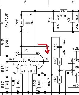
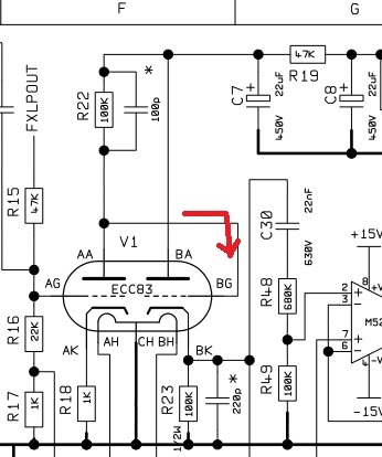
Ausschnitt eines Schaltplans mit ECC83 Röhre
F G FXLPOUT R22 100K * 100p C7 22uF R19 47K C8 22uF R15 47K V1 AA AG ECC83 BA BG C30 22nF 630V R48 680K +15V R16 22K AK AH CH BH BK R23 100K * 220p R18 1K R17 1K R49 100K 7 6 -15V
in „Verständnis ECC83 / Gitarrenverstärker“ · Analoge Elektronik und Schaltungstechnik · · Schaltpläne
-
Bild
Schaltplan eines Röhrenverstärkers mit ECC83 und ECL86
TARGET:T3001 V32 economy - [Schaltplan C:\Users\lob\475\Desktop\T3001\ECC83 Endstufe.T3001 Seite 1 "unbenannt"] Datei Bearbeiten Ansicht Elemente Bauteile Module Aktionen Fenster Einstellungen Hilfe Neue Version verfügbar: V32 Einstellungen ECC 83 ECL86 47k 0.33uF 220k 100k
in „T3001 schaltung aus ECLL800 endstufe. Die Röhren ECLL800 nicht T3001 geladen.“ · Platinen · · Screenshots
-
Bild
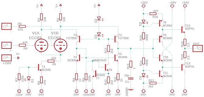
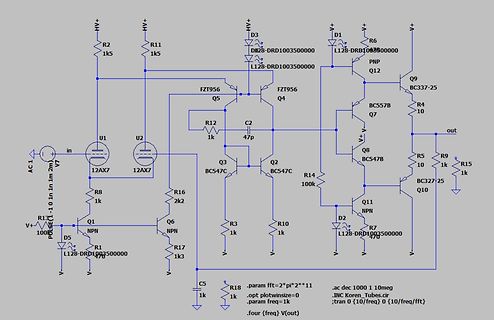
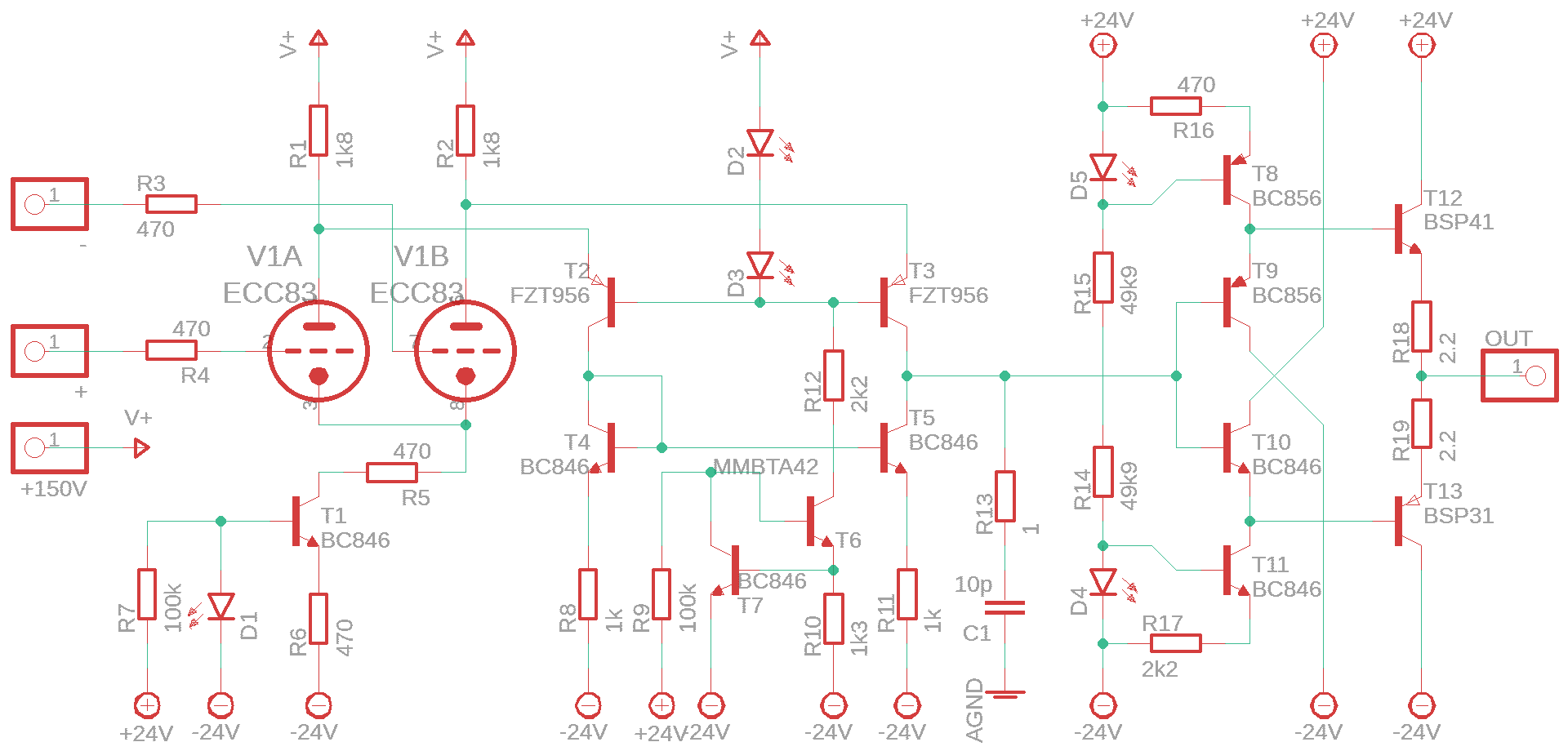
Schaltplan einer Röhren-Transistor-Stufe
V+ R1 1k8 R2 1k8 D2 D3 T3 T2 FZT956 V1A ECC83 V1B ECC83 R3 470 R4 470 + V+ +150V R5 470 T1 BC846 R6 470 R7 100k D1 +24V -24V -24V R8 1k R9 100k T4 BC846 T7 BC846 T6 BC846 R10 1k3 R11 1k R12 2k2 T5 R13 1 C1 10p AGND D4 D5 R14 49k R15 49k R16 470
in „Ein Operationsverstärker mit Röhren-Diff-Amp (ECC83)“ · Analoge Elektronik und Schaltungstechnik · · Schaltpläne
-
Bild
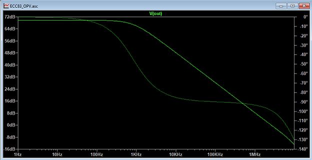
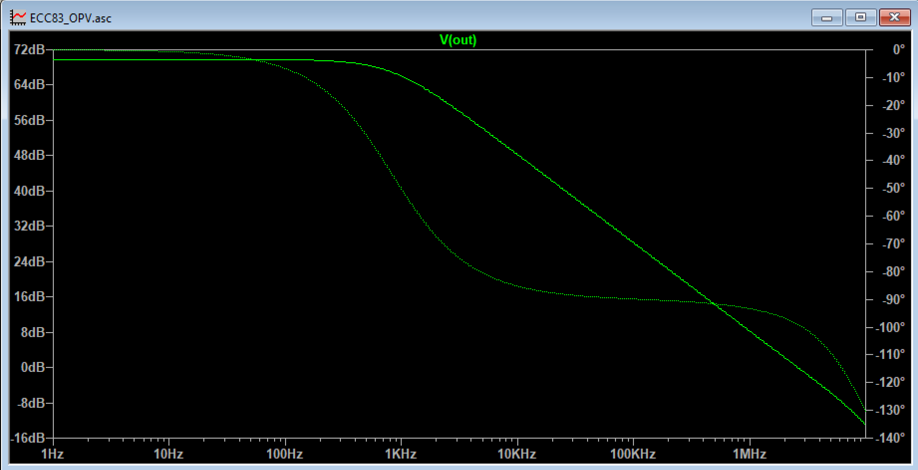
Bode-Diagramm eines Operationsverstärkers
ECC83_OPV.asc V(out) 72dB 64dB 56dB 48dB 40dB 32dB 24dB 16dB 8dB 0dB -8dB -16dB 1Hz 10Hz 100Hz 1kHz 10kHz 100kHz 1MHz 0° -10° -20° -30° -40° -50° -60° -70° -80° -90° -100° -110° -120° -130° -140°
in „Ein Operationsverstärker mit Röhren-Diff-Amp (ECC83)“ · Analoge Elektronik und Schaltungstechnik · · Screenshots
-
Bild
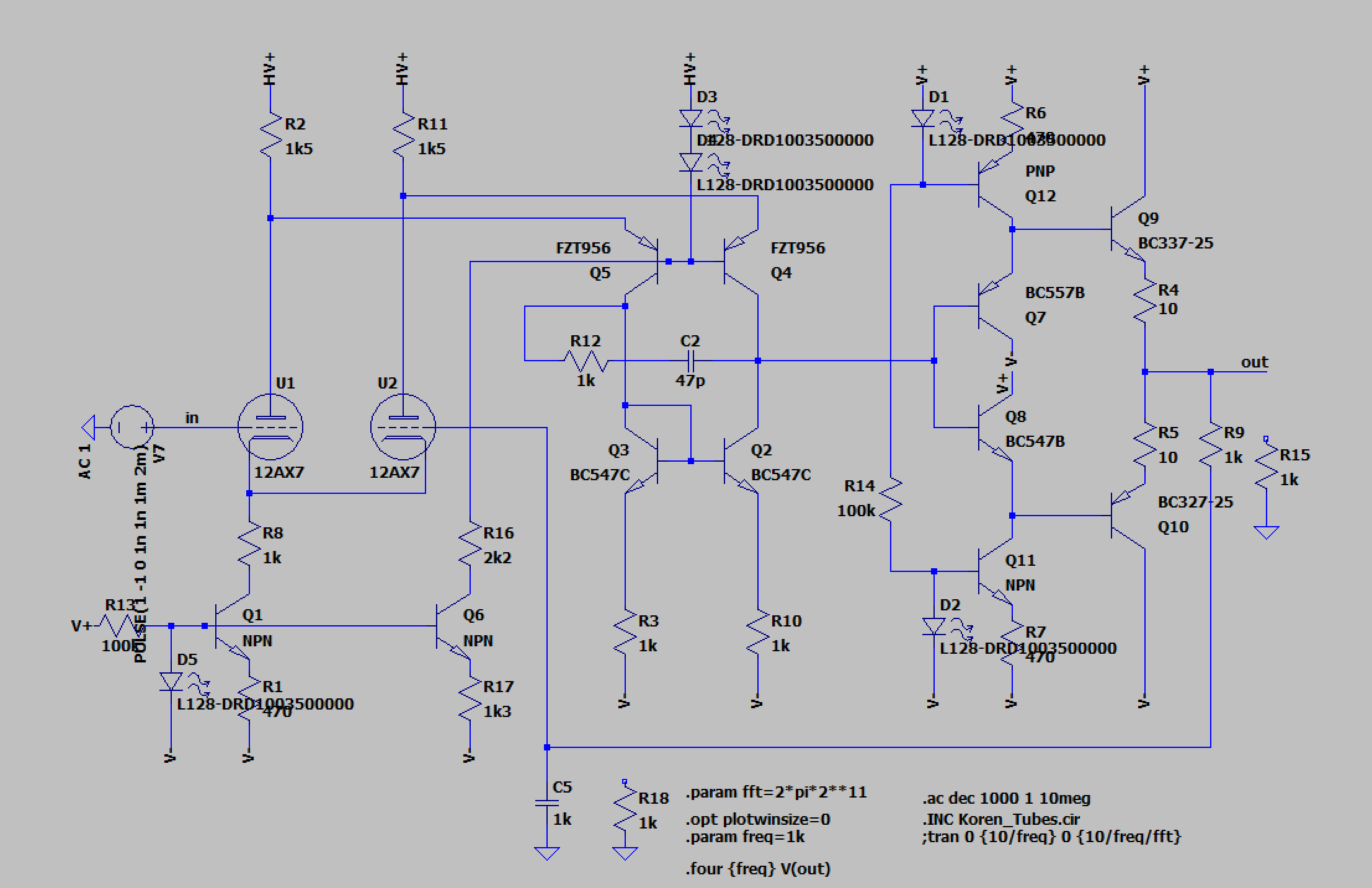
Schaltplan einer Röhrenverstärker-Schaltung
HV+ R2 1k5 R11 1k5 D3 DRB-DRD1003500000 D1 R6 L28-DRD1003500000 V+ V+ V+ PNP Q12 BC337-25 Q9 Q7 BC557B R4 10 out Q R5 10 R15 1k Q10 BC327 25 V- V- V- Q8 BC547B Q11 NPN R7 470 D2 L28-DRD1003500000 R14 100k Q2 BC547C Q3 BC547C C2 47p R3 1k R10 1k Q4 FZT956 Q5 FZT956 R12 1k U2 12AX7 U1 12AX7 in AC 1 V7 R8 1k Q1 NPN R13 100 R1 BC547C D5 L28-DRD1003500000 V+ R16 2k2 Q6 NPN R17 1k3 C5 R18 1k .param fft=2*pi*2*11 .ac dec 1000 1 10meg .INC Koren_Tubes.cir .opt plotwinsize=0 .tran 0 {10/freq} 0 {10/freq/fft} V-
in „Ein Operationsverstärker mit Röhren-Diff-Amp (ECC83)“ · Analoge Elektronik und Schaltungstechnik · · Schaltpläne
-
PDF
ECC83-Betriebswerte.pdf
in „Röhrenverstärker Berechnen“ · Analoge Elektronik und Schaltungstechnik ·
-
PDF
Elektor.pdf
, for exam- R d 000063 - 11 ple, is fitted with ECC81, ECC82, R iR ⋅ k+( ) ECC83, ECC88 or similar valves. The ECC83 has a high no-load gain, but With the following typical values for Figure 1. A standard valve preamplifier configuration using one ECC83
in „Röhrenverstärkerstufe ECC XX welches System zuerst?“ · Analoge Elektronik und Schaltungstechnik ·
-
PDF
CEPT-Laenderliste_2014.pdf
www.raag.org/displayITM1.asp?ITMID=11&LANG=EN (Stand: Italien 4.2.11) Frequenzen: 135,7–137,8 kHz; 1,83–1,85; 3,5–3,8; 7–7,2; 10,1–10,15; 14–14,35; 18,068–18,168; 21–21,45; 24,89–24,99; 28–29,7; 50–51; 144–146; 430–434, 435–438 MHz; 1,24–1,245, 1,267–1,298; 2,3–2,45; 5,65–5,67, 5,76–5,77, 5,83– Großbritannien
-
Bild
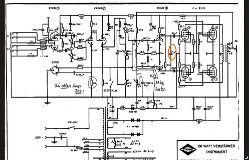
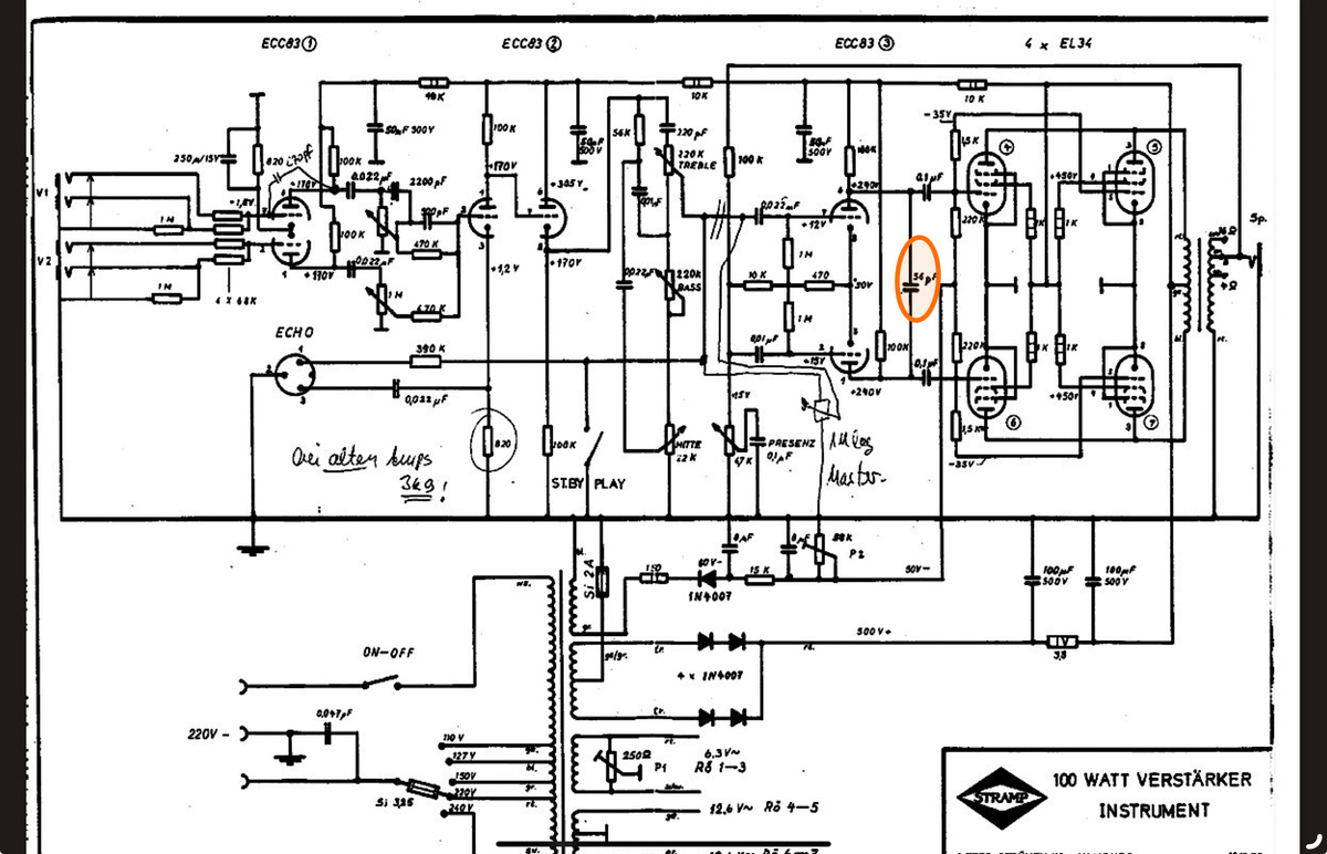
Schaltplan eines 100 Watt Verstärkers
ECC83 (1) ECC83 (2) ECC83 (3) 4 x EL34 250uF/15V 10K 10K 10K 100K 100K 100K 170V 170V 170V 35V 10K 450V 100K 10K 10K 10K
in „STRAMP 2100A“ · Analoge Elektronik und Schaltungstechnik · · Schaltpläne
-
Bild
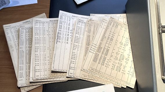
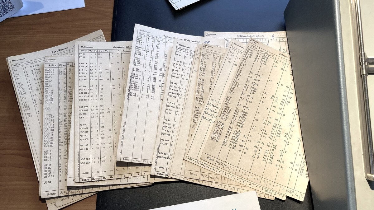
Tabellen mit Bauteilbezeichnungen und Werten
Röhre Ua Us Ub U1 2 3 4 5 6 7 8 9 10 Zahlen-Tabelle (Telefonfunktion) EPC 84 ECC 83 ECC 88 ECC 89 ECC 90 ECC 91 ECC 92 ECC 93 ECC 94 ECC 95 ECC 96 ECC 97 ECC 98 ECC 99 UBL 1 UBL 2 UBL 3 UBL 4 UBL 5 UBL 6 UBL 7 UBL 8 UBL 9 UBL 10 UFM 11 UFM 12 UFM 13 UFM 14 UFM 15
in „Röhrentester Eigenbau“ · Analoge Elektronik und Schaltungstechnik · · Fotos
-
Bild
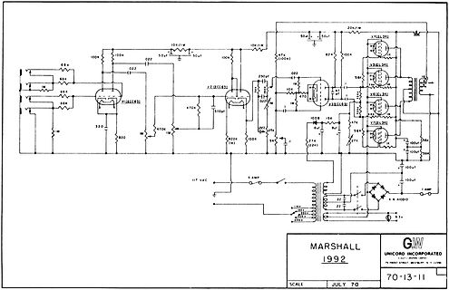
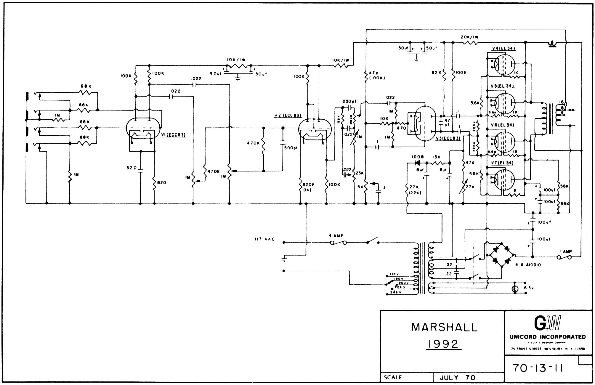
Schaltplan eines Verstärkers
MARSHALL 1992 G W UNICORD INCORPORATED 75 FROST STREET WESTBURY NY 11590 SCALE JULY 70 70-13-11 V1(ECC83) V2(ECC83) V3(ECC83) V4(EL34) V5(EL34) V6(EL34) V7(EL34) IT
in „STRAMP 2100A“ · Analoge Elektronik und Schaltungstechnik · · Schaltpläne
-
Datei
dmtriodep.inc
* 3CX300 [3.1, 05/01/1998 ] * SV6AS7 [3.0, 30/12/1997 ] * 6BM8 / ECL82 [3.0, 31/12/1997 ] * 6DJ8 / ECC88 [3.0, 15/08/1998 ] * 6N1P [3.0, 25/01/1998 ] * 6SN7GTB [3.1, 05/01/1998 ] * 12AT7 / ECC81 [3.1, 05/01/1998 ] * 12AU7 / ECC82 [3.2, 01/05/2002 ] * 12AX7 / ECC83 [3.0, 30/12/1997 ] * 76 [3.0, 12/02/
in „300V Längsregler, Transistor gefährdet?“ · Analoge Elektronik und Schaltungstechnik ·
-
Datei
dmtriodep.inc
* 3CX300 [3.1, 05/01/1998 ] * SV6AS7 [3.0, 30/12/1997 ] * 6BM8 / ECL82 [3.0, 31/12/1997 ] * 6DJ8 / ECC88 [3.0, 15/08/1998 ] * 6N1P [3.0, 25/01/1998 ] * 6SN7GTB [3.1, 05/01/1998 ] * 12AT7 / ECC81 [3.1, 05/01/1998 ] * 12AU7 / ECC82 [3.2, 01/05/2002 ] * 12AX7 / ECC83 [3.0, 30/12/1997 ] * 76 [3.0, 12/02/
in „300V Längsregler, Transistor gefährdet?“ · Analoge Elektronik und Schaltungstechnik ·
-
Datei
dmtriodep.inc
* 3CX300 [3.1, 05/01/1998 ] * SV6AS7 [3.0, 30/12/1997 ] * 6BM8 / ECL82 [3.0, 31/12/1997 ] * 6DJ8 / ECC88 [3.0, 15/08/1998 ] * 6N1P [3.0, 25/01/1998 ] * 6SN7GTB [3.1, 05/01/1998 ] * 12AT7 / ECC81 [3.1, 05/01/1998 ] * 12AU7 / ECC82 [3.2, 01/05/2002 ] * 12AX7 / ECC83 [3.0, 30/12/1997 ] * 76 [3.0, 12/02/
in „Trioden / Tetroden im Schaltbetrieb“ · HF, Funk und Felder ·
-
PDF
Roehrenliste.pdf
EB41 gebraucht 4,00 € 56 1 Valvo EBC41 gebraucht 4,00 € 57 1 Valvo EBC41 NOS 6,00 € 58 1 SEL Lorenz ECC40 NOS 10,00 € 59 2 Valvo ECC40 NOS 10,00 € 60 1 Ei Yugoslavia ECC83 NOS 4,00 € 61 1 (Rußland) ECC83 NOS 4,00 € 62 1 Valvo ECC85 (? - teilweise lesbar)NOS 10,00 € 63 1 (unlesbar) ECH41 gebraucht 5,00
in „[V] Viele Elektronenröhren / Senderöhren / Röhren (Viel NOS, BW-Bestand)“ · Markt ·
-
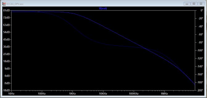
Bild
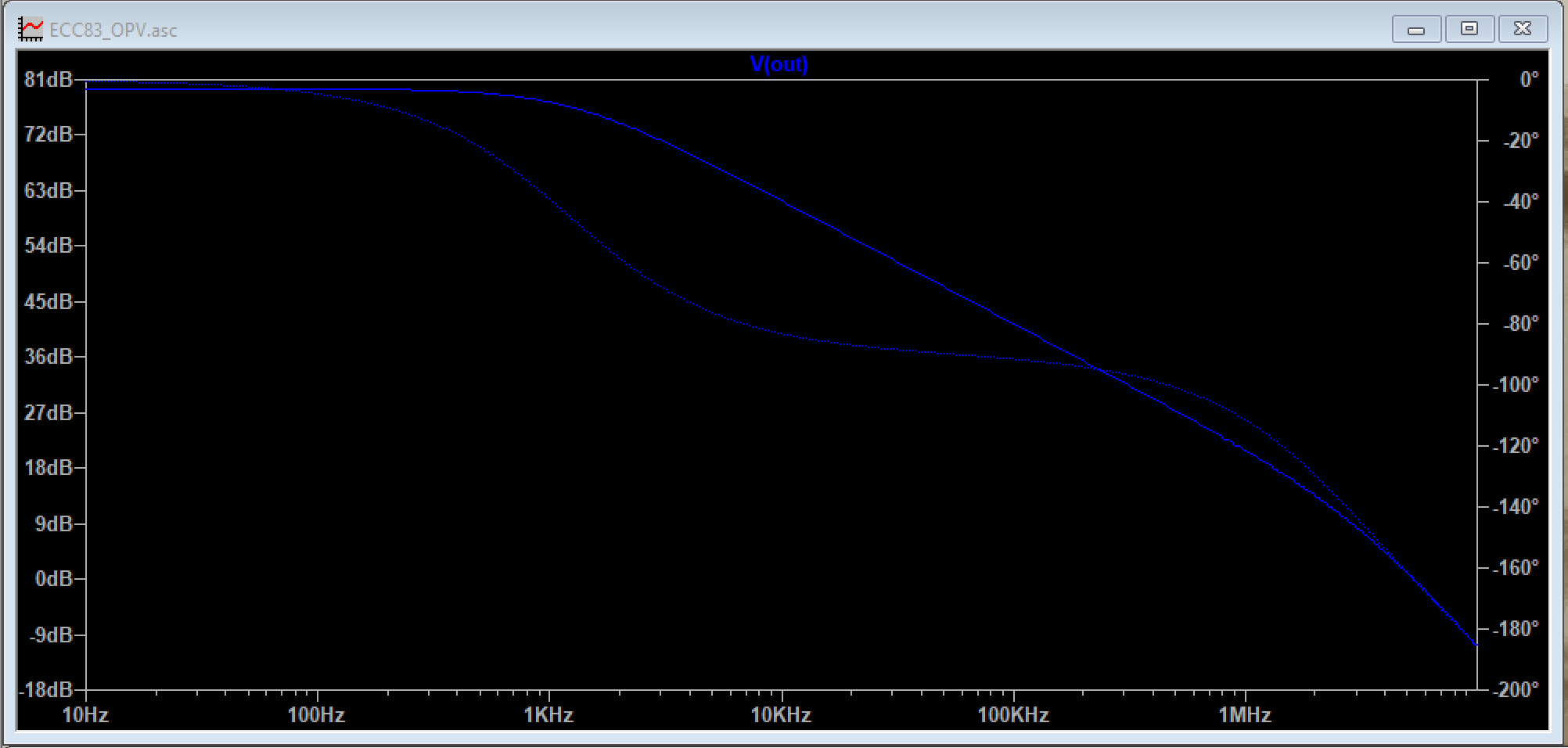
Bode-Diagramm einer Verstärkerstufe
ECC83_OPV.asc V(out) 81dB 72dB 63dB 54dB 45dB 36dB 27dB 18dB 9dB 0dB -9dB -18dB 10Hz 100Hz 1KHz 10KHz 100KHz 1MHz 0° -20° -40° -60° -80° -100° -120° -140° -160° -180° -200°
in „Ein Operationsverstärker mit Röhren-Diff-Amp (ECC83)“ · Analoge Elektronik und Schaltungstechnik · · Screenshots
-
Datei
compile_kicad_mw_debug.txt
-- Installing: /usr/local/share/kicad/demos/ecc83/ecc83-pp.net -- Installing: /usr/local/share/kicad/demos/ecc83/ecc83-pp.sch -- Installing: /usr/local/share/kicad/demos/ecc83/ecc83-pp_v2-cache.lib -- Installing: /usr/local/share/kicad/demos/ecc83/ecc83_schlib.dcm -- Installing: /usr/local/share/kicad/demos/ecc83/ecc83-pp.kicad_pcb -- Installing: /usr/local/share/kicad/demos/ecc83/ecc83-pp-cache.lib -- Installing: /usr/local/share/kicad/demos/ecc83
in „KiCad 5.0.2 - Absturz beim Footprint-Editor Aufruf“ · Platinen ·
-
PDF
Roehren.pdf
EF80 9 EF85 4 EF89 3 EF184 1 EF8X 1 EL80 1 EL84 3 EM80 1 EM84 1 EY86 1 EZ80 3 EZ81 1 EBF80 2 EBF89 3 ECC82 1 ECC83 1 ECC8X 1 ECH81 3 ECH84 5 ECL80 1 EABC80 2 Miniaturröhren Heizspannung 6,3V AC Typ Anzahl EC92 3 EL95 1 EAA91 2 Rimlockröhren Heizspannung 6,3V AC Typ Anzahl EF43 1 EL41 1 EAF42 3 ECH42 2
-
PDF
CY7C68016A.pdf
to ECCRESET, then pass data across the 16 24LC00 [9] N/A N/A N/A GPIF or Slave FIFO interface. The ECC for the first 256 bytes of data will be calculated and stored in ECC1. The ECC for the 128 24LC01 0 0 0 next 256 bytes will be stored in ECC2. After the second ECC is calculated, the values in the ECCx
in „CY7C68013A-56pins“ · Mikrocontroller und Digitale Elektronik ·
-
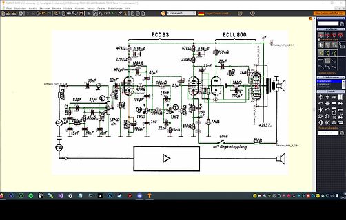
Bild
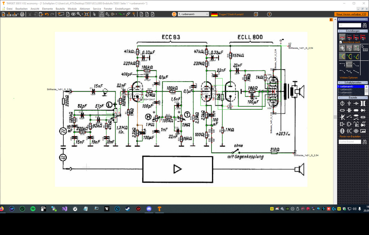
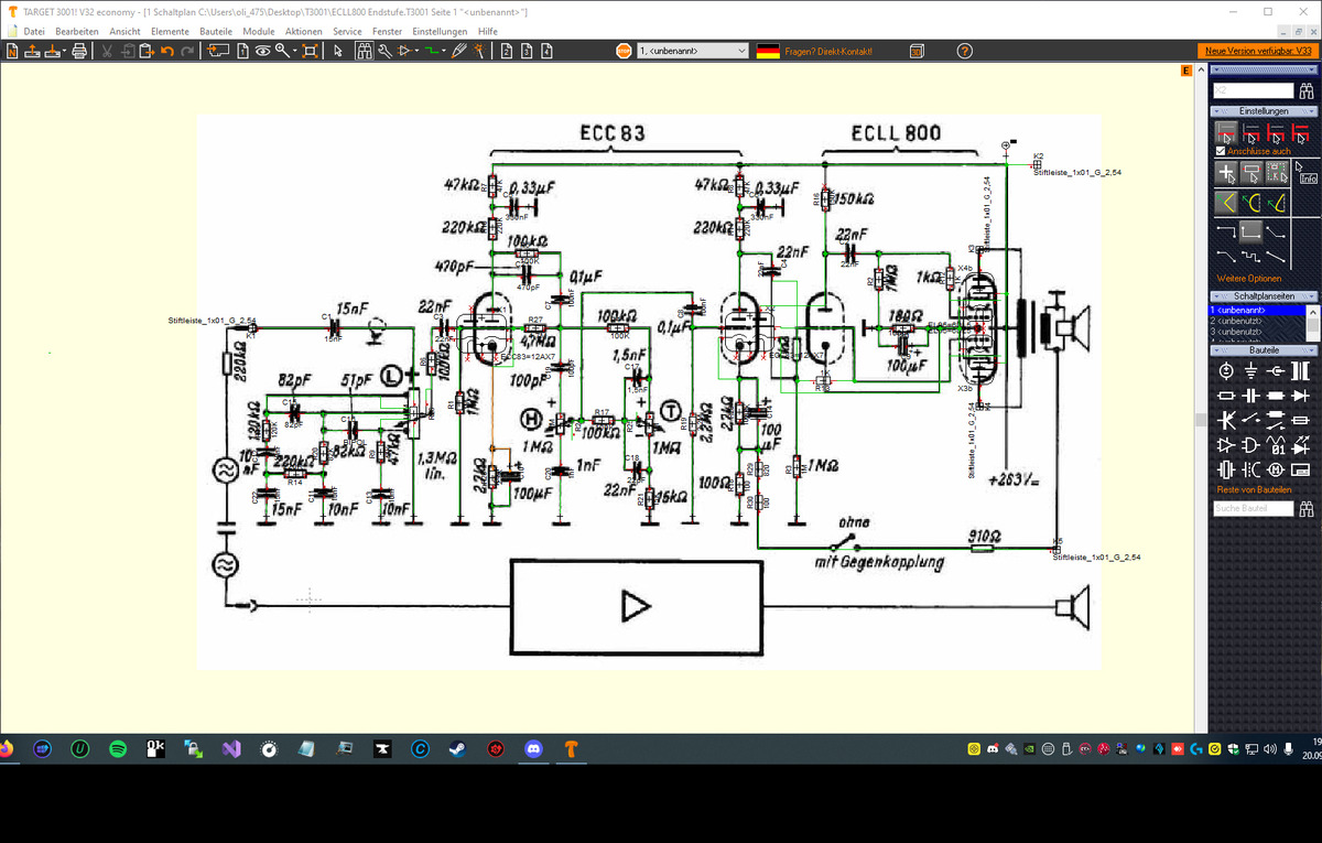
Schaltplan eines Röhrenverstärkers
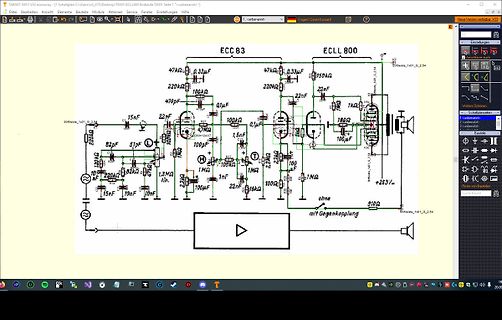
TARGET T3001 V32 economy - [Schaltplan C:\Users\lob\475\Desktop\T3001 ECC83 Endstufe.T3001 Seite 1 "unbenannt"] Datei Bearbeiten Ansicht Elemente Bauteile Module Aktionen Fenster Einstellungen Hilfe Neue Version verfügbar: V32 ECC 83 ECLL 800 47k 0.33uF 220k 100k 470pF 22nF
in „T3001 schaltung aus ECLL800 endstufe. Die Röhren ECLL800 nicht T3001 geladen.“ · Platinen · · Screenshots
-
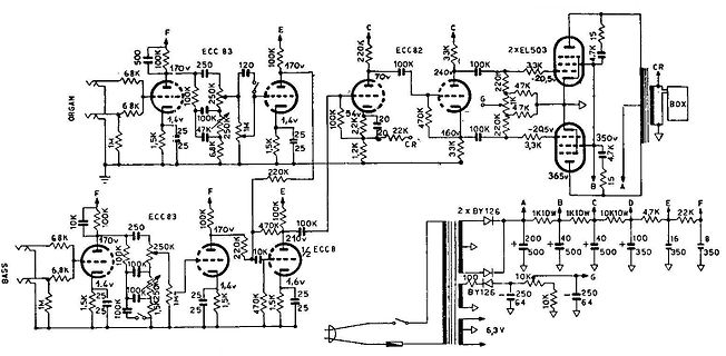
Bild
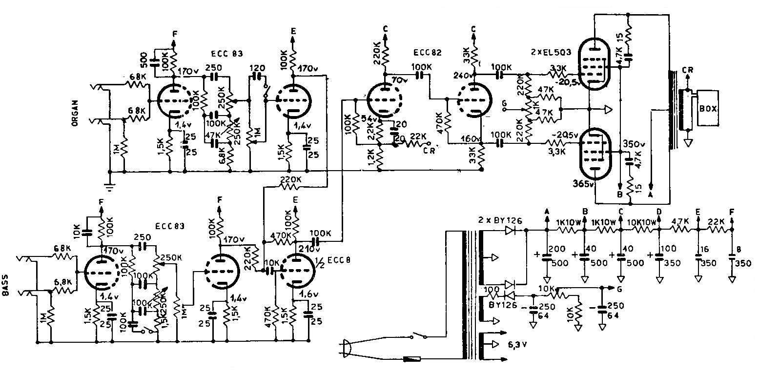
Schaltplan eines Röhrenverstärkers
ORGAN, ECC 83, 500, 170v, 250, 120, 68K, 68K, 1M, 1,4V, 1,5K, 25, 100K, 47K, 250K, 25, 1,4V, 100K, 170V, 220K, 220K, 22K, 20,5V, 2XEL503, 33K, 47K, 100K, 240V, 220V, 37K, 37K, 160V, 205V, 350V, 3,3K, 365V, 4,7K, 15, CR, BOX, BASS, ECC 83, 10K, 6,8K, 1M, 1,4V, 1,5K, 25, 100K, 250, 170V, 25, 100K, 250K, 1,4V, 2,2K, 10K, 100K, 470K, 210, 1,6V, 25, 25, 25, 22K, 1,6V, 25, BY126, 1K10W, 1K10W, 10K10W, 47K, 22K, 200, 40, 40, 100, 16, 350
in „VLF mit ECC 82“ · HF, Funk und Felder · · Schaltpläne
-
PDF
Wellenplan-1926.pdf
voce e in iscritto a) 1,2,., 100, 99 .,. 23 ventitre, venti milioni 1. b) 2, 4, 6 ., . 100, 98, 96 ecc. c) 3, 6, 9 ... e poi di 24 tre un miliardo ritorno. d) 4, 8, 12 ... e poi di ritorno. e) scrivete, 25 ventiquattro due miliardi poi leggete alcune Serie di numeri di due, tre quat- venticinque un bilione
-
PDF
SmartMedia_Format.pdf
,1 Cluster) Product Planning & Application Engineering The Leader in Memory Technology ELECTRONICS ECC Code Generode eneration ethod ♦ ECC code consists of 3 Bytes per 256 Bytes(Hamming Code ECC Algo ) - Actually 22 bit ECC code per 2048 bits - 22 bit ECC code = 16 bit line parity + 6 bit column parity ♦ Error Detection Sequence Generating and writing ECC code ECC code in Flash Memory (22 bits) during program operation (XOR) Generating New ECC code during read data area New generated ECC code during read XOR original ECC code with new generated ECC code
in „Smartcard-Reader“ · Mikrocontroller und Digitale Elektronik ·
-
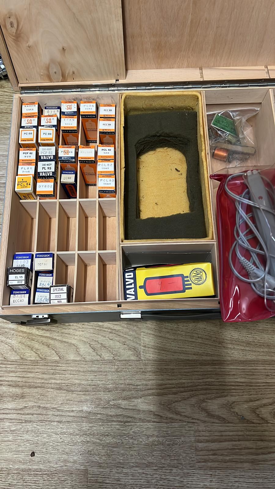
Bild
Holzkiste mit Röhrenverpackungen und Zubehör
TUNG-SOL, PCC 88, PCC 82, VALVO, PCL 82, SPECIAL, HOGES, EL 95, ECC83, ECC82
in „Preisfindung für Röhrensortiment“ · Markt · · Fotos
-
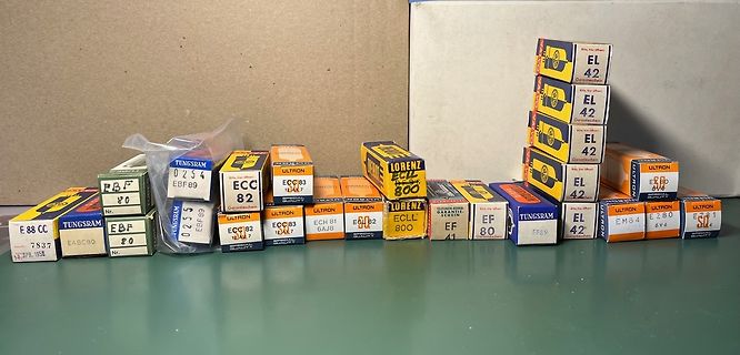
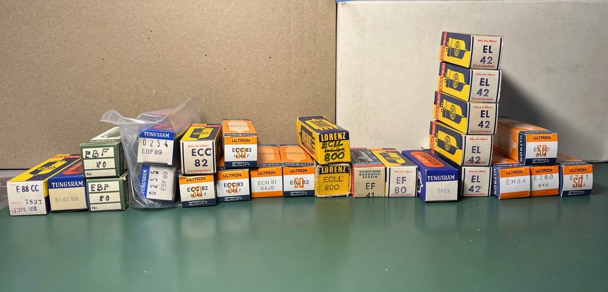
Bild
Sammlung alter Elektronikbauteil-Schachteln
TUNGSRAM EBF 80, ECC 82, ULTRON ECC 83, ECH 81, ECH 82, LORENZ ECL 800, EF 41, EF 80, TUNGSRAM EL 42, ULTRON EM 84, ULTRON EZ 80, ECH 81 6AJ8, 12JAN 7, 7S37, 12.APR. 1958
in „Verschiedene Röhren zu verkaufen“ · Markt · · Fotos
-
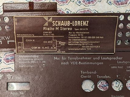
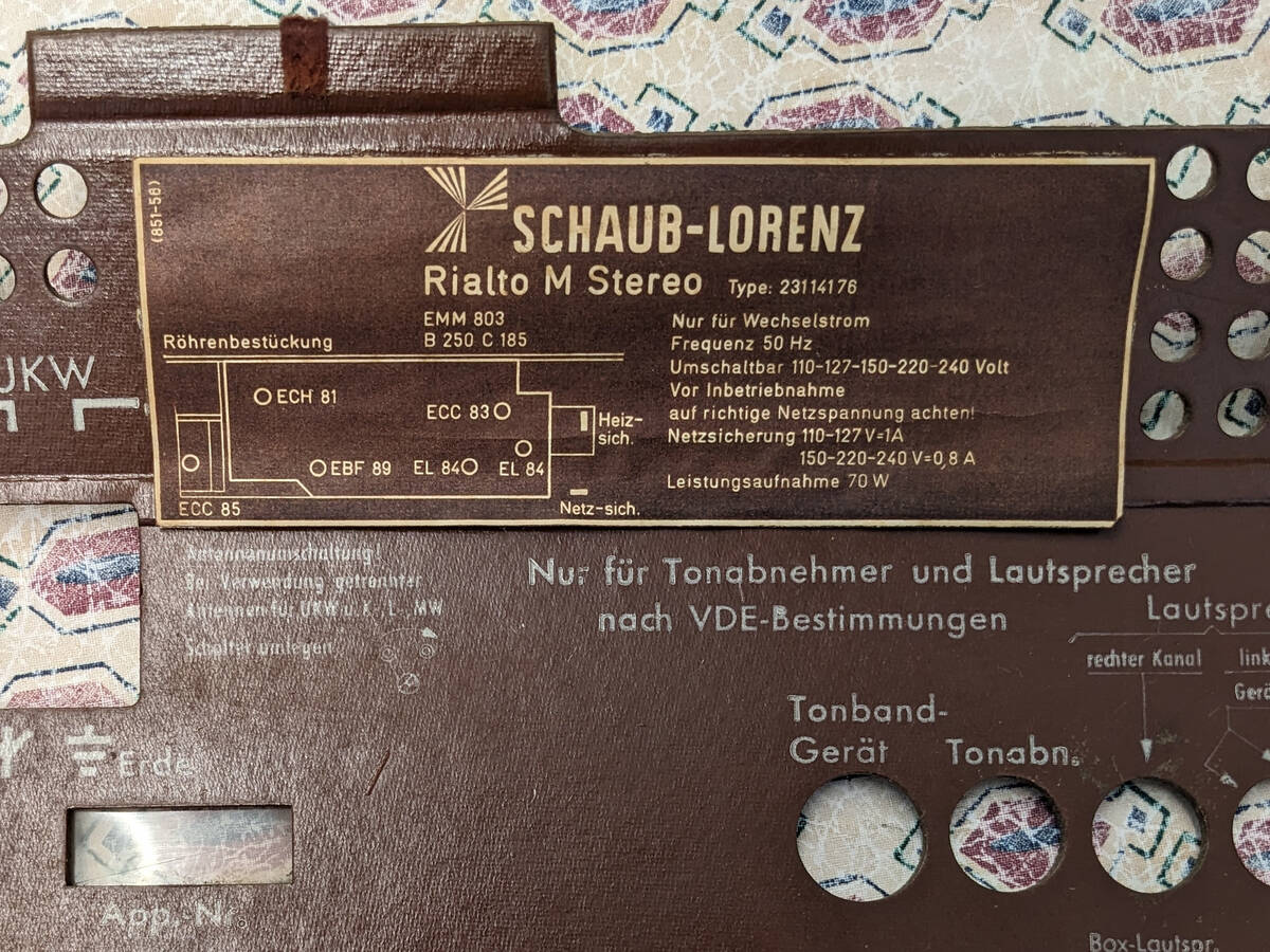
Bild
Typenschild eines Schaub-Lorenz Rialto M Stereo Radios
SCHAUB-LORENZ Rialto M Stereo Type: 23114176 Röhrenbestückung EMM 803, B 250 C 185, O ECH 81, ECC 83 O, ECC 85, O EBF 89, EL 84, EL 84 Nur für Wechselstrom Frequenz 50 Hz Umschaltbar 110-120-127-150-220-240 Volt Vor Inbetriebnahme auf richtige Netzspannung achten! Heizsich. Netzsich. 150-240 V=0,8
in „Dachbodenfund altes Schaub Lorenz Radio“ · Offtopic · · Fotos
-
PDF
Kuhschwanz.pdf
haben wir beim oberen End-Anschlag des Pot einen Teiler aus 200k zu 1,01M, was einem Verhältnis von 83,5% entspricht. Zur Erinnerung, die Höhen werden mit 5% Verhältnis geteilt. Am unteren Ende des Pot haben wir für Gleichstrom einen Teiler von 1,2M zu 10k, was 0,83% entspricht. Gegenüber den Höhen mit
in „Kuhschwanz vs Linkwitz-Riley“ · Analoge Elektronik und Schaltungstechnik ·
-
Datei
mso5202d.txt
registered (default) io scheduler cfq registered s3c-fb s3c-fb: window 0: fb s3c-fb s3c-fb: LCD type is TN83 800*480, default_bpp=16, pixclock=5 s3c-fb s3c-fb: window 1: fb s3c-fb s3c-fb: LCD type is TN83 800*480, default_bpp=16, pixclock=5 s3c2440-uart.0: ttySAC0 at MMIO 0x50000000 (irq = 70) is a S3C2440
in „Tekway/Hantek/Voltcraft MSO“ · Mikrocontroller und Digitale Elektronik ·
-
Datei
n1.out.txt
1b82684a73b18fab310d6a2991ea0cfa haval_160_3 524c01c114b8e3258acefb9339783600d97aa32a haval_160_4 bef91e50844b782ca667d83a83a60dcd60b6ea33 haval_160_5 bfc085047a178098f69140a64f3f5364092109a1 haval_192_3 81cb7b996d74572630912f04aec66dfde4bbd1d3a89d53fc haval_192_4 a50ad6e043491cf65db5e192e124948e79f43b7874b624ef haval_192
in „Wie wird die Prüfsumme berechnet ?“ · Mikrocontroller und Digitale Elektronik ·
-
PDF
Grundlagen.pdf
dress bytes 0 and 1 sector byte count data byte count ] b 1. For performing a correction with 32 bit ECC, bit programmable ECC polynomials, or the 16 bit CCITT ECC SR1, ECC SR4, and ECC SR5 contain the syndrome CRC polynomial. pattern in that sequence. ECC SR2 and ECC SR3 are not PROGRAMMING POLYNOMIAL
in „Floppy FDD Diskette an AVR Mikrocontroller ATmega Beispiele Assembler“ · Projekte & Code ·
-
Datei
SMY202.HEX.txt
204020001D6826585D025A1E64581EA21E56A31DE62658A0581CAC5A1E641E1CB21CD7898E :2040400079E8D0DB0EC94A40E356B13B1CC6D01C07D0F0C90200EF83EEF0C9F428C901006F :204060005D02D71CCB1DEA25EF99EFB01C5A99FE1CD319B1181CC70100C11CB301FDE11C83 :2040800099351CDF2BC93200EF2E2AF05D02D71CA31D6826585D025A1E64581EA21E56A398 :2040A0001DE62658A0581CAC5A1E641E1CB21CD7F02E6E2E21F02E692F2FF02E642EDCF0C8
in „[V] Rohde und Schwarz SMY02 9kHz-2.080Gh Signal Generator“ · Markt ·
-
PDF
HDD_Quantum.pdf
the drive’s implementation of an additional cross-checking code and algorithm double checks the main ECC correction, and greatly decreases the likelihood of miscorrection. The 32 ECC check symbols shown in Figure 5-4 are used to detect and correct errors. The cross-checking and ECC data is computed and
in „HDD Festplatte ATA IDE an AVR µC Mikrocontroller ATmega1284p Assembler - viele Fragen“ · Mikrocontroller und Digitale Elektronik ·
-
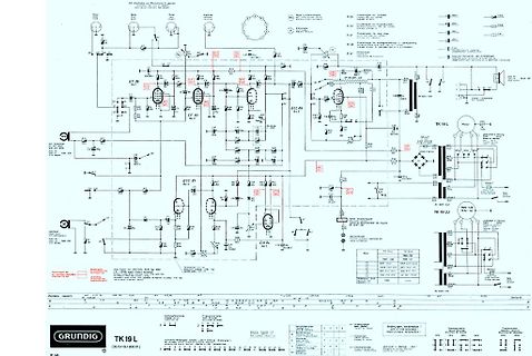
Bild
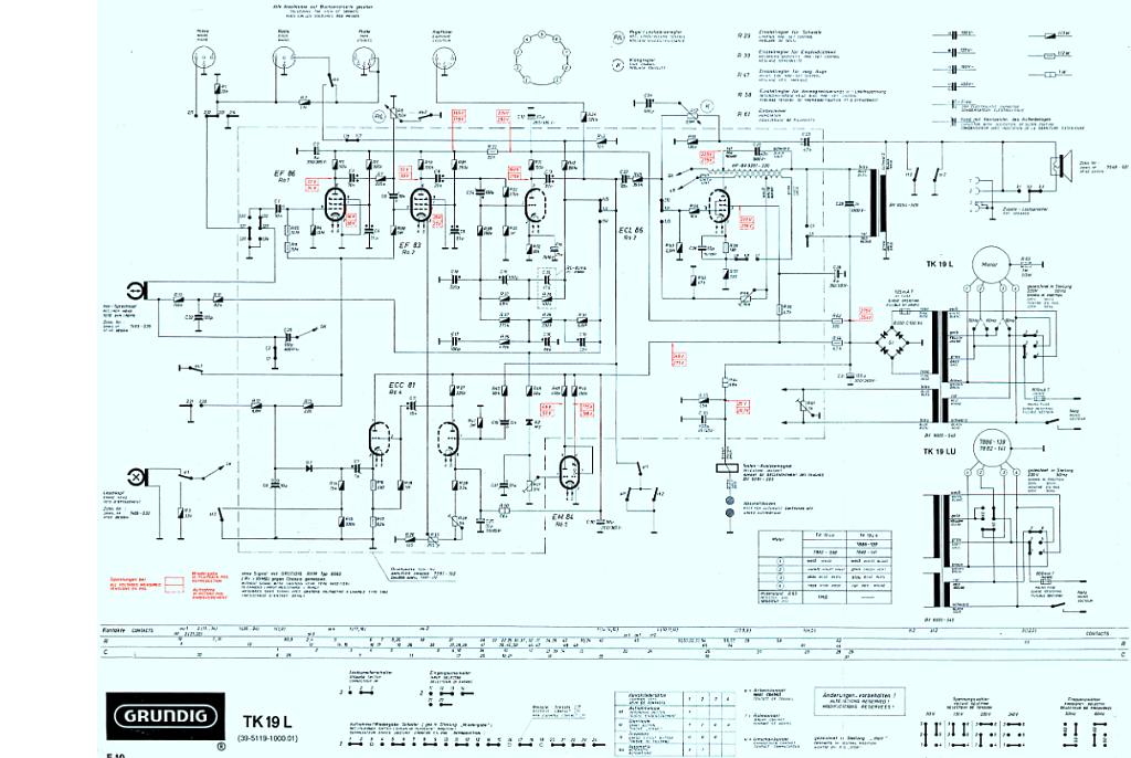
Schaltplan eines Röhrenverstärkers
GRUNDIG TK 19 L EF 86 EF 83 ECL 86 ECC 81 EM 84 TK 19 L TK 19 LU
in „Ich suchen EL95 Ausgangübertrager nieder Leistung?“ · Analoge Elektronik und Schaltungstechnik · · Schaltpläne
-
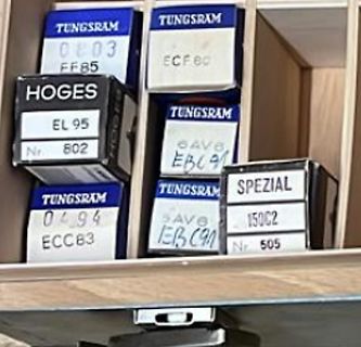
Bild
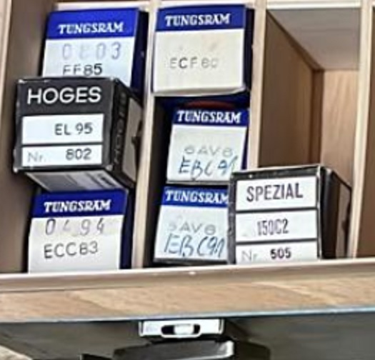
Schachteln mit Elektronenröhren-Typenbezeichnungen
TUNGSRAM 0803 FF85 TUNGSRAM ECF 80 HOGES EL 95 Nr. 802 TUNGSRAM SAV EBC91 TUNGSRAM 0494 ECC83 TUNGSRAM SAV EBC91 SPEZIAL 150C2 Nr. 505
in „Preisfindung für Röhrensortiment“ · Markt · · Fotos
-
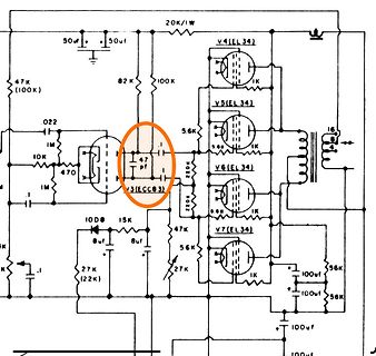
Bild
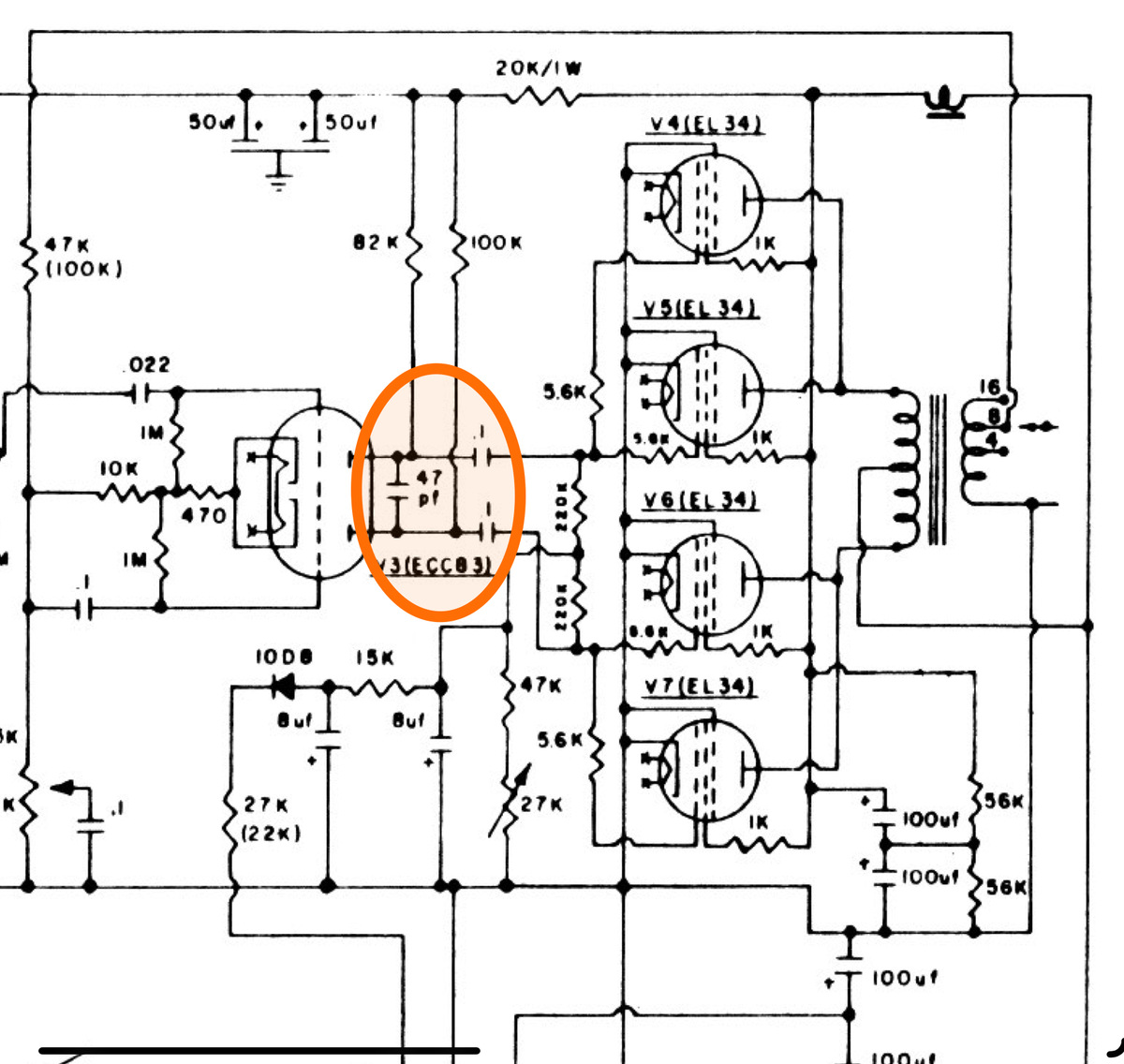
Schaltplan einer Röhrenverstärker-Endstufe
20K/1W, 50uf, 50uf, V4(EL34), 82K, 100K, 1K, 47K (100K), .022, 1M, 10K, 470, V3(ECC83), 47pf, 5.6K, 5.6K, 1K, V5(EL34), V6(EL34), 220K, 220K, 1K, V7(EL34), 10D8, 15K, 8uf, 8uf, 47K, 56K, 27K, 27K (22K), 56K, 100uf, 100uf, 100uf, 100uf
in „STRAMP 2100A“ · Analoge Elektronik und Schaltungstechnik · · Schaltpläne
-
Datei
ioat91sam7se512.h
register AT91_REG ECC_VR; // ECC Version register } AT91S_ECC, *AT91PS_ECC; // -------- ECC_CR : (ECC Offset: 0x0) ECC reset register -------- #define AT91C_ECC_RST ((unsigned int) 0x1 << 0) // (ECC) ECC reset parity //
in „AT91SAM7SE512 Einstieg“ · Mikrocontroller und Digitale Elektronik ·
-
Bild
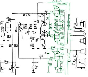
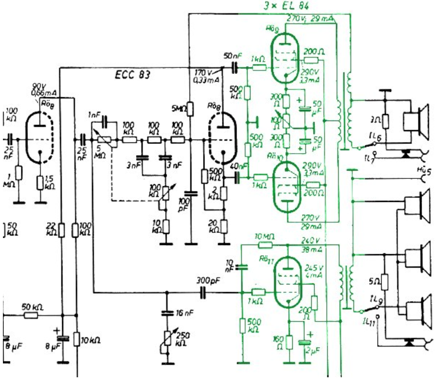
Röhrenverstärker Schaltplan
EL 84, 270V, 29mA, 200 Ohm, 300V, 23mA, 50 uF, 3 Ohm, 1L6, 1L7, EL84, 290V, 23mA, 200 Ohm, 50 uF, ECC 83, 170V, 0.33mA, 500 Ohm, 1k, 5M, 100k, 25nF, 1.5M, 1k, 50k, 8 uF, 10k, 10k, 100nF, 300pF, 250k, 16nF, 10k, 20k, 3nF, 3nF, 5nF, 100k, 100pF, 500 Ohm, 500 Ohm, 40nF, 245V, 38mA, 10M, 1k, 245V, 4mA,
in „EL 84 Simulation - Spannungsüberhöhung“ · Analoge Elektronik und Schaltungstechnik · · Schaltpläne
-
PDF
Rhode_Schwarz_uri_bn1050_handbuch.pdf
Sonstige Daten des Meßgerätes Netzanschluß 110/125/150/220 V, 40... 60 Hz (l 8 W) Bestückung l Röhre ECC 4 0 l Röhre EB 41 l Stabilisator STV 100/60 Z II l Schmelzeinsatz 0 ,4 DIN 41571 (0,4A ;50x20m m ) l Zwergglimmlampe 220V Abmessungen 315 x 227 x 226 mm (R&S-Normkasten Größe 35) Gewicht 10kg i e c
-
Datei
12AX7A.INC
---------------------------------------- * * This model is valid for the following tubes: * 12AX7A/ECC83, 7025, 6EU7, 6681, 6AV6, 12DW7/7247 (Unit #1); * at the following conditions: * Plate voltage : 25..400V * Grid voltage : 0..-3.5V * Cathode current: 0..8mA * * * Connections: Plate * | Grid * | |
in „ECC83 einbinden“ · Analoge Elektronik und Schaltungstechnik ·
-
PDF
R2_MMC1.pdf
. including a powerful error correction code This is similar to using retries on a disk drive but (ECC). is much more sophisticated. The last line of defense is to employ a powerful ECC to correct the 4. Power management for low power operation. data. If ECC is used to recover data, defective bits are
in „Multi Media Card (MMC)“ · Mikrocontroller und Digitale Elektronik ·
-
PDF
R2_MMC1.pdf
. including a powerful error correction code This is similar to using retries on a disk drive but (ECC). is much more sophisticated. The last line of defense is to employ a powerful ECC to correct the 4. Power management for low power operation. data. If ECC is used to recover data, defective bits are
in „(ANSI-)C-Code für MMC-Kommunikation?“ · Mikrocontroller und Digitale Elektronik ·
-
PDF
r2_mmc1.pdf
. including a powerful error correction code This is similar to using retries on a disk drive but (ECC). is much more sophisticated. The last line of defense is to employ a powerful ECC to correct the 4. Power management for low power operation. data. If ECC is used to recover data, defective bits are
in „suche infos über Multimediacard“ · Mikrocontroller und Digitale Elektronik ·
-
Datei
memory.vhd
ram : ram_type := ( 0 => x"a0f0a2cb", 1 => x"10b6fc48", 2 => x"265013b3", 3 => x"819fbeb4", 4 => x"83bbb16f", 5 => x"08f7ff29", 6 => x"e3ca931f", 7 => x"979b3150", 8 => x"cfc216c5", 9 => x"6d189c50", 10 => x"ae791c58", 11 => x"2cc3d8d1", 12 => x"56599273", 13 => x"e4103533", 14 => x"e05c4a1c", 15 =>
-
PDF
1_AMD_BKDG_Family__15h_Mod_00h-0Fh_BKDG.pdf
x8 ECC The use of x8 ECC is indicated in D18F3x180[EccSymbolSize]. The syndrome field uniquely identifies the failing bit positions of a correctable ECC error. Only syndromes identified in Table 130 are correctable
-
PDF
el84se_12ax7_reva.pdf
.02uF/450V OT1 i 400VCT @ 50mA & 6.3VAC @ 1.1A (EDCOR XPWR177 OR SIMILAR) C4 4700pF/450V V1 d 12AX7/ECC83NGLE ENDED (EDCOR GXSE10-8-5k OR SIMILAR) C5 10uF/25V V2 EL84 C6 10uF/400V F1u FUSE, 1A D1,D28 1N400700V Con1 IEC POWER ENTRY/LINE FILTER R1 47k A Con2 1/4" PHONO RECEPTACLE R2, R16* 1M . R3, R4 100k
in „Kennzeichnung Widerstand CC“ · Analoge Elektronik und Schaltungstechnik ·
-
Datei
Info-Images.txt
--------------------------------------------- FlashReader V1.0.2.1, built Sep 4 2006 22:24:11 with ECC Bootscript version 0x00130001 Hynix, 8bit, 64MB U-Boot 2008.10-very-dirty (Jun 19 2011 - 16:21:27) NAND Adress is: 0xb0000000 NAND ID: 0x000076ad Prepare USB DRAM: 128 MB Using default environment I2C
in „Pollin - Receiver-Mainboard mit Twin DVB-[T,C] Tuner, NXP PNX8950EH“ · Mikrocontroller und Digitale Elektronik ·
-
PDF
hitachi_hb28b128mm2.pdf
is set to ‘1’, meaning group write protection is enabled. 18 HB28E016/D032/D064/B128MM2 • DEFAULT_ECC Set by the card manufacturer and defines the ECC codewhichisrecommendedtouse(e.g.thedeviceistested for). The value is set to ‘0’, indicating that no designated ECC is recommended. • R2W_FACTOR Defines

in „0x40 und 0x95 in SD/MMC-Karte“ · Mikrocontroller und Digitale Elektronik ·
-
PDF
hitachi_hb28b128mm2.pdf
is set to ‘1’, meaning group write protection is enabled. 18 HB28E016/D032/D064/B128MM2 • DEFAULT_ECC Set by the card manufacturer and defines the ECC codewhichisrecommendedtouse(e.g.thedeviceistested for). The value is set to ‘0’, indicating that no designated ECC is recommended. • R2W_FACTOR Defines
in „MMC oder SD card connector zum 8515“ · Projekte & Code ·
-
PDF
hitachi_hb28b128mm2.pdf
is set to ‘1’, meaning group write protection is enabled. 18 HB28E016/D032/D064/B128MM2 • DEFAULT_ECC Set by the card manufacturer and defines the ECC codewhichisrecommendedtouse(e.g.thedeviceistested for). The value is set to ‘0’, indicating that no designated ECC is recommended. • R2W_FACTOR Defines
in „MMC/SD SPI Mode Multi Block Write“ · Mikrocontroller und Digitale Elektronik ·
-
PDF
emmc.pdf
WP_GRP_SIZE 5 R [36:32] 1Fh Write protect group enable WP_GRP_ENABLE 1 R [31] 1h Manufacturer default ECC DEFAULT_ECC 2 R [30:29] 0h Write-speed factor R2W_FACTOR 3 R [28:26] 3h Maximum write data block length WRITE_BL_LEN 4 R [25:22] 9h Partial blocks for writes supportWRITE_BL_PARTIAL 1 R [21] 0h Reserved
in „Pin-Swap/Cross IC?“ · Mikrocontroller und Digitale Elektronik ·