-
 Bild
Bild
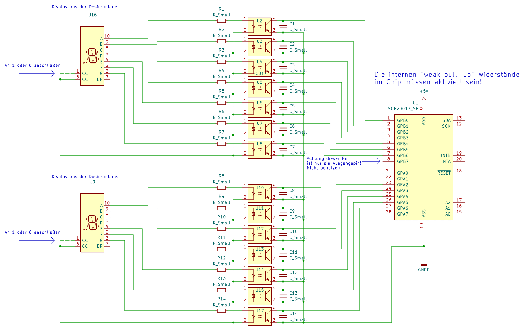
Schaltplan mit MCP23017 und 7-Segment-Anzeigen
Display aus der Dosieranlage. U9 Die internen "weak pull-up" Widerstände im Chip müssen aktiviert sein! MCP23017_SP GPB0 bis GPB7, GPA0 bis GPA7, SDA, SCK, VDD, VSS, RESET, INTB, INT A, A0, A1, A2
in „7 Segment Anzeige auslesen / MCP23017“ · Mikrocontroller und Digitale Elektronik · · Schaltpläne
-
 Bild
Bild
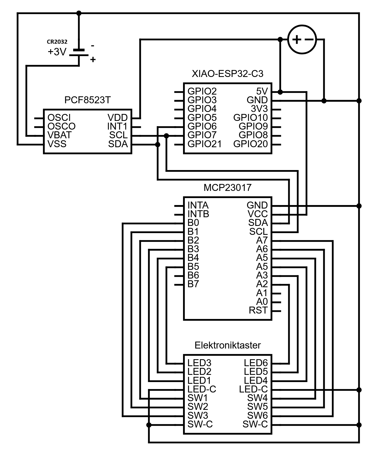
Schaltplan mit XIAO-ESP32-C3, PCF8523T und MCP23017
3V3 GPIO5 GPIO10 GPIO6 GPIO9 GPIO7 GPIO8 GPIO21 GPIO20 PCF8523T OSCI VDD OSCO INT1 VBAT SCL VSS SDA MCP23017 INTA GND INTB VCC B0 SDA B1 SCL B2 A7 B3 A6 B4 A5 B5 A3 B6 A2 B7 A1 A0 RST Elektroniktaster LED3 bis LED6 LED-C SW1 bis SW6 SW-C
in „Elektroniktaster an ESP32“ · Mikrocontroller und Digitale Elektronik · · Schaltpläne
-
Datei
mcp23017_2.c
" //für DG14032 //#define MCP23017_adress1 0x24 //MCP23017 0100 100 nur A2 an high #define MCP23017_adress1 0x48 //MCP23017 0010 010 nur A2 an high //#define MCP23017_adress2 0x25 //MCP23017 0100 101 A2 und A0 an high #define MCP23017
in „I2C - Pull Up Widerstände“ · Mikrocontroller und Digitale Elektronik ·
-
Datei
LiquidTWI2.h
define MCP23017_IPOLA 0x02 #define MCP23017_GPINTENA 0x04 #define MCP23017_DEFVALA 0x06 #define MCP23017_INTCONA 0x08 #define MCP23017_IOCONA 0x0A #define MCP23017_GPPUA 0x0C #define MCP23017_INTFA 0x0E #define MCP23017_INTCAPA 0x10 #define MCP23017_GPIOA 0x12 #define MCP23017_OLATA 0x14 #define MCP23017_IODIRB 0x01 #define MCP23017_IPOLB 0x03 #define MCP23017_GPINTENB 0x05 #define MCP23017_DEFVALB 0x07 #define
in „LCD STN 320x240 große Schrift 16x24 / 20x10 ATmega8 Assembler TWI USART inkl. Fontgenerator VBA“ · Projekte & Code ·
-
Datei
channel.h
MCP23017_GPPUA 0x0C #define MCP23017_INTFA 0x0E #define MCP23017_INTCAPA 0x10 #define MCP23017_GPIOA 0x12 #define MCP23017_OLATA 0x14 #define MCP23017_IODIRB 0x01 #define MCP23017_IPOLB 0x03 #define MCP23017_GPINTENB 0x05 #define MCP23017_DEFVALB 0x07 #define MCP23017_INTCONB 0x09 #define MCP23017_IOCONB 0x0B #define MCP23017_GPPUB 0x0D #define MCP23017_INTFB 0x0F #define MCP23017_INTCAPB 0x11 #define MCP23017_GPIOB 0x13 #define
in „ATtiny85 und MCP23017 liefert NACK“ · Mikrocontroller und Digitale Elektronik ·
-
PDF
MCP2307_IO_Expansion_Board_User_Manual_EN.pdf
MCP23017 IO Expansion Board MCP23017 IO Expansion Board User Manual OVERVIEW This is an I/O expansion module uses I2C interface, gives you 16 GPIO. Supports using 8 expansion modules at the same for up
in „kennt jemand sich aus mit MC23017 IO-Board“ · Mikrocontroller und Digitale Elektronik ·
-
PDF
MCP23017-Datasheet.pdf
interrupt-on-change and/or internal weak pull-up resistor. V 5 9 P Power DD VSS 6 10 P Ground NC/CS 7 11 I NC (MCP23017)/Chip Select (MCP23S17) SCK 8 12 I Serial clock input SDA/SI 9 13 I/O Serial data I/O (MCP23017)/Serial data input (MCP23S17) NC/SO 10 14 O NC (MCP23017)/Serial data out (MCP23S17) A0 11 15 I Hardware
in „kennt jemand sich aus mit MC23017 IO-Board“ · Mikrocontroller und Digitale Elektronik ·
-
Datei
kklcdxx.c
use_twilcd72 //uint8_t mcp23017_72_A,mcp23017_72_B; //lcdbyte d7-d6-d5-d4-en-rs-//-// mcp23017_72_A= (mcp23017_72_A & 0b00000011) + (lcdbyte & 0b11111100); //mcp23017_72_B= (mcp23017_72_B & 0b00111111) + (((lcdbyte & 0b00000100)<<5)); set_mcp23017_outAB(mcp23017_72_A, mcp23017_72_B); set_mcp23017_outAB((mcp23017_72_A + WERTpinE), mcp23017_72_B ); set_mcp23017_outAB(mcp23017_72_A, mcp23017_72_B); #endif #if use_twilcd72x set_mcp23017_outAB
in „I2C LCD mit Raspberry“ · Mikrocontroller und Digitale Elektronik ·
-
Datei
kklcdxx.c
use_twilcd72 //uint8_t mcp23017_72_A,mcp23017_72_B; //lcdbyte d7-d6-d5-d4-en-rs-//-// mcp23017_72_A= (mcp23017_72_A & 0b00000011) + (lcdbyte & 0b11111100); //mcp23017_72_B= (mcp23017_72_B & 0b00111111) + (((lcdbyte & 0b00000100)<<5)); set_mcp23017_outAB(mcp23017_72_A, mcp23017_72_B); set_mcp23017_outAB((mcp23017_72_A + WERTpinE), mcp23017_72_B ); set_mcp23017_outAB(mcp23017_72_A, mcp23017_72_B); #endif #if use_twilcd72x set_mcp23017_outAB
in „Verzweiflung um LCD Lib von Peter Fleury“ · Mikrocontroller und Digitale Elektronik ·
-
Datei
Programm.txt
begin // ############################################################################# // I2C lesen MCP23017 Soft_I2C_Start(); // Issue start signal Soft_I2C_Write(0x40); // Adresse MCP23017 schreiben ==> Soft_I2C_Write(GPIOB); // Adresse auf GPIOB setzen Soft_I2C_Write(0x41); // Addrese MCP23017 lesen
in „ATMega32 liest über I2C-Bus die Eingänge vom MCP23017“ · Mikrocontroller und Digitale Elektronik ·
-
Datei
Programm.txt
begin // ############################################################################# // I2C lesen MCP23017 Soft_I2C_Start(); // Issue start signal Soft_I2C_Write(0x40); // Adresse MCP23017 schreiben ==> Soft_I2C_Write(GPIOB); // Adresse auf GPIOB setzen Soft_I2C_Write(0x41); // Addrese MCP23017 lesen
in „ATMega32 liest über I2C-Bus die Eingänge vom MCP23017“ · Mikrocontroller und Digitale Elektronik ·
-
Datei
MCP23017_LIB.c
// (!) } void mcp23017_clear_all_outputs(uint8_t i2c_address) { mcp23017_write_gpio_a(i2c_address, 0x00); mcp23017_write_gpio_b(i2c_address, 0x00); } void mcp23017_drive_output(uint8_t i2c_address, uint8_t output_no) //output_no 1..16 { if (output_no <= 8) // I/O BANK_A { mcp23017_write_gpio_b(i2c_address, 0x00); mcp23017_write_gpio_a(i2c_address, 1<<(output_no-1)); } else if (output_no <=16) // I/O BANK_B { output_no -= 9; mcp23017_write_gpio_a(i2c_address, 0x00); mcp23017
in „MCP23017 funktioniert erst wie er soll nach Reset des µC“ · Mikrocontroller und Digitale Elektronik ·
-
Datei
Adafruit_CharLCDPlate.py
------------------------------------------------------------ # Constants # Port expander registers MCP23017_IOCON_BANK0 = 0x0A # IOCON when Bank 0 active MCP23017_IOCON_BANK1 = 0x15 # IOCON when Bank 1 active # These are register addresses when in Bank 1 only: MCP23017_GPIOA = 0x09 MCP23017_IODIRB =
in „ATmega32 - LCD mit Adafruit Breakout - Code portieren“ · Mikrocontroller und Digitale Elektronik ·
-
Datei
channel.c
(0x00); i2c_stop(); // set all to 0 i2c_start(MCP23017_ADR + I2C_WRITE); i2c_write(MCP23017_OLATA); i2c_write(0x00); i2c_stop(); // Port B as output i2c_start(MCP23017_ADR + I2C_WRITE); i2c_write(MCP23017_IODIRB); i2c_write(0x00); i2c_stop(); // set all to 0 i2c_start(MCP23017_ADR + I2C_WRITE); i2c_write(MCP23017_OLATB); i2c_write(0x00); i2c_stop(); }
in „ATtiny85 und MCP23017 liefert NACK“ · Mikrocontroller und Digitale Elektronik ·
-
PDF
Rollladensteuerung.pdf
AVR-Controller: 16kB Flash 512 Byte EEPROM 1kB RAM 2 ADC-Kanäle TWI 1 Eingang Wandschalter MCP23017-Interrupt (nicht zwingend interruptfähig) 1 Eingang Keypad MCP23017-Interrupt (nicht zwingend interruptfähig) 1 Eingang HMI Erkennung (nicht zwingend interruptfähig) 1 flankengetriggerter
-
Datei
Loesung.txt
Soft_I2C_Write(0x41); // Addrese MCP23017 lesen ==> PortF := Soft_I2C_Read(0); // Lesen der Eingänge des MCP23017 Soft_I2C_Stop(); // Issue stop signal delay_ms(500); Soft_I2C_Start(); // Issue start signal Soft_I2C_Write(0x40); // Adresse MCP23017 schreiben ==> Soft_I2C_Write(OLATA); // Adresse auf GPIOB setzen Soft_I2C_Write(PortF); // gelesene Daten von PortB des MCP23017 an PortA des MCP23017 ausgeben Soft_I2C_Stop(); // Issue stop signal
in „ATMega32 liest über I2C-Bus die Eingänge vom MCP23017“ · Mikrocontroller und Digitale Elektronik ·
-
PDF
Rollladensteuerung.pdf
AVR-Controller: 16kB Flash 512 Byte EEPROM 1kB RAM 8 ADC-Kanäle TWI 1 Eingang Wandschalter MCP23017-Interrupt (nicht zwingend interruptfähig) 1 Eingang Keypad MCP23017-Interrupt (nicht zwingend interruptfähig) 1 Eingang HMI Erkennung (nicht zwingend interruptfähig) 1 flankengetriggerter
-
PDF
Rollladensteuerung.pdf
AVR-Controller: 16kB Flash 512 Byte EEPROM 1kB RAM 8 ADC-Kanäle TWI 1 Eingang Wandschalter MCP23017-Interrupt (nicht zwingend interruptfähig) 1 Eingang Keypad MCP23017-Interrupt (nicht zwingend interruptfähig) 1 Eingang HMI Erkennung (nicht zwingend interruptfähig) 1 flankengetriggerter
-
PDF
Rollladensteuerung.pdf
AVR-Controller: 16kB Flash 512 Byte EEPROM 1kB RAM 8 ADC-Kanäle TWI 1 Eingang Wandschalter MCP23017-Interrupt (nicht zwingend interruptfähig) 1 Eingang Keypad MCP23017-Interrupt (nicht zwingend interruptfähig) 1 Eingang HMI Erkennung (nicht zwingend interruptfähig) 1 flankengetriggerter
-
Datei
MCP23017.h
/* * MCP23017.h * * Created: 02.02.2015 19:06:45 * Author: Stephan */ #ifndef MCP23017_H_ #define MCP23017_H_ #define IODIRA 0x00 #define IODIRB 0x01 #define IOPOLA 0x02 #define IOPOLB 0x03 #define GPINTENA
in „Probleme beim auslesen des MCP23017“ · Mikrocontroller und Digitale Elektronik ·
-
Datei
functions.c
ZIMbedarfCtrl=ZIMbedarf; //wait10; for(i=3;i<6;i++) { if(!gbi(ZimAbwesend,i)){maskeZIM[i]='x';}} //mcp23017_72_B= (mcp23017_72_B & 0b11000000) + (ZIMbedarf & 0b00111111); //if(mcp23017gefunden==0){set_mcp23017_out(72,0x13,mcp23017_72_B);} } } #ifndef LaufzeitH volatile u8 LaufzeitH; #endif void lcd_anzeige
in „Heizungssteuerung Wärmepumpe Fußbodenheizung“ · Mikrocontroller und Digitale Elektronik ·
-
Datei
main.c
#define F_CPU 8000000UL #include <avr/io.h> #include "MCP23017_LIB.h" #include <util/delay.h> int main(void) { _delay_ms(500); mcp23017_init(0x4e); while (1) { for (int i=1; i<=16; i++) { mcp23017_drive_output(0x4e, i); _delay_ms(20); } mcp23017_clear_all_outputs
in „MCP23017 funktioniert erst wie er soll nach Reset des µC“ · Mikrocontroller und Digitale Elektronik ·
-
Datei
MCP23017.c
/* * MCP23017.c * * Created: 04.02.2015 19:12:51 * Author: Stephan */ #include <stdint.h> #include "TWI_Master.h" #include "MCP23017.h" uint8_t MCP23017_readByte(uint8_t SlaveAddress,uint8_t RegisterAddress)
in „Probleme beim auslesen des MCP23017“ · Mikrocontroller und Digitale Elektronik ·
-
Datei
lcd_routines.h
und die 4 // Datenleitungen müssen auf aufeinanderfolgenden Pins liegen //Adresse des Slave Devices MCP23017 //Die ersten 4 Bit sind laut Datenblatt definiert(0100) //Die letzten 3 Bit werden über die Pins A0-A2 definiert #define SLAVE 0b0100000 // LCD DB4-DB7 <--> PORTB an MCP23017 Bit GPB1-GPB4 #define LCD_PORT 0x13 //GPIOB Register Addresse des MCP23017 #define LCD_DDR 0x01 // IODIRB Register addresse des MCP23017 #define LCD_DB 1 // GPB1 // LCD RS <--> PORTD Bit PD4 (RS: 1=Data, 0=Command) #define LCD_RS 7 // LCD EN <--> PORTD Bit PD5 (EN: 1-
in „LCD ansteuerung mit einem ATMega16 und I2C“ · Mikrocontroller und Digitale Elektronik ·
-
Datei
lcd-routines.h
und die 4 // Datenleitungen müssen auf aufeinanderfolgenden Pins liegen //Adresse des Slave Devices MCP23017 //Die ersten 4 Bit sind laut Datenblatt definiert(0100) //Die letzten 3 Bit werden über die Pins A0-A2 definiert #define SLAVE 0b0100000 // LCD DB4-DB7 <--> PORTB an MCP23017 Bit GPB1-GPB4 #define LCD_PORT 0x13 //GPIOB Register Addresse des MCP23017 #define LCD_DDR 0x01 // IODIRB Register addresse des MCP23017 #define LCD_DB 1 // GPB1 // LCD RS <--> PORTD Bit PD4 (RS: 1=Data, 0=Command) #define LCD_RS 7 // LCD EN <--> PORTD Bit PD5 (EN: 1-
in „LCD ansteuerung mit einem ATMega16 und I2C“ · Mikrocontroller und Digitale Elektronik ·
-
Datei
lcd-routines.h
und die 4 // Datenleitungen müssen auf aufeinanderfolgenden Pins liegen //Adresse des Slave Devices MCP23017 //Die ersten 4 Bit sind laut Datenblatt definiert(0100) //Die letzten 3 Bit werden über die Pins A0-A2 definiert #define SLAVE 0b0100000 // LCD DB4-DB7 <--> PORTB an MCP23017 Bit GPB1-GPB4 #define LCD_PORT 0x13 //GPIOB Register Addresse des MCP23017 #define LCD_DDR 0x01 // IODIRB Register addresse des MCP23017 #define LCD_DB 1 // GPB1 // LCD RS <--> PORTB BIT GPIOB7 (RS: 1=Data, 0=Command) #define LCD_RS 7 // LCD EN <--> PORTB BIT GPIOB5 (
in „LCD ansteuerung mit einem ATMega16 und I2C“ · Mikrocontroller und Digitale Elektronik ·
-
Datei
Functions.ino
EEPROM.write(address+2, u.b[2]); EEPROM.write(address+3, u.b[3]); } //THESE FUNCTIONS WILL TURN THE PINS OF A MCP23017 ON AND OFF. THIS ALLOWS FOR THE CONTROL OF UP TO 16 MACHINES. //EVEN MORE MACHINES COULD BE CONTROLLED BY ADDING MORE MCP23017s, BUT THIS CODE WOULD HAVE TO BE MODIFIED. void turnMCP23017PinOn(
in „Heliostatensteuerung mit Arduino Uno“ · Mikrocontroller und Digitale Elektronik ·
-
Datei
MCP23017.h
#ifndef mcp23017_H_ #define mcp23017_H_ #define I2C_Slave_Adresse 0x40 #define I2C_Slave_Lesen 1 #define I2C_Slave_Schreiben 0 #define IODIRA 0x00 #define IODIRB 0x01 #define IPOLA 0x02 #define IPOLB 0x03 #define
in „I2C - Pull Up Widerstände“ · Mikrocontroller und Digitale Elektronik ·
-
Datei
FlipDot.ino
** ********************************************************/ #include <Wire.h> #include "Adafruit_MCP23017.h" Adafruit_MCP23017 mcp; // die Zeichenkodierung uint8_t hex2dot[][5] = { {0x7, 0x5, 0x5, 0x5, 0x7}, // 0 {0x2, 0x2, 0x2, 0x2, 0x2}, // 1 {0x7, 0x1, 0x7, 0x4, 0x7}, // 2 {0x7, 0x1, 0x3, 0x1, 0x7
in „Flipdot Display Projekt (Hilfe Logik Erbeten)“ · Mikrocontroller und Digitale Elektronik ·
-
Datei
FlipDot.ino
** ********************************************************/ #include <Wire.h> #include "Adafruit_MCP23017.h" Adafruit_MCP23017 mcp; // die Zeichenkodierung uint8_t hex2dot[][5] = { {0x7, 0x5, 0x5, 0x5, 0x7}, // 0 {0x2, 0x2, 0x2, 0x2, 0x2}, // 1 {0x7, 0x1, 0x7, 0x4, 0x7}, // 2 {0x7, 0x1, 0x3, 0x1, 0x7
in „Flipdot Display Projekt (Hilfe Logik Erbeten)“ · Mikrocontroller und Digitale Elektronik ·
-
Datei
FlipDot_02.ino
** ********************************************************/ #include <Wire.h> #include "Adafruit_MCP23017.h" Adafruit_MCP23017 mcp; // die Zeichenkodierung uint8_t hex2dot[][5] = { {0x7, 0x5, 0x5, 0x5, 0x7}, // 0 {0x2, 0x2, 0x2, 0x2, 0x2}, // 1 {0x7, 0x1, 0x7, 0x4, 0x7}, // 2 {0x7, 0x1, 0x3, 0x1, 0x7
in „Flipdot Display Projekt (Hilfe Logik Erbeten)“ · Mikrocontroller und Digitale Elektronik ·
-
Datei
mcp_flipdot_v3.ino
** ********************************************************/ #include <Wire.h> #include "Adafruit_MCP23017.h" Adafruit_MCP23017 mcp; // die Zeichenkodierung uint8_t hex2dot[][5] = { {0x07, 0x05, 0x05, 0x05, 0x07}, // 0 {0x02, 0x02, 0x02, 0x02, 0x02}, // 1 {0x07, 0x01, 0x07, 0x04, 0x07}, // 2 {0x07,
in „Flipdot Display Projekt (Hilfe Logik Erbeten)“ · Mikrocontroller und Digitale Elektronik ·
-
Datei
mcp_first_test2.ino
** ********************************************************/ #include <Wire.h> #include "Adafruit_MCP23017.h" Adafruit_MCP23017 mcp; // die Zeichenkodierung uint8_t hex2dot[][5] = { {0x7, 0x5, 0x5, 0x5, 0x7}, // 0 {0x2, 0x2, 0x2, 0x2, 0x2}, // 1 {0x7, 0x1, 0x7, 0x4, 0x7}, // 2 {0x7, 0x1, 0x3, 0x1, 0x7
in „Flipdot Display Projekt (Hilfe Logik Erbeten)“ · Mikrocontroller und Digitale Elektronik ·
-
Datei
mcp_flipdot_v3.ino
** ********************************************************/ #include <Wire.h> #include "Adafruit_MCP23017.h" Adafruit_MCP23017 mcp; // die Zeichenkodierung uint8_t hex2dot[][5] = { {0x07, 0x05, 0x05, 0x05, 0x07}, // 0 {0x02, 0x02, 0x02, 0x02, 0x02}, // 1 {0x07, 0x01, 0x07, 0x04, 0x07}, // 2 {0x07,
in „Flipdot Display Projekt (Hilfe Logik Erbeten)“ · Mikrocontroller und Digitale Elektronik ·
-
Datei
FlipDot_V04.ino
** ********************************************************/ #include <Wire.h> #include "Adafruit_MCP23017.h" Adafruit_MCP23017 mcp; // die Zeichenkodierung uint8_t hex2dot[][5] = { {0x07, 0x05, 0x05, 0x05, 0x07}, // 0 {0x02, 0x02, 0x02, 0x02, 0x02}, // 1 {0x07, 0x01, 0x07, 0x04, 0x07}, // 2 {0x07,
in „Flipdot Display Projekt (Hilfe Logik Erbeten)“ · Mikrocontroller und Digitale Elektronik ·
-
Datei
MCP23017.asm
;HardwareAdressEnable 1=Aktiviert AdressPins 0=Deaktiviert AdressPins ( Nicht für MCP23017 ) #define MCP_DISSLW 0 ;SlewRateControl 1=Langsame geschwindigkeit aus 0=Langsame Geschwindigkeit an #define MCP_SEQOP 0 ;Sequentielle Operations Mode 1=AdressPointer geht nicht von allein weiter
in „MCP23017 Assembler Initialisierung“ · Mikrocontroller und Digitale Elektronik ·
-
PDF
flipdot_neu_Register.pdf
Oben 74HC138D SET Ziffer SET Ziffer 7 Y7 G2B 5 D Ziffer 6 9 Y6 G2A 4 N 10 6 G 11 Y5 G1 Enable PortA7 MCP23017 Flipdot Display 12 Y4 13 Y3 3 Y2 C 14 Y1 B 2 6 Ziffern Ziffer 05 Y0 A 1 r ffi IC2 Z Ziffernauswah 0-6 V a 5x3 Dots 5 + 74HC574D 1 OC 1 74HC221D R 4075D 13 11 15 10 12 CLK 4 R/C 14 11 12 9 Q C C1 8Q
in „Flipdot Display Projekt (Hilfe Logik Erbeten)“ · Mikrocontroller und Digitale Elektronik ·
-
Datei
MCP23017.PAS
{ *** *** Exerciser for I2C GPIO chip MCP23017 *** *** Martin Hepperle, 2018 *** } Program MCP23017; Const I2C_BASE = $60; _IODIRA = $00; _IODIRB = $01; _IPOLA = $02; _IPOLB = $03; _GPPUA = $0C; _GPPUB = $0D; _GPIOA = $12; _GPIOB = $13; _OLATA
in „CP/M auf ATmega88“ · Mikrocontroller und Digitale Elektronik ·
-
Datei
mcp_flipdot_hc05.ino
** ********************************************************/ #include <Wire.h> #include "Adafruit_MCP23017.h" Adafruit_MCP23017 mcp; // die Zeichenkodierung uint8_t hex2dot[][5] = { {0x07, 0x05, 0x05, 0x05, 0x07}, // 0 {0x01, 0x01, 0x01, 0x01, 0x01}, // 1 {0x07, 0x01, 0x07, 0x04, 0x07}, // 2 {0x07,
in „Flipdot Display Projekt (Hilfe Logik Erbeten)“ · Mikrocontroller und Digitale Elektronik ·
-
Datei
mcp_flipdot_v5.ino
** ********************************************************/ #include <Wire.h> #include "Adafruit_MCP23017.h" Adafruit_MCP23017 mcp; // die Zeichenkodierung uint8_t hex2dot[][5] = { {0x07, 0x05, 0x05, 0x05, 0x07}, // 0 {0x02, 0x02, 0x02, 0x02, 0x02}, // 1 {0x07, 0x01, 0x07, 0x04, 0x07}, // 2 {0x07,
in „Flipdot Display Projekt (Hilfe Logik Erbeten)“ · Mikrocontroller und Digitale Elektronik ·
-
PDF
SNET-System.pdf
Reserve Rolladen Motoren SNET-Relais_32 CAN-Controller r r r r r c k k c c Arduino Nano C t C t C t C t MCP23017 C t I S I S MCP23017 I S I S I S 2 x x 2 2 2 2 DC/DC Step Down SNET1 SNET2 2x3 Stecker 2x3 Stecker 24V ETH Reserve L2 SNET-MQTT-Gateway Rolladen Motoren CAN-Controller W P CAT 5 (ohne Schirm) Arduino
in „Auf der Zielgeraden gescheitert (MCP23017 mit Relaiskarte instabil)“ · Mikrocontroller und Digitale Elektronik ·
-
PDF
MCP23017-IO-Expansion-Board-Schematic.pdf
PIU1012 RESET PIU1017A2 VCPIH201 1 SDAD PIU1013L A2PIU1016A1 1 Header 10 PIU10NCA A0PIU1015A0 Header 10 MCP23017 VCC VCC B P2O1 VCC P0 B R2R P100nF 1CR1 RESETP110K 100K P0O2 GND L1 P100nF PWR LED GND VCC L2 R2 P42 VCC VCC VCC H3H R3R R4R H4H GND PIH301C 10K 10K PIH401C 1 PIH302D R1 P41 1 PIH402D C 3 PIH303
in „kennt jemand sich aus mit MC23017 IO-Board“ · Mikrocontroller und Digitale Elektronik ·
-
PDF
testboard_05_00.sch.pdf
SDA GPB1 2 GPB2 3 15 A0 GPB3 4 16 A1 GPB4 5 17 A2 GPB5 6 GPB6 7 10 VSS GPB7 8 0 0 0 0 0 2 0 4 0 6 0 MCP23017_1MM 2 5 4 5 6 5 8 5 1 5 1 5 1 5 1 5 GND R 1 R 1 R 1 R 1 R 1 R 1 R 1 R 1 1 2 3 4 5 6 7 8 9 1 1 1 1 1 1 1 VCC Button control D D D D D D D D D D D D D D D D IC2 L L L L L L L L L L L L L L L L 9
in „Zusatzplatine mit 4x4 Leucht-Tastern für Arduino-Neueinsteiger“ · Offtopic ·
-
PDF
Schematic_SIMInterface-Base_Schaltplan_20190313164157.pdf
3x6 123 4 5789 111111 111 +5V A A LED1 LTST-C155KGJRKT C5 +5V R5 100nF 330 U1 +5V ATMEGA32U4-AU U3 MCP23017T-ESS Buttons 1-16 330 42 AREF PF0 (ADC0) 41 J1 R4 PF1 (ADC1) 40 12 SCL GPA0 21 Header_Male_2x16 copy C6 2 UVcc PF4 (ADC4TCK) 39 13 SDA GPA1 22 16 32 1uF +5V PF5 (ADC5TMS)) 38 Connector for GPA2
in „ATMEGA32U4 Schaltplan“ · Mikrocontroller und Digitale Elektronik ·
-
PDF
raffstorecontrol.pdf
SCL 2 1,3 inch OLED 100nF 1 I1 O1 18 1 GND J5 U9 2 17 2 2 3 3 Conn_01x04 GND U8 I2 O2 3.3V 4 PC817 9 MCP23017 3 I3 O3 16 3 1 4 4 15 4 In1 D1 A I4 O4 1 A SDA 13 SDA D GPB0 1 5 I5 O5 14 5 J1 R1 2.2k 2 3 12 V 2 6 13 6 10K R5 GND GND SCL SCK GPB1 I6 O6 SW4 GPB2 3 7 I7 O7 12 7 4 8 N 11 8 hoch GPB3 5 I8 G O8
in „mcp23017 pull up / Vorwiderstand erforderlich?“ · Mikrocontroller und Digitale Elektronik ·
-
PDF
raffstorecontrol.pdf
COM SCL 2 1,3 inch OLED 100nF 1 I1 O1 18 1 GND J5 U9 2 17 2 3 Conn_01x04 GND U8 I2 O2 3.3V 4 PC817 9 MCP23017 3 I3 O3 16 3 1 4 4 15 4 In1 D1 A I4 O4 A SDA 13 SDA D GPB0 1 5 I5 O5 14 5 J1 Q3 2.2k 2 3 12 V 2 6 13 6 IRLML 6402 R5 GND GND SCL SCK GPB1 I6 O6 SW4 GPB2 3 7 I7 O7 12 7 D S 4 8 N 11 8 hoch GPB3
in „mcp23017 pull up / Vorwiderstand erforderlich?“ · Mikrocontroller und Digitale Elektronik ·
-
Datei
mcp.h
#ifndef MCP_H_ #define MCP_H_ #include <avr/io.h> #define MCP_IOCON_BANK 0x00 void mcp_init(uint8_t data); void mcp_write_byte(uint8_t addr, uint8_t reg, uint8_t data); void mcp_write_bit(uint8_t addr, uint8_t
in „Ansteuern eines MCP23017“ · Mikrocontroller und Digitale Elektronik ·
-
PDF
A-4_MCP23017.pdf
.18,0m PA3 PA4 28AWG0,08mm²,15cm NYM-J3x1,5Max.18,0m 28AWG0,08mm²,15cm NYM-J3x1,5Max.18,0m WaveshareMCP23017 PA5 PA6 28AWG0,08mm²,15cm NYM-J3x1,5Max.18,0m PA7 Max.150mA PB0 28AWG0,08mm²,15cm NYM-J3x1,5Max.10,0m 28AWG0,08mm²,15cm NYM-J3x1,5Max.8,0m PB1 28AWG0,08mm²,15cm NYM-J3x1,5Max.8,0m PB2 28AWG0,08mm²,15cm
in „MCP23017 friert ein, stürzt ab“ · Mikrocontroller und Digitale Elektronik ·
-
PDF
RL-Extender.pdf
Draufsicht der Logik-Relaiseinheit 8*Anschluss Wandschalter und Relais Relaisplatine 12V f. Relais MCP23017 Rohrmotor- Anschluß 230V Eingang Anschluss 12V Steckernetzteil 433MHz Empfänger mit Antenne Logikplatine Rollladen-Extender Beschreibung Copyright (c) BBC-Hörer 2016-2018 - 6 - Abbildung 3: Aufbau
-
Datei
SteueruC.asm
erlauben ;; Schnitstellen initialisieren und Peripherie Innitializieren call Init_RS232 call Init_IIC ; MCP initialisieren ; call Înit_MCP ; LCD Initializieren call InitLCD movlw boot call Write ; CGRAM mit eigenen Zeichen beschreiben call SETCGRAM_KARTE ;;;;;;;;;;;;;; Hauptprogramm;;;;;;;;;;;;;;;; Test btfss
in „PIC16f876A UART Puffer“ · Mikrocontroller und Digitale Elektronik ·