-
Bild
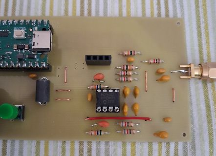
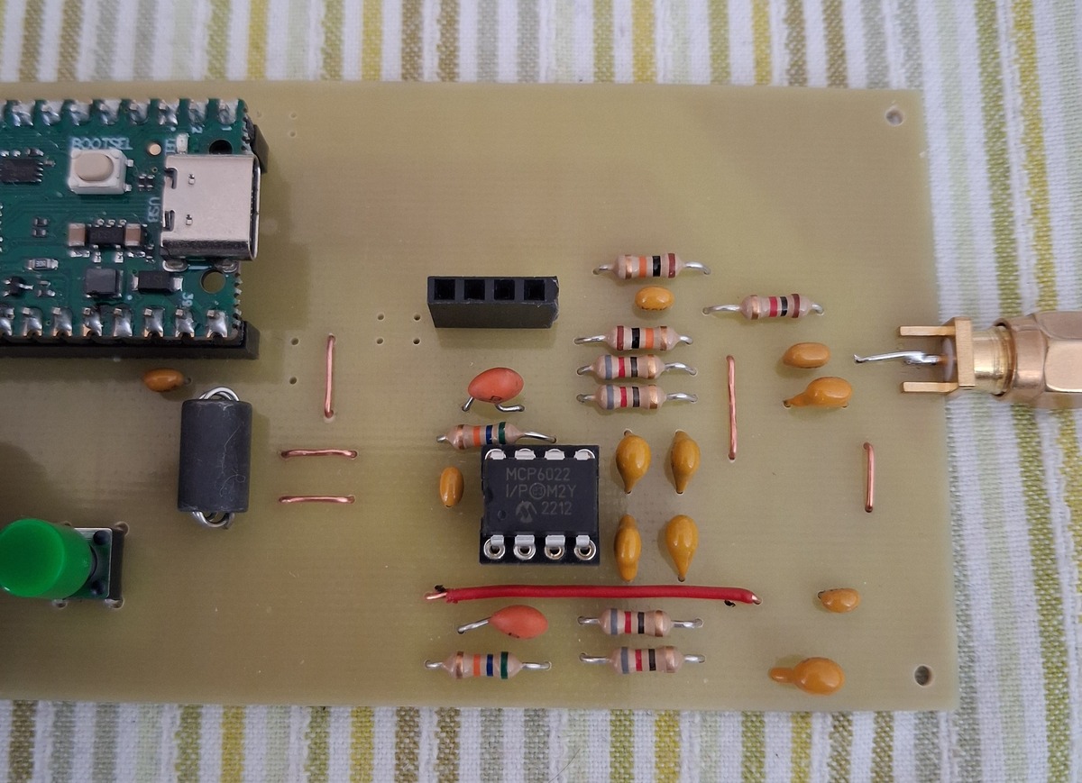
Leiterplatte mit MCP6022 und Bootsel-Modul
BOOTSEL MCP6022 1/P@M2Y 2212
in „Raspberry Pi Pico SDR“ · HF, Funk und Felder · · Platinenfotos
-
Datei
PICO-RX_1_.html
<big> </big></b></a></big><br> <b>[9]</b> <a href="https://www.conrad.de/de/p/microchip-technology-mcp6022-i-p-linear-ic-operationsverstaerker-mehrzweck-pdip-8-651498.html"><big><b>https://www.conrad.de/de/p/microchip-technology-mcp6022-i-p-linear-ic-operationsverstaerker-mehrzweck-pdip-8-651498.htm<
-
PDF
PICO_SDR.sch.pdf
180 VCC 16 L4 33µH C4 10µ R13100 IC2B 7 RX_I 2 1 A C1 220n . P_0 5 +3V3 A B 7 1A 1B1 6 33µH 10µ 100 MCP6022 NF - rechts 2 SJ4 1 RF_1 5 R4 100k C D . b 1B2 4 C27 C26 C12 C11 BIAS 2 SJ3 1 S S A 1B3 10n 10n 10n 10n 0 N C33 220n 1B4 3 C24 27p C 10µ G 2 SJ2 1 N C C D a . r G V S S RF_2 C 9 10 GND GND GND GND
-
PDF
Operationsverstaerker_Auswahl.pdf
meist auch deutlich höhere Bandbreiten haben. Geeignete bzw. passende Typen wären beispielsweise: MCP6022 (Rail-to-Rail, 2,8 MHz, 7 V/µs, allerdings max. 6 V Versorgung → nicht geeignet für ±15 V) OPA197 – passt sehr gut: Versorgung: ±2,25 V bis ±18 V Rail-to-Rail-Ausgang GBW: 10 MHz Slew Rate: 20 V
in „Suchmaschine für Halbleiter gesucht“ · Analoge Elektronik und Schaltungstechnik ·
-
PDF
DE2012010361.pdf
aufReproduzierbarkeitundFunktiongetestet. 36 01-2012 elektor testEn & messen 3V3 R1 L1 CT1 k 1 U1 = MCP6022 10u 10mH J1 J2 1 3 5 8 R2 C1 1 2 1 7 2 U1A U1B 51R 2 6 3 TO ANTENNA 1u 4 entfernt anordnen, wodurch der Empfang deutlich weniger von R4 R3 TO RECEIVER VIA COAX CABLE Störstrahlungen anderer Geräte
-
Bild
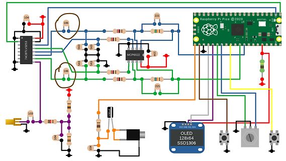
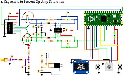
Schaltplan mit Raspberry Pi Pico und OLED Display
74CTLV3253, 104, 106, 563, 563, 563, 221, MCP6022, 104, 221, Raspberry Pi Pico © 2020, BOOTSEL, 106, 103, 104, 100uF, OLED 128x64 SSD1306, VCC GND SCL SDA
in „Raspberry Pi Pico SDR“ · HF, Funk und Felder · · Schaltpläne
-
Bild
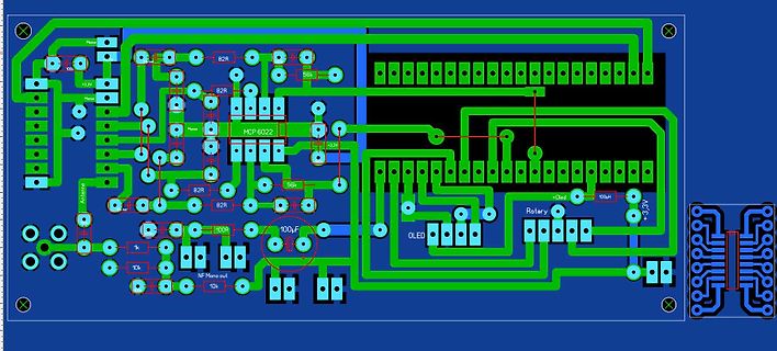
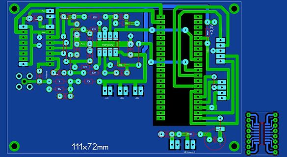
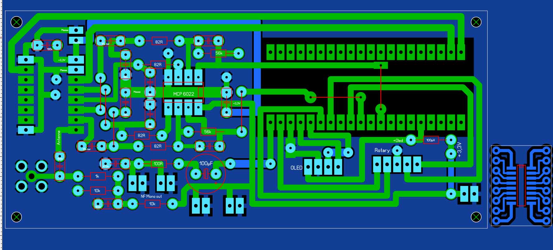
PCB-Layout einer elektronischen Schaltung
Masse +3,3V 82R 56k MCP 6022 82R 82R Antenne 10k 100R 100uF NF Mono out 10k OLED Rotary +OLED 100uH -3,3V
in „Raspberry Pi Pico SDR“ · HF, Funk und Felder · · Layouts
-
Bild
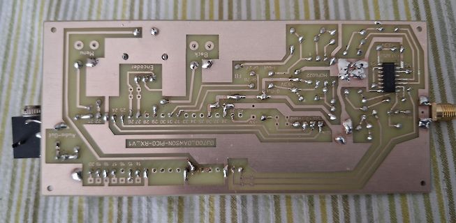
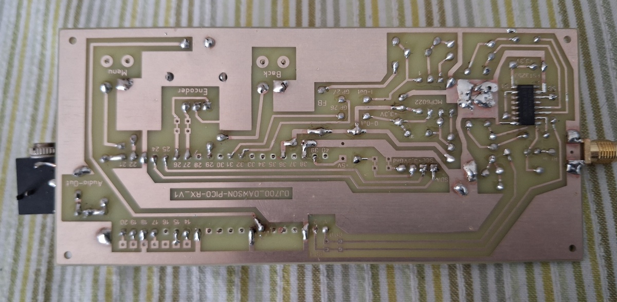
Foto einer geätzten Leiterplatte mit Beschriftungen
Menu, Encoder, Back, FB, Gr, 3.3V, MCP6022, 1-Dot, GP27, 3.3V, D-Out, 5V, 3.3V, SDA, DJ700_DAWSON-PICO-RX_V1, Audio-Out, 20 bis 38, 24 bis 25
in „Raspberry Pi Pico SDR“ · HF, Funk und Felder · · Platinenfotos
-
Bild
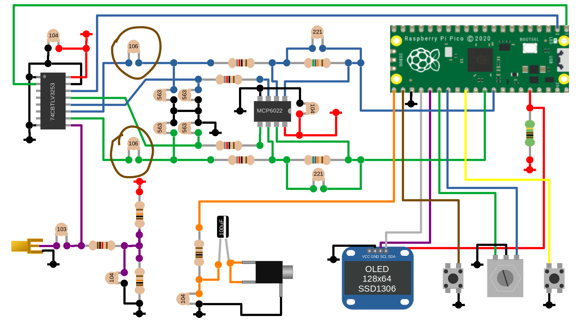
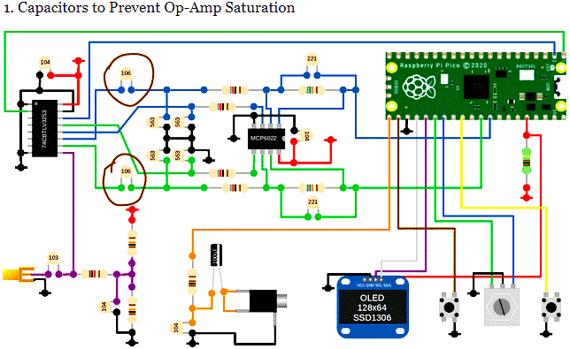
Schaltplan mit Raspberry Pi Pico und OLED Display
1. Capacitors to Prevent Op-Amp Saturation 74ACBTLY3253 106 106 104 104 104 103 563 563 562 561 MCP6022 221 221 Raspberry Pi Pico 2020 BOOTSEL OLED 128x64 SSD1306 VCC GND SCL SDA
in „Raspberry Pi Pico SDR“ · HF, Funk und Felder · · Schaltpläne
-
Bild
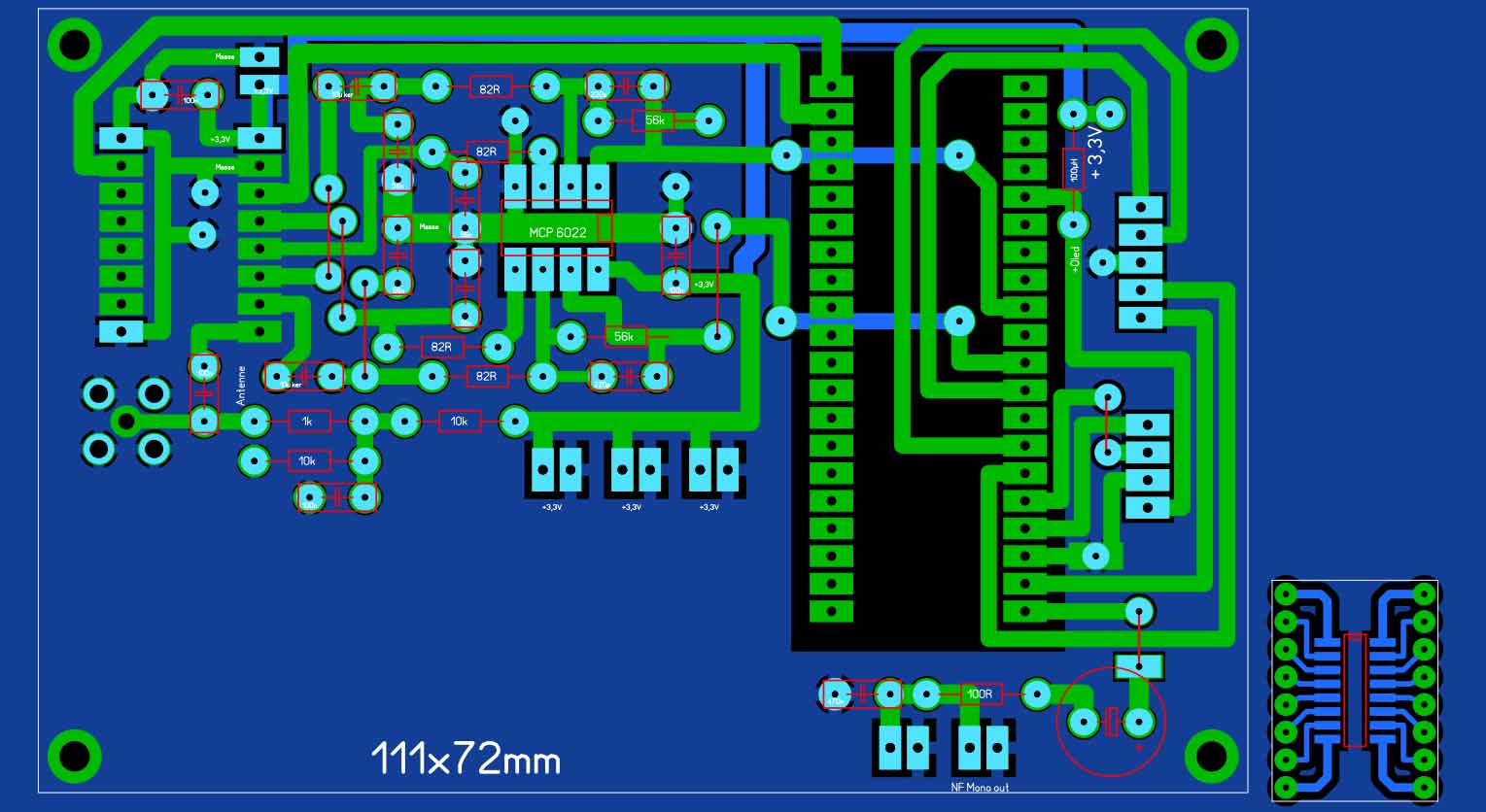
Leiterplatten-Layout einer Elektronikschaltung
82R 56k +3,3V MCP 6022 +3,3V 82R 82R 10k 10k Antenne 1k +3,3V +3,3V +3,3V 111x72mm 100R NF Mana out
in „Raspberry Pi Pico SDR“ · HF, Funk und Felder · · Layouts
-
PDF
MCP3221.pdf
achievable with an the voltage level of AIN is equal to or less than operational amplifier, such as the MCP6022, which has VSS + 1/2 LSB, the resultant code will be 000h. Addi- a closed-loop output impedance of tens of ohms. tionally, if the voltage at AIN is equal to or greater than VDD - 1.5 LSB, the output
in „Suche Bauteilbezeichnung 5-Pin SOT-23 mit "S1SD" Marking“ · Mikrocontroller und Digitale Elektronik ·
-
PDF
Designing_a_digital_compass.pdf
specific to read later, the PIC18F2520 measures the high pulse to compassing are the 2x8 LCD, and the MCP6022/ determine the angle. The MXD2020EL has a tempera- MCP6024 operational amplifiers. The MOSFET ture output that is connected to AN3 on the responsible for creating the Set/Reset pulse is an PIC18F2520

in „Kompassmodul HDMM01 von Pollin“ · Mikrocontroller und Digitale Elektronik ·