-
 Bild
Bild
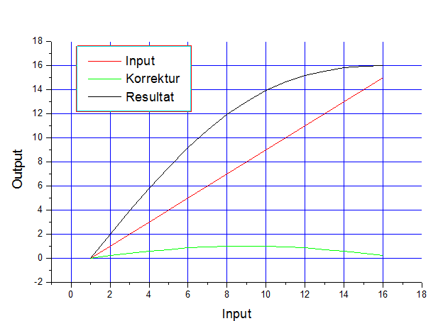
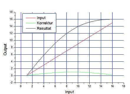
Diagramm von Input, Korrektur und Resultat
Input Korrektur Resultat Output
in „DIY 10kW/20kWh eta=99% Insel ESS Projektvorstellung“ · Haus & Smart Home · · Diagramme
-
 Bild
Bild
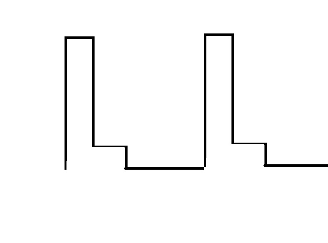
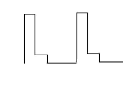
Einfache digitale Wellenform
pwm.jpg
in „IRF1405PBF Mosfet wird zu heiss und verabschiedet sich“ · Analoge Elektronik und Schaltungstechnik · · Oszi-Bilder
-
 Bild
Bild
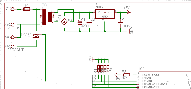
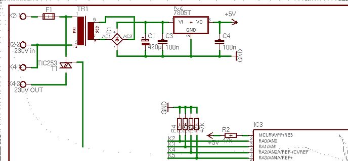
Schaltplan eines Netzteils mit Spannungsregler
K2 230V in F1 TR1 PRI SEC B1 AC2 C1 C3 IC2 7805T VI + VO +5V 420µ 100n 100n GND K4 TIC253 T1 230V OUT GND R4 R3 R2 47k 47k IC3 MCLRWPP/RE3 RAD/AN0 RA1/AN1 RA2/AN2/VREF/CVREF RA3/AN4/VREF +5V
in „230V~ Phasenanschnitt mit PWM ?“ · Mikrocontroller und Digitale Elektronik · · Schaltpläne
-
 Bild
Bild
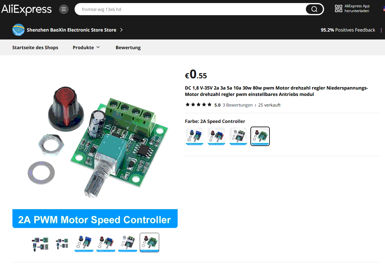
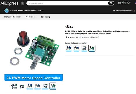
PWM Motor Speed Controller auf AliExpress Webseite
95.2% Positive Feedback Startseite des Shops Produkte Bewertung €0.55 DC 1,8 V-35V 2a 3a 5a 10a 30w pwm Motor drehzahl regler Niederspannungs-Motor drehzahl regler pwm einstellbares Antriebs modul 5.0 3 Bewertungen 25 verkauft Farbe: 2A Speed Controller 2A PWM Motor Speed Controller
in „Brushles motor steuerung pwn TX RX GND“ · Analoge Elektronik und Schaltungstechnik · · Screenshots
-
 Bild
Bild
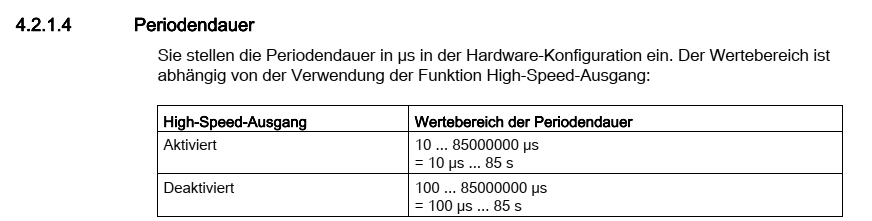
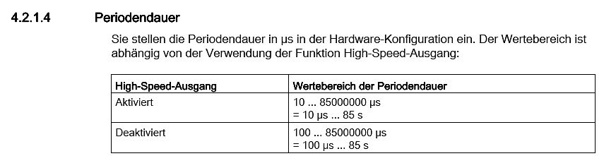
Ausschnitt aus einer technischen Dokumentation zur Periodendauer
4.2.1.4 Periodendauer Sie stellen die Periodendauer in µs in der Hardware-Konfiguration ein. Der Wertebereich ist abhängig von der Verwendung der Funktion High-Speed-Ausgang: High-Speed-Ausgang | Wertebereich der Periodendauer Aktiviert | 10 ... 85000000 µs = 10 µs ... 85 s Deaktiviert | 100 ... 85000000 µs = 100 µs ... 85 s
in „PWM Shifter 24V auf 5V“ · Mikrocontroller und Digitale Elektronik · · Screenshots
-
Datei
pwm.asm
start EQU p3.0 ; Taste START pwm equ p1.7 ; 3-ecksausgang starten: jnb start,takt jmp starten takt: cpl pwm mov a,#11 ws: djnz Acc,ws JMP starten END
in „2051 will nicht“ · Mikrocontroller und Digitale Elektronik ·
-
Datei
PWM.c
#include <inttypes.h> #include <avr/io.h> #include <avr/interrupt.h> #include <avr/signal.h> #include <ioM8.h> void ioinit (void) { /* PORTB als Ausgang */ DDRB = _BV (PB7) | _BV (PB6) | _BV (PB5) | _BV (PB4) | _BV (PB3) | _BV (PB2) | _BV (PB1) | _BV (PB0) ; /* PORTB alle LEDs aus */ PORTB = 0xFF ; /* PORTD PD2 als Eingang / Rest als Ausgang */ DDRD = _BV (PD7) | _BV (PD6) | _BV (PD5) | _BV (PD4) | _BV (PD3) | ~_BV (PD2) | _BV (PD1) | _BV (PD0) ; /* Int0 steigende Flanke / INT0 enable */ MCUCR = _BV (ISC01) | _BV (ISC00); GICR = _BV (INT0); /* Timer0 (8Bit) 1/8 MCU Takt */ TCCR0 = _BV (CS01);
in „C Code Modellbau“ · Mikrocontroller und Digitale Elektronik ·
-
Datei
pwm.c
#include <avr/io.h> #include <avr/interrupt.h> #include <avr/signal.h> void uart_string(unsigned char* data); void UartInit (void); volatile unsigned char VarA; SIGNAL(SIG_INTERRUPT0){ VarA = TCNT0; } int main(void){ UartInit(); unsigned char *Pulsbreite, count1, count2; DDRD = 0x00; //Input(INT0,INT1) DDRB = 0xFF; //LED TCCR0 = _BV(CS02) | _BV(CS00); //1024-prescaleF: (4M/1024) = 3906,25 Hz (0,256ms) GICR = _BV(INT0); //enable interrupt 0 TIMSK = _BV(TOIE0); //Enable timer 0 overflow interrupts. MCUCR = _BV(ISC11) | _BV(ISC10); //steigende fl generiert interrupt TCNT0 = 0; //Zähler zurücksetzen
in „PWM-Timer Problem“ · Mikrocontroller und Digitale Elektronik ·
-
Datei
pwm.c
#include <avr/io.h> #include <avr/interrupt.h> #include <avr/signal.h> void uart_string(unsigned char* data); void UartInit (void); SIGNAL(SIG_INPUT_CAPTURE1){ unsigned char *hilf, *hilf2, flanke; unsigned int timer_wert1, timer_wert2; flanke = ((TCCR1B) & 0x40); if(flanke != 0x00){ //bei steigender flanke timer_wert1 = ICR1; //TCCR1B |= _BV(ICES1); //auf fallende Flanke umstellen uart_string("Pulsbreite\n\r"); itoa(timer_wert1, hilf2,10); uart_string(hilf2); uart_string("\n\r"); TCNT1 = 0; } else{ //bei fallender Flanke wird timer_wert2 = ICR1; //Timer-Register auslesen //TCCR1B = _BV(ICES1);
in „PWM-Timer Problem“ · Mikrocontroller und Digitale Elektronik ·
-
Datei
pwm.c
#include <avr/io.h> #include <avr/interrupt.h> #include <avr/signal.h> #define DDRXLED DDRD #define PORTLED PORTD #define LED1 PD0 #define LED2 PD1 #define LED3 PD2 volatile unsigned char z; volatile unsigned char wert1help; volatile unsigned char wert2help; volatile unsigned char wert3help; volatile unsigned char wert1; volatile unsigned char wert2; volatile unsigned char wert3; SIGNAL(SIG_OVERFLOW0) { if(z++ == 0) // OVERFLOW COUNTER man koennte hier selber auch das Register abfragen { PORTLED &= ~(1<<LED1); // ALLE LED's aus bei 0 PORTLED &= ~(1<<LED2); PORTLED &= ~(1<<LED3); } if(wert1help+
in „PWM mit ATMega8“ · Mikrocontroller und Digitale Elektronik ·
-
Datei
pwm.asm
temp, RAMEND out SP, temp ldi temp, 0xFF ;Port B = Ausgang out DDRB, temp ldi temp,0b10000001 ;8-Bit PWM u.s.w. out TCCR1A,temp ldi temp,1 out OCR1H,temp ldi temp,0 out OCR1L,temp ldi temp,0b00000001 ;CLK als Takt out tccr1b,temp loop: ldi temp,55 out OCR1L,temp rjmp loop
in „PWM-Anfänger-Probleme“ · Mikrocontroller und Digitale Elektronik ·
-
Datei
pwm.c
void pwm_init(void) { // outp((1<<COM1A1) | (1<<COM1A0) | (1<<PWM10), TCCR1A); // invertierter pwm outp((1<<COM1A1) | (1<<PWM10), TCCR1A); // nicht invertierter pwm // outp((1<<CS11), TCCR1B); // vorteiler, div 8 outp((1<<CS10), TCCR1B); // ohne vorteiler } void pwm_set(unsigned char value) { outp(value, OCR1L); // 0 - 255 } // anwendung pwm_init(); // AT90S2313 - PB3, OC1 pwm_set(0); pwm_set(255); // Anderer Schnippsel outp(0x00, OCR1AH); outp(0x00, OCR1AL); outp
in „LCD-Kontrast mit PWM in C ?“ · Mikrocontroller und Digitale Elektronik ·
-
Datei
pwm.c
void pwm_init(void) { // outp((1<<COM1A1) | (1<<COM1A0) | (1<<PWM10), TCCR1A); // invertierter pwm outp((1<<COM1A1) | (1<<PWM10), TCCR1A); // nicht invertierter pwm // outp((1<<CS11), TCCR1B); // vorteiler, div 8 outp((1<<CS10), TCCR1B); // ohne vorteiler } void pwm_set(unsigned char value) { outp(value, OCR1L); // 0 - 255 } // anwendung pwm_init(); // AT90S2313 - PB3, OC1 pwm_set(0); pwm_set(255); // Anderer Schnippsel outp(0x00, OCR1AH); outp(0x00, OCR1AL); outp
in „PWM Beispiel“ · Mikrocontroller und Digitale Elektronik ·
-
Datei
PWM.bas
' PULS WEITEN MODULATION (PWM) ' Sprache: Bascom AVR-Basic (Demoversion 1.11.6.2) ' Getestet mit 8 MHz auf 90S2333.Ausgabewert wird dann ca. 121 mal pro Sekunde ' erneuert. ' 3 Kanäle an Port B0, B1, B2 ' Bewust einfaches Programm zur Erklärung wie eine Software PWM funktionieren kann. ' Timerinterupt, der in gleichmäßigen Abständen ' das Hauptprogramm unterbricht und ein Unterprogramm (Interupthandler) aufruft ' das die Ausgänge ein oder ausschaltet. Im Mittel
in „PWM Problem“ · Mikrocontroller und Digitale Elektronik ·
-
Datei
PWM.bas
' PULS WEITEN MODULATION (PWM) ' Sprache: Bascom AVR-Basic (Demoversion 1.11.6.2) ' Getestet mit 8 MHz auf 90S2333.Ausgabewert wird dann ca. 121 mal pro Sekunde ' erneuert. ' 3 Kanäle an Port B0, B1, B2 ' Bewust einfaches Programm zur Erklärung wie eine Software PWM funktionieren kann. ' Timerinterupt, der in gleichmäßigen Abständen ' das Hauptprogramm unterbricht und ein Unterprogramm (Interupthandler) aufruft ' das die Ausgänge ein oder ausschaltet. Im Mittel
in „Programme in Basic“ · Mikrocontroller und Digitale Elektronik ·
-
Datei
PWM.bas
' PULS WEITEN MODULATION (PWM) ' Sprache: Bascom AVR-Basic (Demoversion 1.11.6.2) ' Getestet mit 8 MHz auf 90S2333.Ausgabewert wird dann ca. 121 mal pro Sekunde ' erneuert. ' 3 Kanäle an Port B0, B1, B2 ' Bewust einfaches Programm zur Erklärung wie eine Software PWM funktionieren kann. ' Timerinterupt, der in gleichmäßigen Abständen ' das Hauptprogramm unterbricht und ein Unterprogramm aufruft ' das die Ausgänge ein oder ausschaltet. Im Mittel ergibt sich dann
in „Mehrkanaliger PWM“ · Mikrocontroller und Digitale Elektronik ·
-
Datei
pwm.bas
= 0 Dim Hi As Byte Dim Lo As Byte Dim A As Byte Dim Phase As Bit Dim Index As Byte Dim Tem As Byte Pwm Alias Portc.0 ' Pwm Ausgang Config Timer0 = Timer , Prescale = 64 On Timer0 Timer0_isr ' bei Timer0 ueberlauf zur sub Config Portd = Input Config Portc = Output Portc = 255 Portd = 255 Enable Timer0 ' timer0 interrupt ein Enable Interrupts ' Global Interrupt ein Lo = 0 ' PWM Anfangswert Phase = True Do Debounce Pind.0 , 0 , Tabelle , Sub ' Taste entprellen an Pind.0 Hi = 255 - Lo Waitms 100 ' Wait 100 ms Loop End Timer0_isr: If Phase = True Then Set Pwm ' LED EIN Timer0
in „Software PWM Bascom“ · Mikrocontroller und Digitale Elektronik ·
-
Datei
pwm.bas
Byte Dim Lo As Byte Dim A As Byte Dim Phase As Bit Dim Index As Byte Dim Los As Byte Dim Ind As Byte Pwm Alias Portc.0 Pw Alias Portc.1 ' Pwm Ausgang Config Timer0 = Timer , Prescale = 8 On Timer0 Timer0_isr ' bei Timer0 ueberlauf zur sub Config Portd = Input Config Portc = Output Portc = 255 Portd = 255
in „LCD-Hintergrund dimmen mit FASTAVR“ · Mikrocontroller und Digitale Elektronik ·
-
Datei
PWM.bas
Device= m8 ' used device $Stack = 32 ' stack depth $Clock = 8.000 ' adjust for used crystal $Timer1 = PWM, 8, PwmA= Inverted, PwmB = Normal , Prescale = 1 $Timer2 = PWM, 8, Inverted, Prescale = 1 Dim n As Byte Set DDRB.3 : Set DDRB.1 : Set DDRB.2 Start Timer1 Start Timer2 n = 0 Do Pwm1A = n Pwm2 = n Pwm1B
in „Besonderheiten OC2 vom Mega8 ?“ · Mikrocontroller und Digitale Elektronik ·
-
Datei
PWM.txt
.include "m8def.inc" .def temp=r16 .def temp2=r17 ldi temp,$ff out ddrb,temp ldi temp,$71 out ICR1L,temp ldi temp2,$02 out ICR1H,temp2 ldi temp,$2e out OCR1AL,temp out OCR1AH,temp2 ldi temp,$59 out OCR1BL,temp out OCR1BH,temp2 ldi temp,0b11110000 out TCCR1A,temp ldi temp,0b00010011 out TCCR1B,temp wait: rjmp wait
in „Problem mit PWM beim Atmega8“ · Mikrocontroller und Digitale Elektronik ·
-
Datei
PWM.asm
Ausgang stellen BSF STATUS, RP0 ;Bank1 BCF TRISC, 2 ;RC2: output=0 BCF STATUS, RP0 ;zuruck auf Bank 0 ; PWM Mode mit CCP1 initialisieren CLRF CCP1CON ;CCP1-Modus aus BSF CCP1CON, CCP1M3 ;CCP1-Modus PWM Mode BSF CCP1CON, CCP1M2 ; ADC vorbereiten ; PortB vorbereiten bsf STATUS, RP0 ;auf Bank 1 umschalten movlw
-
Datei
pwm.c
_1; _pwm_off=pwm_disabled; usart_puts("direction 1"); }else if(pwm_direction==pwm_toshortcut){ _pwm_on=pwm_shortcut; _pwm_off=pwm_shortcut; usart_puts("shortcut"); }else{ _pwm_on=pwm_disabled; _pwm_off=pwm_disabled
in „AVR: 16 Bit PWM funktioniert nur sporadisch“ · Mikrocontroller und Digitale Elektronik ·
-
Datei
pwm.h
PD6 #define pwm_bottomright PD7 #define pwm_direction_0 ((pwm_direction_enabled<<pwm_topleft)+(pwm_direction_disabled<<pwm_topright)+(pwm_direction_disabled<<pwm_bottomleft)+(pwm_direction_enabled<<pwm_bottomright)
in „AVR: 16 Bit PWM funktioniert nur sporadisch“ · Mikrocontroller und Digitale Elektronik ·
-
Datei
pwm.c
#include "../inc/pwm.h" #include "../inc/init.h" #include <avr/io.h> #include <avr/interrupt.h> #include <stdint.h> #include <string.h> volatile uint8_t pwm_values[PWM_CHANNELS]; volatile uint8_t sync; const uint16_t channel_mask
in „RGB Power LED Treiber“ · Analoge Elektronik und Schaltungstechnik ·
-
Datei
PWM.vhd
; PWM_OUT2 : out STD_LOGIC; PWM_OUT3 : out STD_LOGIC); end PWM; architecture Behavioral of PWM is signal SIG_KST : std_logic_vector(10 downto 0):= "10111011100";--1500; begin process (CLK,RST) variable SINNUS1
-
Datei
pwm.txt
'********************************************************************* ' Software PWM einer RGB Led mit Poti Steuerung '********************************************************************* ' Fading aller Farben einer RGB Led mit common Anode (im Code aenderbar) ' auf ATtiny13 an Port PB0 PB1 PB2 durch Soft PWM, da der Tiny13 nur ' zwei Hardware PWM besitzt (OC0A und OC0B). ' Die RGB Led kann natürlich auch durch einzelne Leuchtdioden ersetzt werden. ' Bei mir steuern PB0 - 2 einen ULN2003, der drei 1 Watt
in „"anfänger" 2x3 pwm?“ · Mikrocontroller und Digitale Elektronik ·
-
Datei
pwm.vhd
prescale1 : prescaler port map(clock => clock, -- component => entity i/o clock_out=> clock_sig); pwm1 : pwm_sub port map( clock_in => clock, value_in => value(15 downto 0), counter_in => cnt, en => en, oc => oc1); pwm2 : pwm_sub port map( clock_in => clock, value_in => value(31 downto 16), counter_in => cnt, en => en, oc => oc2); pwm3 : pwm_sub port map( clock_in => clock, value_in => value(47 downto 32), counter_in => cnt, en => en, oc => oc3); pwm4 : pwm_sub port map( clock_in => clock, value_in => value(63 downto 48), counter_in
in „Bit mit dauer Value '0' soll nicht weg optimiert werden (ISE)“ · FPGA, VHDL & Co. ·
-
Datei
pwm.vhd
=> en, -- data_in =>spi_data_in, -- sck =>spi_clk_in, -- reset =>spi_reset_in, -- data_out => new_pwm_value); pwm1 : pwm_sub port map( clock_in => clock, --clock_sig, value_in => pwm_value(15 downto 0), counter_in => cnt, oc => LED1); pwm2 : pwm_sub port map( clock_in => clock, --clock_sig, value_in => pwm_value(31 downto 16), counter_in => cnt, oc => LED2); pwm3 : pwm_sub port map( clock_in => clock, --clock_sig, value_in => pwm_value(47 downto 32), counter_in => cnt, oc => LED3); pwm4 : pwm_sub port
-
Datei
PWM.c
SREG |= (1<<7); //Global Interrupt enable DDRB |= (1<<PB0); //PB0 als Ausgang //TIMER Timer 0 als PWM mit OCR0A als Schaltpunkt an PB0 TCCR0A |= 0x83; //1000xx11 TCCR0B |= 0x01; //00xx0001 TIMSK |= 0x12; //x001001x up_down = 0x00; OCR0A_wert = 0x00; Interrupt = 0x00; while(1) { if(Interrupt >= 0xFF)
in „Nach Interrupt neu initialisierung“ · Mikrocontroller und Digitale Elektronik ·
-
Datei
PWM.asm
r16 ldi r16, (1<<WGM00) | (1<<WGM01) | (1<<COM0A1) | (0<<COM0A0) | (1<<COM0B1) | (0<<COM0B0) ;fast PWM ;set OC0A at top, clear on compare match fuer A und B out TCCR0A, r16 ldi r16, 156 ;zwei werte fuer OCR0x out OCR0A, r16 ldi r16, 12 out OCR0B, r16 ldi r16, (1<<CS00) | (0<<CS01) | (0<<CS02) | (1<<WGM02
in „PWM mit ATtiny2313 an OCnx-Ausgang“ · Mikrocontroller und Digitale Elektronik ·
-
Datei
PWM.c
// CTC Modus 12 TCCR1B=0x19; // Presclaer 1 ICR1H=0x00; ICR1L=0xFF; // Schrittweite 256 CPU-Takte/PWM-Takt OCR1AH=0x00; OCR1AL=0x00; OCR1BH=0x00; OCR1BL=0x00; ASSR=0x00; TCCR2=0x00; TCNT2=0x00; OCR2=0x00; GICR|=0x00; MCUCR=0x00; MCUCSR=0x00; GIFR=0x00; TIMSK=0x20; // Input Capture ISR im CTC Modus 12
in „12bit, 9-Kanal Soft-PWM für LEDs auf Mega16“ · Mikrocontroller und Digitale Elektronik ·
-
Datei
PWM.c
-2730; return result; } int main(void) { TCCR0 = (1<<WGM00)|(1<<WGM01)|(1<<COM01)|(1<<CS00);//Fast PWM Mode,No Prescaling,f=62,5kHz TCNT0 = 0x00;//Timer Null setzen OCR0 = 160;//47% High DDRB |= (1<<PB3);//OC0 als Ausgang uint16_t adc0; char nr[4]; port_init(); lcd_init_c(); fill_screen(0x0000); prints8x14
in „Gemessene Spannung ungleich ADC-Wert“ · Mikrocontroller und Digitale Elektronik ·
-
Datei
PWM.c
-2730; return result; } int main(void) { TCCR0 = (1<<WGM00)|(1<<WGM01)|(1<<COM01)|(1<<CS00);//Fast PWM Mode,No Prescaling,f=62,5kHz TCNT0 = 0x00;//Timer Null setzen OCR0 = 160;//47% High DDRB |= (1<<PB3);//OC0 als Ausgang uint16_t adc0; char nr[10]; port_init(); lcd_init_c(); fill_screen(0x0000); prints8x14
in „Leider noch immer keine Lösung mit ADC“ · Mikrocontroller und Digitale Elektronik ·
-
Datei
PWM.asm
out TIMSK, temp sei loop: rjmp loop timer0_overflow: ; Timer 0 Overflow Handler inc PWMCount ; den PWM Zähler von 0 bis cpi PWMCount, 127 ; 127 zählen lassen brne WorkPWM clr PWMCount WorkPWM: ldi temp, 0b11000000 ; 0 .. Led an, 1 .. Led aus cp PWMCount, ocr_1 ; Ist der Grenzwert für Led 1 erreicht brlt
in „PWM Tutorial“ · Mikrocontroller und Digitale Elektronik ·
-
Datei
pwm.txt
ledpwm.asm --- drive a blue LED with PWM 21/04/2006 ; Copyright (c) 2006 John Honniball .include "tn2313def.inc" ;.include "m8def.inc" .org 0x0000 ; Blue LED on Port B bit 2 .equ LEDPORT = PortB .set LEDBIT =0 ; ##################### equ durch
in „PWM RGB-LED umschalten“ · Mikrocontroller und Digitale Elektronik ·
-
Datei
pwm.txt
ledpwm.asm --- drive a blue LED with PWM 21/04/2006 ; Copyright (c) 2006 John Honniball .include "tn2313def.inc" ;.include "m8def.inc" .org 0x0000 ; Blue LED on Port B bit 2 .equ LEDPORT = PortB .set LEDBIT =0 ; ##################### equ durch
in „PWM RGB-LED umschalten“ · Mikrocontroller und Digitale Elektronik ·
-
Datei
pwm.c
#include <stdio.h> #include <stdlib.h> #include <math.h> #include <string.h> #include <avr/io.h> #include <avr/interrupt.h> #ifndef SIGNAL #include <avr/signal.h> #endif // SIGNAL #include <avr/iom128.h> #include "inc/constants.h" #include "inc/uart.h" #define CMPS03_DDR DDRE #define CMPS03_PORT PORTE #define CMPS03_PIN PINE #define CMPS03_NPIN 4 // PORTE4 volatile long sek; volatile long usek1; volatile long degrees; volatile long usekStart; SIGNAL(SIG_OUTPUT_COMPARE3A) { if(bit_is_set(CMPS03_PIN, CMPS03_NPIN)) usekStart = usek1; if(bit_is_clear(CMPS03_PIN, CMPS03_NPIN)) degrees = usek1 - usekStart
in „Nochmal PWM: was mache ich falsch?“ · Mikrocontroller und Digitale Elektronik ·
-
Datei
PWM.txt
führt zu keinem besseren Ergebnis //Vergleichswert } ISR (SIG_OUTPUT_COMPARE0A) { static uint16_t PWM_zaehler = 0; if (PWM_zaehler <= 1024) { PWM_zaehler++; } else { PWM_zaehler = 0; } //RED PWM if ((PWM_zaehler < LED_red_bright) || (LED_red_bright == 1024)) { PORTB &= ~(1<<PB2); //LED an } else { PORTB |= (1<<PB2); //LED aus } //GREEN PWM if ((PWM_zaehler < LED_green_bright) || (LED_green_bright == 1024)) { PORTA &= ~(1<<PA7); //LED an } else { PORTA |= (1<<PA7); //LED aus } //BLUE PWM if ((PWM_zaehler < LED_blue_bright) || (LED_blue_bright
in „PWM 3x10bit @ 8MHzQ -> nur 63HzOut?“ · Mikrocontroller und Digitale Elektronik ·
-
Datei
PWM.vhd
-- value for LEDs clk_i: in std_logic; reset_n: in std_logic); end PWM; architecture rtl of PWM is type t_state is (IDLE, PLAY, PAUSE); --notwendig für die Realisierung einer State Machine signal s_state : t_state; --mit einem Prozess. signal s_ctr : std_logic_vector (
in „HILFE, ich finde nicht raus wo der Fehler liegt!“ · FPGA, VHDL & Co. ·
-
Datei
PWM.c
/*PWM.c*/ #include <stdio.h> #include <AT89x051.H> sbit PWM_output = P1^4; unsigned char pwm_value, PWM_ON; timer_interrupt_init() { TMOD = (TMOD & 0xF0)|0x22; // Set T_0_1 Mode_2 -> 8bit Reload ET0 = 1;
in „8051 in ISR wird Output_pin nicht immer gesetzt“ · Mikrocontroller und Digitale Elektronik ·
-
Datei
pwm.cc
main (void) { initPorts(); // Unterprogrammaufruf für Initialisierung //Analogwert int awert=0; //für PWM TCCR2 |= (1<<COM21)|(1<<WGM21|(1<<CS22)|(1<<CS21)|(1<<CS20)); do { //Analogwertausgabe awert=Analogwert(); // Analogwert wird mit 6 Bits dargestellt PORTD=awert; // Ausgabe zu Kontrolle des Analogwertes
in „Analog einlesen und als PWM ausgeben“ · Mikrocontroller und Digitale Elektronik ·
-
Datei
pwm.cc
void) { initPorts(); // Unterprogrammaufruf für Initialisierung //Analogwert uint8_t awert=0; //für PWM TCCR2 |= (1<<COM21) | (1<<COM20) | (1<<WGM21)| (1<<WGM20) | (1<<CS22) | (1<<CS21) | (1<<CS20); do { //Analogwertausgabe awert=Analogwert(); // Analogwert wird mit 6 Bits dargestellt PORTD=awert; //
in „Analog einlesen und als PWM ausgeben“ · Mikrocontroller und Digitale Elektronik ·
-
Datei
pwm.cc
void) { initPorts(); // Unterprogrammaufruf für Initialisierung //Analogwert uint8_t awert=0; //für PWM TCCR2 |= (1<<COM21) | (1<<COM20) | (1<<WGM21)| (1<<WGM20) | (1<<CS22) | (1<<CS21) | (1<<CS20); do { //Analogwertausgabe awert=Analogwert(); // Analogwert wird mit 6 Bits dargestellt PORTD=awert; //
in „Analog einlesen und als PWM ausgeben“ · Mikrocontroller und Digitale Elektronik ·
-
Datei
pwm.cc
void) { initPorts(); // Unterprogrammaufruf für Initialisierung //Analogwert uint8_t awert=0; //für PWM TCCR2 |= (1<<COM21) | (1<<COM20) | (1<<WGM21)| (1<<WGM20) | (1<<CS22) | (1<<CS21) | (1<<CS20); do { //Analogwertausgabe awert=Analogwert(); // Analogwert wird mit 6 Bits dargestellt PORTD=awert; //
in „Analog einlesen und als PWM ausgeben“ · Mikrocontroller und Digitale Elektronik ·
-
Datei
pwm.cc
void) { initPorts(); // Unterprogrammaufruf für Initialisierung //Analogwert uint8_t awert=0; //für PWM TCCR2 |= (1<<COM21) | (1<<WGM21)| (1<<WGM20) | (1<<CS22) | (1<<CS21) | (1<<CS20); do { //Analogwertausgabe awert=Analogwert(); // Analogwert wird mit 6 Bits dargestellt PORTD=awert; // Ausgabe zu Kontrolle
in „Analog einlesen und als PWM ausgeben“ · Mikrocontroller und Digitale Elektronik ·
-
Datei
PWM.c
#include <avr/io.h> #include <avr/interrupt.h> #include <stdint.h> #ifndef F_CPU #define F_CPU 3686400UL #endif #include <avr/delay.h> //variablen für LED1 int rlim,glim,blim; int rinc,ginc,binc; //variablen für LED2 int r2lim,g2lim,b2lim; //limits int r2inc,g2inc,b2inc; // increase/decrease of colour int wait,max; int main (void) { //Port declaration DDRB = 0xff; DDRD = 0x00; PORTD |= (1<<PD6) | (1<<PD7); //timer TCCR2 |= (1<<CS20) | (1<<CS22); //Variables wait = 0; max= 300; rlim=-100; glim=200; blim=400; r2lim=0; g2lim=0; b2lim=0; rinc=1; ginc=3; binc=2; r2inc=1; g2inc=3; b2inc=2; while(1){ if
in „LED ansteuerung mit Atmega8“ · Mikrocontroller und Digitale Elektronik ·
-
Datei
PWM.c
(i); return 0; } ISR (TIMER1_COMPA_vect) { switch (ui8which) { case 1 : PORTC &= ~ (1<<PC0); start_PWM(); break; case 2 : PORTC &= ~ (1<<PC1); start_PWM(); break; case 3 : PORTC &= ~ (1<<PC2); start_PWM(); break; case 4 : PORTC &= ~(1<<PC3); OCR2 = TCNT2 + 63; TIMSK |= (1<<OCIE2); TIMSK &= ~ (1<<OCIE1A); break; } } ISR (TIMER2_COMP_vect) { TIMSK |= (1<<OCIE1A); TIMSK &= ~ (1<<OCIE2); start_PWM(); } void start_PWM (void){ ui8which++; if (ui8which == 5){ ui8which = 1; } switch (ui8which){ case 1 : PORTC |= (1<<PC0); OCR1A = TCNT1 + ui16signal0; break; case 2 : PORTC |= (1<<PC1); OCR1A = TCNT1
in „4 Servos mit Atmega8“ · Mikrocontroller und Digitale Elektronik ·
-
Datei
PWM.txt
#include <REG51F.h> void main (void) { int i; int j; P1 &=~0x07; CMOD = 0x02; CCON = 0x40; CCAPM0 = 0x42; CCAP0H = 51; CCAP0L = 51; CCAPM1 = 0x42; CCAP1H = 102; CCAP1L = 102; CCAPM2 = 0x42; CCAP2H = 153; CCAP2L = 153; CCAPM3 = 0x42; CCAP3H = 204; CCAP3L = 204; CCAPM4 = 0x42; CCAP4H = 255; CCAP4L = 255; CH = 0; CL = 0; EC = 1; CR = 1; EA = 1; While (1) { For(j = 0; j<=255; j++) { For(i=0; i<=255; i++) { CCAP0H=j; CCAP1H=j; CCAP2H=j; CCAP3H=j; CCAP4H=j; } } } }
in „PWM : led dimmen“ · Mikrocontroller und Digitale Elektronik ·
-
Datei
PWM.vhd
-- -- Company: -- Engineer: -- -- Create Date: 14:28:29 08/24/2010 -- Design Name: -- Module Name: PWM - Behavioral -- Project Name: -- Target Devices: -- Tool versions: -- Description: -- -- Dependencies: -- -- Revision: -- Revision 0.01 - File Created -- Additional Comments: -- --------------------
in „Sinustabelle mit 2 Geschwindigkeiten“ · FPGA, VHDL & Co. ·
-
Datei
pwm.c
typedef struct { uint16_t value; uint8_t mask; } pwm_pt_t; volatile pwm_pt_t ptbuf1[PWM_CHANNELS]; volatile pwm_pt_t ptbuf2[PWM_CHANNELS]; volatile pwm_pt_t *calcbuf = ptbuf1; volatile pwm_pt_t *intbuf = ptbuf2; volatile uint8_t updated = 0; volatile
in „Soft PWM für LED Controller (RGB mit Multifunktion)“ · Mikrocontroller und Digitale Elektronik ·