Suchergebnisse für "sinus "
Bild
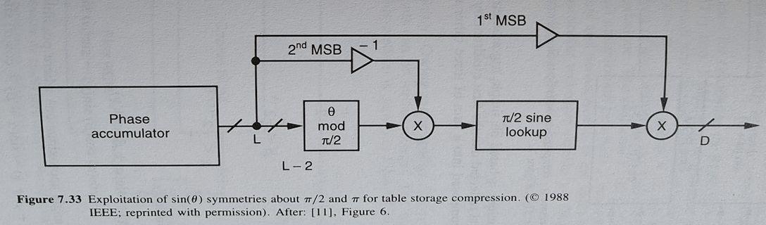
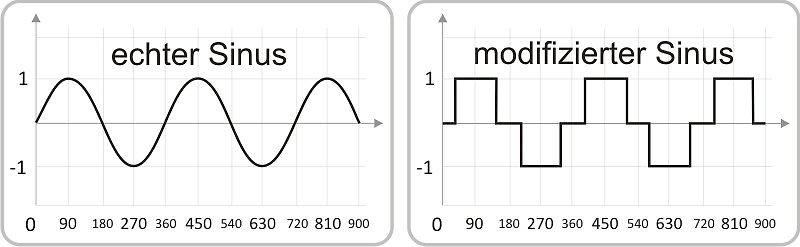
echter Sinus 1 -1 0 90 180 270 360 450 540 630 720 810 900 modifizierter Sinus 1 -1 0 90 180 270 360 450 540 630 720 810 900
in
„Trafo mit Rechteckspannung betreiben?“
·
Analoge Elektronik und Schaltungstechnik
·
12.09.2023 08:18
·
Diagramme
Bild
Bild
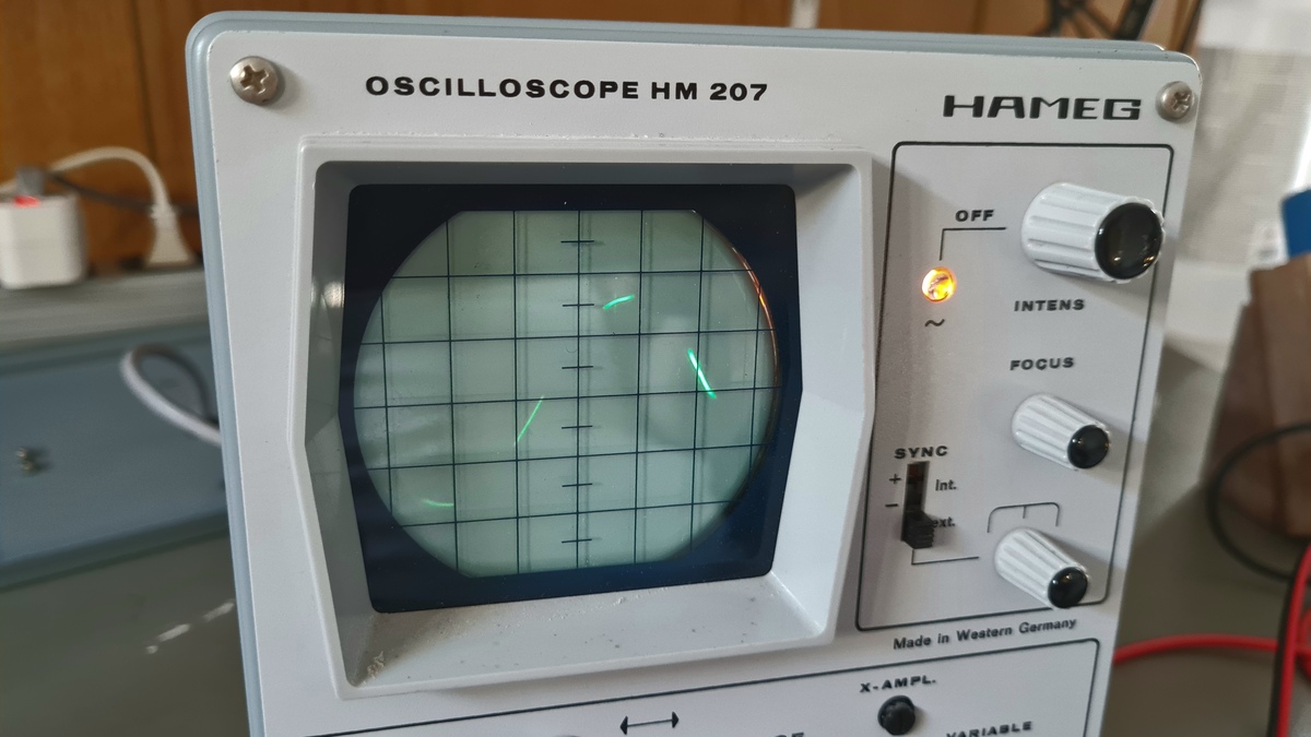
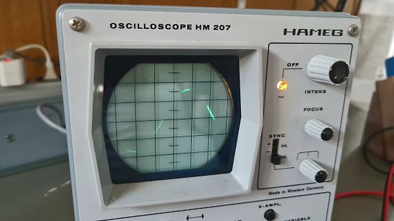
OSCILLOSCOPE HM 207 HAMEG OFF INTENS FOCUS SYNC Int. ext. Made in Western Germany X-AMPL. VARIABLE
in
„Hameg HM207 Osci Defekträtsel“
·
Analoge Elektronik und Schaltungstechnik
·
12.08.2024 09:10
·
Fotos
Bild
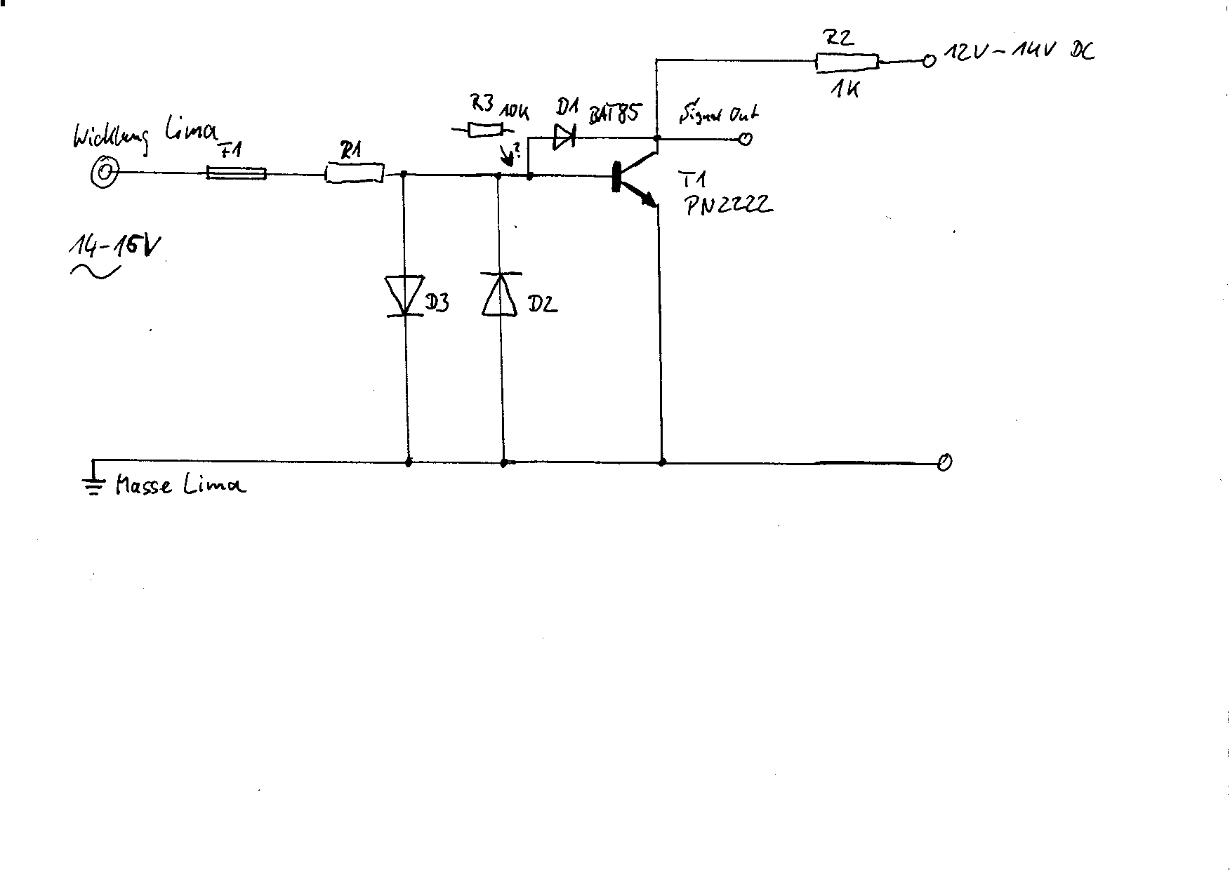
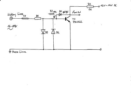
Wicklung Lima, 14-15V, R1, F1, R3 10K, D1 BAT85, T1 PN2222, Signal Out, R2 1K, 12V~14V DC, D3, D2, Masse Lima
in
„Signalaufbereitung aus der Wicklung einer Drehstromlima“
·
Fahrzeugelektronik
·
29.01.2024 14:31
·
Schaltpläne
Bild
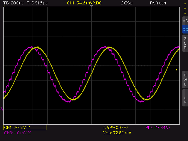
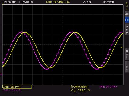
TB: 200 ns T: 9.516 µs CH1: 54.6 mV\DC 2 GSa Refresh CH1 AC DC GND CH1: 20 mV\ f: 999.00 kHz Vpp: 72.80 mV Phs: 27.346 °
in
„Ausgangsfilter DDS AD9833 und AD8051 und Ausgangsverstärker“
·
Mikrocontroller und Digitale Elektronik
·
17.09.2025 16:43
·
Oszi-Bilder
---------------------------------------------------- t0ovfl: out tccr0,r20 ;stop timer0 lpm ;load sinus into r0 out tcnt0,r0 ;reload timer0 cbi portd,6 ;speaker off cbi portd,5 ;speaker off inc ZL cpse ZL,r25 ;at the end? rjmp done mov ZL,r24 ;reload Z ptr done: reti ;--------------------------------
in
„PWM an induktiver Last“
·
Analoge Elektronik und Schaltungstechnik
·
11.10.2006 18:05
/*+++++++++++++++++++++++++++ f Frank Armbruster f f martrikelnr f f 02.12.2004 f f sinus .cpp f f Sinus von x berechnen f +++++++++++++++++++++++++++*/ #include <iostream.h> #include <stdio.h> #define pi 3.1415926535897932384626433832795 double dFakultaet( double); //funktionsdeklaration
in
„sin x mit c berechnen“
·
Softwareentwicklung
·
11.10.2006 20:22
; *************************************************************** ; ; * PWM - Demo: Ausgabe einer Sinus -Schwingung ; ; Benutzung Interrupts, Zugriff auf SRAM, PWM mit T/C 1 ; *************************************************************** ; ; .NOLIST .INCLUDE "4433def.inc" .LIST ; ; ; Benutzte Register
in
„Unverschämt: schwankende PWM-Frequenz“
·
Mikrocontroller und Digitale Elektronik
·
11.10.2006 11:27
Durchlauf AUS1: rrf BYTAUS ; Nächstes Datenbit nach Bit0 schieben AUS2: movfw BYTAUS andlw 0x01 ; Bit0=Sinus =X, Bit1=CS\S2=0, Bit2=Takt=0 iorwf LATI,w ; CS\ sinus 2=1, BCD intern=1 movwf PORTB ; 1. Byte ausgeben, Taktbit ist=0 iorlw 0x02 ; Taktbit auf 1 setzen vorbereiten movwf PORTB ; Taktbit auf 1 setzen
in
„PIC beendet programm nicht“
·
Mikrocontroller und Digitale Elektronik
·
11.10.2006 11:37
#include <avr/io.h> #include <avr/interrupt.h> #include <avr/pgmspace.h> #include <inttypes.h> #include <stdlib.h> #define WERTE 512 #define F_PWM 3906.25 typedef struct{ uint8_t anzahl; uint8_t teiler; uint8_t sinwerte[256]; } data_struct; const uint8_t sinustabelle[512] PROGMEM = {127,129,130,132,133,135,136,138,139,141,143,144,146,147,149,150,152,153,155,156,158,159,161,162,164,165,167,168,170,171,173,174,176,177,178,180,181,183,184,185,187,188,190,191,192,194,195,196,198,199,200,201,203,204,205,206,208,209,210,211,212,213,215,216,217,218,219,220,221,222,223,224,225,226,227,228,229,230,231,232,233,233,234,235,236,237,238,238,239,240,240,241,242,242,243,244,244,245,245,246,247,247,248,248,249,249,249,250,250,251,251,251,252,252,252,252,253,253,253,253,253,254,254,254,254,254,254,254,254,254,254,254,254,254,254,254,253,253,253,253,253,252,252,252,252,251,251,251,250,250,249,249,249,248,248,247,247,246,245,245,244,244,243,242,242,241,240,240,239,238,238,237,236,235,234,233,233,232,231,230,229,228,227,226,225,224,223,222,221,220,219,218,217,216,215,213,212,211,210,209,208,206,205,204,203,201,200,199,198,196,195,194,192,191,190,188,187,185,184,183,181,180,178,177,176,174,173,171,170,168,167,165,164,162,161,159,158,156,155,153,152,150,149,147,146,144,143,141,139,138,136,135,133,132,130,129,127,125,124,122,121,119,118,116,115,113,111,110,108,107,105,104,102,101,99,98,96,95,93,92,90,89,87,86,84,83,81,80,78,77,76,74,73,71,70,69,67,66,64,63,62,60,59,58,56,55,54,53,51,50,49,48,46,45,44,43,42,41,39,38,37,36,35,34,33,32,31,30,29,28,27,26,25,24,23,22,21,21,20,19,18,17,16,16,15,14,14,13,12,12,11,10,10,9,9,8,7,7,6,6,5,5,5,4,4,3,3,3,2,2,2,2,1,1,1,1,1,0,0,0,0,0,0,0,0,0,0,0,0,0,0,0,1,1,1,1,1,2,2,2,2,3,3,3,4,4,5,5,5,6,6,7,7,8,9,9,10,10,11,12,12,13,14,14,15,16,16,17,18,19,20,21,21,22,23,24,25,26,27,28,29,30,31,32,33,34,35,36,37,38,39,41,42,43,44,45,46,48,49,50,51,53,54,55,56,58,59,60,62,63,64,66,67,69,70,71,73,74,76,77,78,80,81,83,84,86,87,89,90,92,93,95,96,98,99,101,102,104,105,107,108,110,111,113,115,116,118,119,121,122,124,125}; const uint8_t teiler[15] = {16,8,6,4,4,3,3,2,2,2,2,2,2,2,2}; uint8_t frequenz = 0; data_struct dataset[2]; volatile uint8_t set = 0; volatile uint8_t newset = 0; volatile uint16_t counter = 0; volatile uint16_t counterpre = 1; data_struct gentable(uint8_t frequenz) { uint8_t i; uint16_t wert; data_struct
in
„Verbesserungsideen zu PWM Sinus“
·
Mikrocontroller und Digitale Elektronik
·
06.06.2009 16:48
0.0000ms 0.0000V 0.0245ms 0.1227V 0.0491ms 0.2453V 0.0736ms 0.3678V 0.0982ms 0.4901V 0.1227ms 0.6121V 0.1473ms 0.7337V 0.1718ms 0.8548V 0.1963ms 0.9755V 0.2209ms 1.0955V 0.2454ms 1.2149V 0.2700ms 1.3336V 0.2945ms 1.4514V 0.3191ms 1.5684V 0.3436ms 1.6844V 0.3682ms 1.7995V 0.3927ms 1.9134V 0.4172ms 2.0262V 0.4418ms 2.1378V 0.4663ms 2.2481V 0.4909ms 2.3570V 0.5154ms 2.4645V 0.5400ms 2.5705V 0.5645ms 2.6750V 0.5890ms 2.7779V 0.6136ms 2.8790V 0.6381ms 2.9785V 0.6627ms 3.0762V 0.6872ms 3.1720V 0.7118ms 3.2659V 0.7363ms 3.3578V 0.7609ms 3.4477V 0.7854ms 3.5355V 0.8099ms 3.6212V 0.8345ms 3.7048V 0.8590ms 3.7860V
in
„LtSpice glättet die Funktion die durch pwl file angegeben wird“
·
Analoge Elektronik und Schaltungstechnik
·
09.07.2009 22:32
, x"21", x"1e", x"1b", x"18", x"15", x"12", x"0f", x"0c", x"09", x"06", x"03" ); begin Result1 <= Sinus _Rom (to_integer(Address1)); Result2 <= Sinus _Rom (to_integer(Address2)); Result3 <= Sinus _Rom (to_integer(Address3)); end process; -- Output registers process begin wait until rising_edge(CLK); --Von 0 to (maxAccum1)/2 : darstellen sinus im Bereich(0,pi) --Von (maxAccum1)/2 to maxAccum1) : darstellen sinus im Bereich(pi,2pi) --D_out1 <= Result1; if (Sign1='1') then for Amplitude in 0 to 25 loop D_out1 <= std_logic_vector(to_unsigned
in
„Amplitude von Sinus ändern in FPGA“
·
FPGA, VHDL & Co.
·
16.02.2010 11:48
********************/ int main (void) { /* Variablen festlegen */ /* 32 Top */const unsigned char sinus _32[ 32]={0,2,3,5,6,8,9,11,12,14,15,16,18,19,20,21,22,24,25,25,26,27,28,28,29,30,30,30,31,31,31,31}; // sinus _32 - 32 Werte für eine viertel Periode #define sinus sinus _32 #define max 32 // Anzahl Speicherzellen
in
„Stabilitätsproblem oder Verständnisproblem bei Timer (PWM) ATmega88“
·
Mikrocontroller und Digitale Elektronik
·
02.03.2010 16:06
UNISIM.VComponents.all; library IEEE; use IEEE.std_logic_1164.ALL; use IEEE.numeric_std.ALL; entity Sinus PWM is Port ( clk : in STD_LOGIC; pwmout : out STD_LOGIC; Data_in : in STD_logic); end Sinus PWM; architecture Behavioral of Sinus PWM is signal sinus : std_logic_vector(7 downto 0); signal sinusplusoffset
in
„Sinustabelle mit 2 Geschwindigkeiten“
·
FPGA, VHDL & Co.
·
10.09.2010 14:12
0 71 100 71 0 -71 -100 -71
in
„frage : testbench“
·
FPGA, VHDL & Co.
·
13.01.2011 16:21
potenzieren (zaehler)*/ double fak = 1.0; /*Die Fakultaet (Zaehler)*/ double sin = 0.0, sinold = 1.0; /*Sinus variable und sinus alt um schleife zu beenden*/ double vorzeichen = 1.0; /*variable fürs Vorzeichen (1 oder -1)*/ int z = 1, k = 1, v = 0; /*Zähler der Schleifen*/ sin=x; while(sin != sinold) { sinold
in
„Sinus Rek“
·
Softwareentwicklung
·
25.11.2006 12:22
=========================== Name : test.c Author : Version : Copyright : Gnu GPl V3 Description : sinus generator ============================================================================ */ #include <stdio.h> #include <stdlib.h> FILE * pFile; void writeDAC(int32_t value) { printf("%d \n",value);
in
„minimalistische Berechnung einer Sinusschwingung“
·
Projekte & Code
·
16.02.2014 06:47
> <script> var fOscSin = 0.0; var fOscCos = 1.0; var fFrq = 0.015; for (var x=0; x<600; x++) { // Sinus erzeugen fOscSin += fFrq * fOscCos; fOscCos -= fFrq * fOscSin; // Amplitude berechnen und Abweichung von Amplitude 1.0 ermitteln fOscCorr = 1.0 +((1.0 - (fOscSin * fOscSin + fOscCos * fOscCos))*0.01
in
„Sinussignal erzeugen“
·
Mikrocontroller und Digitale Elektronik
·
26.02.2019 18:40
#include <X11/Xlib.h> #include <math.h> #define NUM 200 int main(void) { XPoint points[NUM]; Display *d = XOpenDisplay(NULL); int s = DefaultScreen(d); Window w = XCreateSimpleWindow(d, RootWindow(d, s), 0, 0, 600, 300, 0, BlackPixel(d, s), WhitePixel(d, s)); XSelectInput(d, w, ExposureMask | StructureNotifyMask | KeyPressMask); XMapWindow(d, w); for (int loop = 1; loop;) { XEvent e; XNextEvent(d, &e); switch (e.type) { case Expose: XDrawLines(d, w, DefaultGC(d, s), points, NUM, CoordModeOrigin); break; case ConfigureNotify: for (int i = 0 ; i < NUM ; i++) { points[i].x = i * e.xconfigure.width / NUM ; points
in
„Grafik unter Linux“
·
Softwareentwicklung
·
10.07.2020 18:50
time V(sine) 0.000000000000000e+000 0.000000e+000 6.713867187499859e-006 4.601208e-004 1.342773437499972e-005 1.797741e-003 2.014160156249958e-005 4.012860e-003 2.685546874999944e-005 7.105479e-003 3.356933593749930e-005 1.107560e-002 4.028320312499916e-005 1.592321e-002 4.699707031249900e-005 2.164833e-002 5.536760602678454e-005 3.003883e-002 6.373814174107007e-005 3.965250e-002 7.210867745535562e-005 5.048936e-002 8.047921316964115e-005 6.254941e-002 8.884974888392669e-005 7.583263e-002 9.722028459821223e-005 9.033904e-002 1.055908203124978e-004 1.060686e-001 1.165771484374975e-004 1.285590e-001
in
„LTspice Abtastung (Sampling) eines Signals“
·
Analoge Elektronik und Schaltungstechnik
·
10.11.2017 17:01
const uint8_t sinus [256] PROGMEM ={ 127,130,133,136,139,143,146,149,152,155,158,161,164,167,170,173,176,178,181, 184,187,190,192,195,198,200,203,205,208,210,212,215,217,219,221,223,225,227, 229,231,233,234,236,238,239,240,242,243,244,245,247,248,249,249,250,251,252
in
„AVR Synthesizer mit ATxmega128A1“
·
Projekte & Code
·
03.08.2014 10:02
Data Library ofCongress Cataloging-in-Publication Crawford,James A. Frequency synthesizer design handbook/James A. Crawford. Inchudesbibliographical references anindex. ISBN 0-89006-440-7 1 Teency synthesizers. ITitle .F73C73 1994 621.3815°486-dc20 94-165 5 328 In Figure 7.32, all parameters were left unchanged butF, = 640 was selccted to illustrate what can happen when (F,, 2*) > 1 occurs. In this case, the skewed spur levels indicate that elements of both AM and PMare present and the strongest spur component has increased to —-60 dBc. This is substantially worse than that observed in the first
in
„Genauer und schneller Sinus im FPGA“
·
FPGA, VHDL & Co.
·
30.09.2025 23:50
Bild
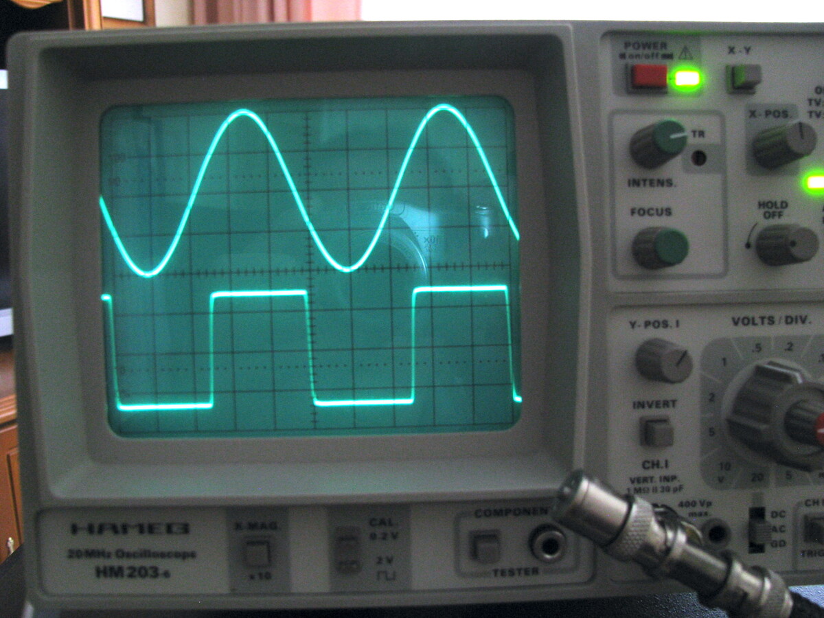
POWER On/off, X-Y, TR, INTENS., FOCUS, HOLD OFF, Y-POS.I, VOLTS/DIV., INVERT, CH.I, VERT. INP., 400 Vp, HAMED, 20MHz Oscilloscope, HM203-e, X MAG., CAL. 2V, COMPONENT TESTER
in
„[V] HAMEG HM203-6 mit Zubehör“
·
Markt
·
20.05.2023 19:30
·
Fotos
0.000000ms 0.0000V 0.024499ms 0.1225V 0.0245ms 0.1225V 0.049099ms 0.2454V 0.0491ms 0.2454V 0.073599ms 0.3677V 0.0736ms 0.3677V 0.098199ms 0.4902V 0.0982ms 0.4902V 0.122699ms 0.6120V 0.1227ms 0.6120V 0.147299ms 0.7338V 0.1473ms 0.7338V 0.171799ms 0.8548V 0.1718ms 0.8548V 0.196299ms 0.9752V 0.1963ms 0.9752V 0.220899ms 1.0955V 0.2209ms 1.0955V 0.245399ms 1.2147V 0.2454ms 1.2147V 0.269999ms 1.3337V 0.2700ms 1.3337V 0.294499ms 1.4513V 0.2945ms 1.4513V 0.319099ms 1.5686V 0.3191ms 1.5686V 0.343599ms 1.6844V 0.3436ms 1.6844V 0.368199ms 1.7997V 0.3682ms 1.7997V 0.392699ms 1.9134V 0.3927ms 1.9134V 0.417199ms
in
„LtSpice glättet die Funktion die durch pwl file angegeben wird“
·
Analoge Elektronik und Schaltungstechnik
·
14.07.2009 22:20
;Sinustabelle (256 Stufen) .db $80,$83,$86,$89,$8C,$8F,$92,$95; 0-7 .db $98,$9B,$9E,$A1,$A4,$A7,$AA,$AD; 8-15 .db $B0,$B3,$B6,$B9,$BB,$BE,$C1,$C3; 16-23 .db $C6,$C9,$CB,$CE,$D0,$D3,$D5,$D7; 24-31 .db $D9,$DC,$DE,$E0,$E2,$E4,$E6,$E7; 32-39 .db $E9,$EB,$ED,$EE,$F0,$F1,$F2,$F4; 40-47 .db $F5,$F6,$F7,$F8,$F9,$FA,$FB,$FC; 48-55 .db $FC,$FD,$FD,$FE,$FE,$FE,$FE,$FF; 56-63 .db $FF,$FF,$FE,$FE,$FE,$FE,$FD,$FD; 64-71 .db $FC,$FC,$FB,$FA,$F9,$F8,$F7,$F6; 72-79 .db $F5,$F4,$F2,$F1,$F0,$EE,$ED,$EB; 80-87 .db $E9,$E7,$E6,$E4,$E2,$E0,$DE,$DC; 88-95 .db $D9,$D7,$D5,$D3,$D0,$CE,$CB,$C9; 96-103 .db $C6,$C3,$C1,$
in
„Sinustabelle“
·
Mikrocontroller und Digitale Elektronik
·
26.12.2008 13:10
#include <avr/pgmspace.h> const unsigned char sinus _40000[] PROGMEM = { 0x80, 0x80, 0x80, 0x80, 0x80, 0x80, 0x80, 0x80, 0x80, 0x80, 0x80, 0x80, 0x80, 0x80, 0x80, 0x80, 0x80, 0x80, 0x80, 0x80, 0x80, 0x80, 0x80, 0x80, 0x80, 0x80, 0x80, 0x80, 0x80, 0x80
in
„monsterarray im PROGMEM“
·
Mikrocontroller und Digitale Elektronik
·
14.02.2007 21:25
#include <avr/io.h> #define sinpin 5 //Ausgabepin des PWM-Sinus unsigned char sinus [40]={127,147,166,185,202,217,230,240,248,252,254,252,248,240,230,217,202,185,166,147,127,107,88,69,52,37,24,14,6,2,0,2,6,14,24,37,52,69,88,107}; //Array mit Sinuswerten int t=1;
in
„Erzeugen eines Sinus mittels PWM“
·
Mikrocontroller und Digitale Elektronik
·
18.12.2010 19:57
#include <avr/io.h> volatile unsigned char sinus [40]={127,147,166,185,202,217,230,240,248,252,254,252,248,240,230,217,202,185,166,147,127,107,88,69,52,37,24,14,6,2,0,2,6,14,24,37,52,69,88,107}; //Array mit Sinuswerten volatile char t=0; //Zählervariable
in
„Erzeugen eines Sinus mittels PWM“
·
Mikrocontroller und Digitale Elektronik
·
19.12.2010 15:00
% Lösung DFT - SINUS fs = 1000; k = 0:1:15; x_k = [1 , 0.707 , 0 , -0.707 , -1 , -0.707 , 0 , 0.707 , 1 , 0.707 , 0 , -0.707 , -1 , -0.707 ,0, 0.707]; N = length(x_k); subplot(2,1,1); stem(k, x_k); xlabel('k'); ylabel(
in
„DFT von einem Sinus Signal“
·
Digitale Signalverarbeitung / DSP / Machine Learning
·
21.05.2008 19:49
Wellenform ;**************************************************************************************** ; Sinus ; frequenz: f1 ; benutzt Sinustabelle aus 256 Werten fuer eine Welle ; ca 24 zyklen pro loop ; f1 = 1 -> 24*256*256 zyklen -> 3,2 Hz ; f1 = 1023 -> 24* 64 zyklen -> 3200 Hz sine movlw 3 movwf PCLATH
in
„Theorie Wechselrichter 12V DC -> 230V AC“
·
Analoge Elektronik und Schaltungstechnik
·
15.12.2012 14:09
FUNKTION_SINUS _270_w brsh FUNKTION_SINUS _270_groesser FUNKTION_SINUS _270_w: cpi temp1, low(270) ; LOW brlo FUNKTION_SINUS _270_FERTIG breq FUNKTION_SINUS _270_FERTIG brsh FUNKTION_SINUS _270_groesser FUNKTION_SINUS _
in
„SINUS - COSINUS / KOSINUS - BEISPIEL (Assembler) ATmega8“
·
Projekte & Code
·
12.10.2006 04:03
#define FALSE 0 #define TRUE !FALSE #include <avr/io.h> #include <avr/interrupt.h> #include <math.h> // program made for a clock of 16MHz // define a vector for sine output! int main( void ) { float pi=3.141592653; int i, sine[91]; for(i=0;i<=90;i++) sine[i] = sin(pi/180 * i)*256; // this will show you the principles of usage of fast pwm on AVR Timers // OCR1A_value (pwm_value) = ((duty cycle in %)/100) *256 // the output frequency can be calculated as follows: // F_out = crystal frequency /(prescaler*256) // / This is referring to 8Bit pwm for 9Bit pwm use 512 and for 10Bit pwm use 1024 instead
in
„kurze Frage zur AVR fast pwm sinus-ausgabe?!“
·
Mikrocontroller und Digitale Elektronik
·
16.10.2011 17:31
#define FALSE 0 #define TRUE !FALSE #include <avr/io.h> #include <avr/interrupt.h> #include <math.h> // program made for a clock of 16MHz volatile int timer_flag; int main( void ) { // define a vector for sine output! float pi=3.141592653; int i = 0, sine[91], neg_half_wave = 0; for(i=0;i<=90;i++) sine[i] = sin(pi/180 * i)*256; // this will show you the principles of usage of fast pwm on AVR Timers // OCR1A_value (pwm_value) = ((duty cycle in %)/100) *256 // the output frequency can be calculated as follows: // F_out = crystal frequency /(prescaler*256) // / This is referring to 8Bit pwm for 9Bit
in
„kurze Frage zur AVR fast pwm sinus-ausgabe?!“
·
Mikrocontroller und Digitale Elektronik
·
16.10.2011 18:42
Bild
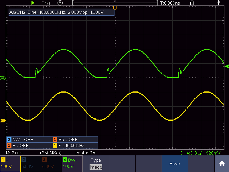
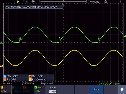
Trig A T:0,000ns AGCH2-Sine, 100.0000kHz, 2.000Vpp, 1.000V 4 BW- 2 NW : OFF 3 Ma : OFF 3 F : OFF 1 F : 100.0KHz M: 2.0us (250MS/s) Depth:10M CH4:DC- 820mV 1: 1.00V 2: 5.00V 3: 5.00V 4: 1.00V
in
„Massiever Überschwinger bei OP LT1213“
·
Analoge Elektronik und Schaltungstechnik
·
31.07.2023 10:10
·
Oszi-Bilder
1.00006066506084E-5 ; 0.00762339342439562 1.00014687248443E-5 ; 0.0184564988104108 1.00018040480372E-5 ; 0.0226702585660385 1.00020757221293E-5 ; 0.0260841752524693 1.00026190703135E-5 ; 0.0329119705521221 1.00037057666819E-5 ; 0.0465673642945834 1.0004058491813E-5 ; 0.0509996278959089 1.00045474878388E-5 ; 0.0571441734610539 1.00046521279697E-5 ; 0.0584590322548098 1.00047347905666E-5 ; 0.0594977288139568 1.00048768485434E-5 ; 0.0612827517762852 1.00050692851728E-5 ; 0.0637007928756408 1.00054390318985E-5 ; 0.0683467619953927 1.0005765654098E-5 ; 0.0724508106365116 1.00060718818885E-5 ; 0.0762985566956648
in
„DFT mit Matlab berechnen“
·
Softwareentwicklung
·
16.09.2015 17:21
time V(sine) 0.000000000000000e+000 5.000050e-001 1.999999998947288e-009 5.000151e-001 5.000000004307115e-009 5.000302e-001 9.000000002201691e-009 5.000502e-001 9.400000000603370e-009 5.000523e-001 6.779999996946770e-008 5.003458e-001 1.261999999383320e-007 5.006394e-001 1.845999999071964e-007 5.009329e-001 2.429999998760607e-007 5.012265e-001 3.013999998449250e-007 5.015200e-001 3.597999998137894e-007 5.018136e-001 4.181999997826535e-007 5.021071e-001 8.277999995684460e-007 5.041659e-001 8.444819982744711e-007 5.042498e-001 9.445739905106221e-007 5.047529e-001 1.002960985978241e-006 5.050463e-001
in
„LTspice Daten richtig exportieren“
·
PC Hard- und Software
·
09.11.2017 13:03
Modulationsdemo // Variablen volatile uint16_t frequenz; volatile uint8_t amplitude, phase; const int8_t sinus [256] PROGMEM = { 0, 3, 6, 9, 12, 16, 19, 22, 25, 28, 31, 34, 37, 40, 43, 46, 49, 51, 54, 57, 60, 63, 65, 68, 71, 73, 76, 78, 81, 83, 85, 88, 90, 92, 94, 96, 98, 100, 102, 104, 106, 107, 109, 111, 112
in
„Arduino Micro SPWM“
·
Mikrocontroller und Digitale Elektronik
·
24.03.2022 21:05
const uint8_t Sinus [256] PROGMEM = { 127, 130, 133, 136, 139, 143, 146, 149, 152, 155, 158, 161, 164, 167, 170, 173, 176, 178, 181, 184, 187, 190, 192, 195, 198, 200, 203, 205, 208, 210, 212, 215, 217, 219, 221, 223,
in
„Attiny2313 Timer16 Bit, Normal Mode, unsauber“
·
Mikrocontroller und Digitale Elektronik
·
11.03.2021 18:56
Modulationsdemo // Variablen volatile uint16_t frequenz; volatile uint8_t amplitude, phase; const int8_t sinus [256] PROGMEM = { 0, 3, 6, 9, 12, 16, 19, 22, 25, 28, 31, 34, 37, 40, 43, 46, 49, 51, 54, 57, 60, 63, 65, 68, 71, 73, 76, 78, 81, 83, 85, 88, 90, 92, 94, 96, 98, 100, 102, 104, 106, 107, 109, 111, 112
in
„E-Magnet mit Sinus steuern“
·
Analoge Elektronik und Schaltungstechnik
·
23.07.2023 12:07
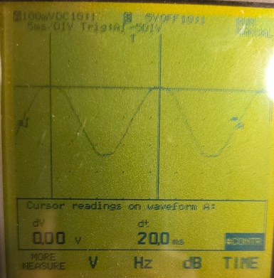
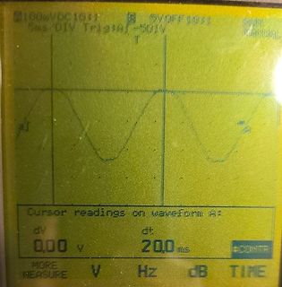
Bild
Bild
100mVDC10SI 5V OFF10SI
5ms/DIV Trig:A1 -50IV
T
A
Cursor readings on waveform A:
dV dt
0,00 v 20,0 ms
MORE MEASURE V Hz dB TIME
in
„QNCT16L 1000/1 Stromwandler an Atmega8 ADC. Spannung verzerrt.“
·
Mikrocontroller und Digitale Elektronik
·
19.04.2026 22:23
·
Fotos
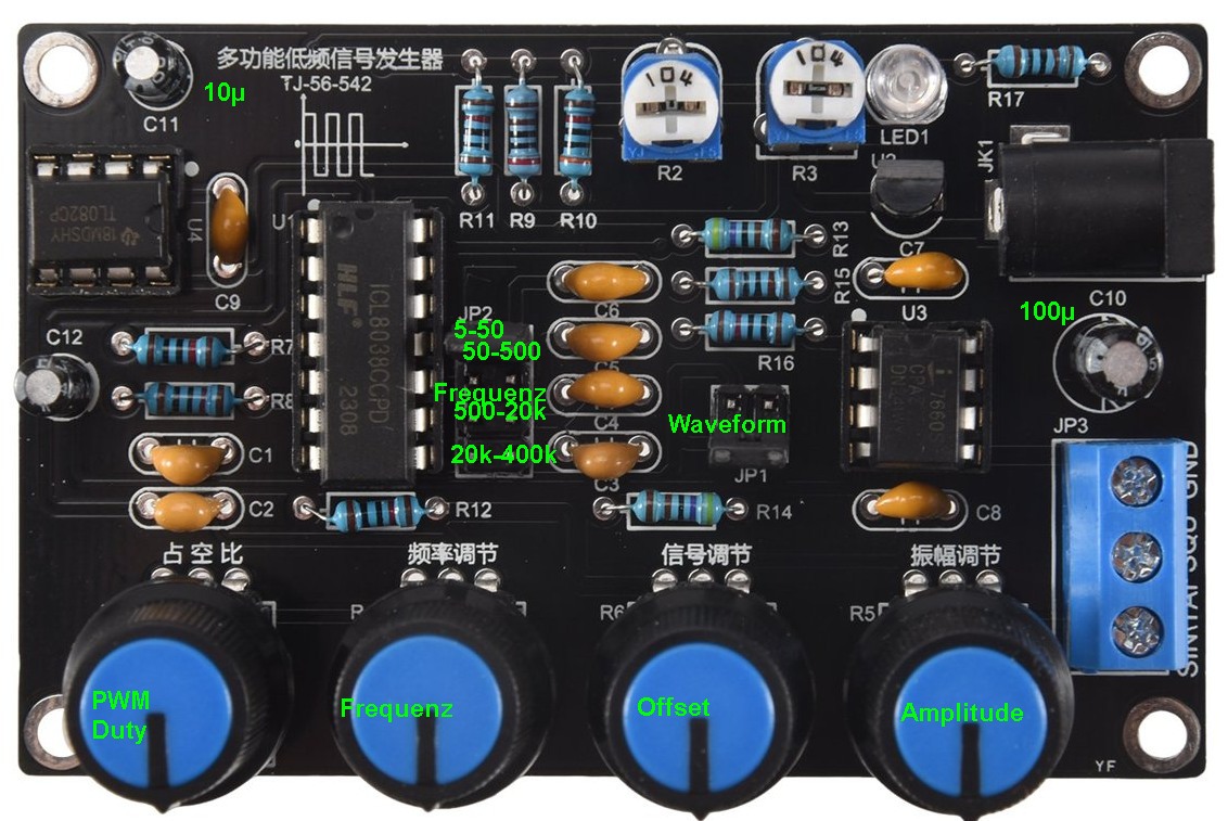
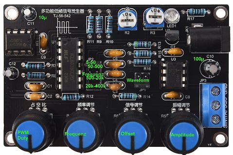
Bild
多功能低频信号发生器 TJ-56-542 10µ C11 TL02CP U4 U1 ICL8038CPD 2308 JP2 5-50 50-500 Frequenz 500-2k 29k-400k Waveform JP1 C6 C4 C8 C1 C2 C12 R11 R9 R10 R2 R3 R15 R13 R16 R7 R8 R12 R14 R5 R6 104 104 100µ C10 LED1 U3 C7 JP3 SINAI SQO GND 占空比 Frequenz调节 信号调节 振幅调节 PWM Duty Offset Amplitude YF
in
„Sinusgenerator Bausatz ohne / mit fehlerhafter Stückliste“
·
Analoge Elektronik und Schaltungstechnik
·
24.09.2026 18:31
·
Platinenfotos
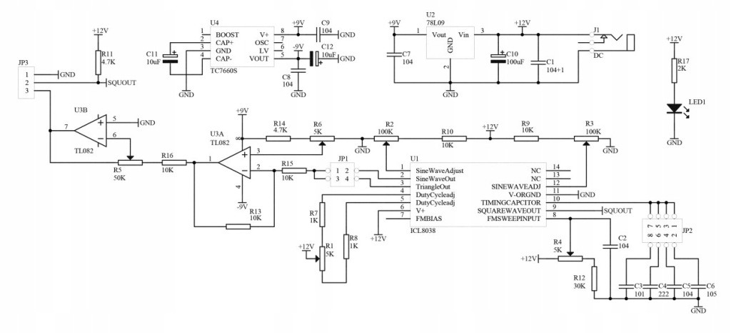
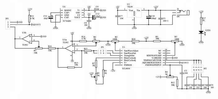
Bild
JP3, GND, SQUOUT, U3B, TL082, GND, R5 50K, R16 10K, U3A, TL082, R15 10K, R13 10K, R7 1K, R1 5K, +12V, +9V, U4, TC7660S, BOOST, CAP+, OSC, GND, CAP-, VOUT, C11 10uF, R11 4.7K, C8 104, C12 10uF, C9 104, U2, 78L09, +9V, Vout, Vin, C10 100uF, J1, DC, +12V, R17 2K, LED1, GND, R2 100K, R10 10K, R9 10K, R3 100K, GND, U1, ICL8038, JP1, SineWaveAdjust, SineWaveOut, TriangleOut, DutyCycleadj, DutyCycleadj, V+, FMSWEINPUT, FMSWEINPUT, SQUAREWAVE OUT, R4 5K, C2 104, R12 30K, C3 101, C4 222, C5 105, C6 104, JP2, GND
in
„Sinusgenerator Bausatz ohne / mit fehlerhafter Stückliste“
·
Analoge Elektronik und Schaltungstechnik
·
24.09.2026 18:31
·
Schaltpläne
Bild
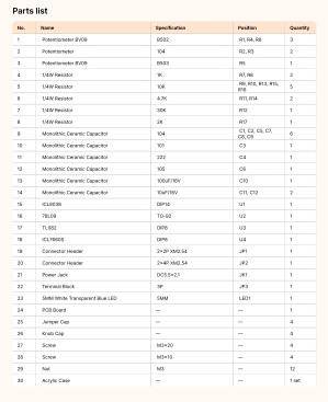
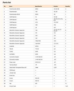
Parts list
No. Name Specification Position Quantity
1 Potentiometer BV09 B502 R1, R4, R6 3
2 Potentiometer 104 R2, R3 2
3 Potentiometer BV09 B503 R5 1
4 1/4W Resistor 9K R7, R8 2
5 1/4W Resistor 10K R9, R10, R13, R15, R16 5
6 1/4W Resistor 4.7K R11, R14 2
7 1/4W Resistor 33K R12 1
8 1/4W Resistor 2K R17 1
9 Monolithic Ceramic Capacitor 104 C1, C2, C5, C7, C8, C9 6
10 Monolithic Ceramic Capacitor 101 C3 1
11 Monolithic Ceramic Capacitor 222 C4 1
12 Monolithic Ceramic Capacitor 105 C6 1
13 Monolithic Ceramic Capacitor 100uF/16V C10 1
14 Monolithic Ceramic Capacitor 10uF/16V C11, C12 2
16 IC L3539
in
„Sinusgenerator Bausatz ohne / mit fehlerhafter Stückliste“
·
Analoge Elektronik und Schaltungstechnik
·
24.09.2026 18:31
·
Screenshots
Bild
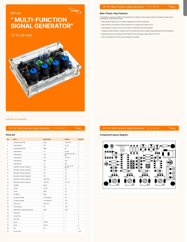
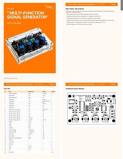
DIY Kit "Multi-Function Signal Generator" TZ-TJ-56-542
Parts list
No. Name Specification Position Quantity
1 Potentiometer RV002 RV,RE 1
2 Potentiometer 104 RV,RE 2
3 Potentiometer RV003 RV,RE 2
4 LED RV004 RV,RE 1
5 LED RV005 RV,RE 1
6 LED RV006 RV,RE 1
7 LED RV007 RV,RE 1
8 LED RV008 RV,RE 1
9 LED RV009 RV,RE 1
10 Ceramic Capacitor 104 C1, C2, C3, C4, C5, C6 6
11 Ceramic Capacitor 222 C7 1
12 Ceramic Capacitor 104 C8 1
13 Ceramic Capacitor 106 C9 1
14 Ceramic Capacitor 104 C10, C12 2
15 IC LM358 U1 1
16 IC TL082 U2 1
17 IC TL082 U3 1
18 IC LM324 U4 1
19 Connector Header 2*P,W50-54 JP1
20 Connector
in
„Sinusgenerator Bausatz ohne / mit fehlerhafter Stückliste“
·
Analoge Elektronik und Schaltungstechnik
·
24.09.2026 18:31
·
Screenshots
Bild
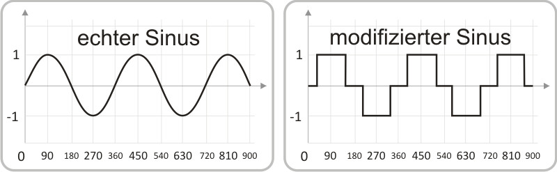
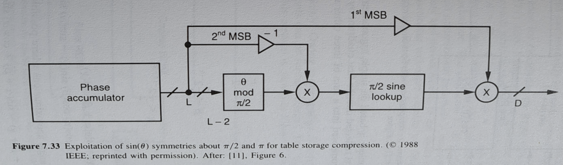
1st MSB
2nd MSB
Phase accumulator
L
θ mod π/2
L - 2
π/2 sine lookup
D
Figure 7.33 Exploitation of sin(θ) symmetries about π/2 and π for table storage compression. (© 1988 IEEE; reprinted with permission). After: [11], Figure 6.
in
„Genauer und schneller Sinus im FPGA“
·
FPGA, VHDL & Co.
·
30.09.2025 15:12
·
Diagramme
weiter abwärts zählen RETURN ;********************************************************************** Sinus ; Periodendauer 4515 Arbeitszyklen, ; fosc 4MHz -> fsin = 1s/4,5515ms = 221,5Hz movlw high Table_Sinus movwf pntr1 ;HByte Tabelle (page) Sinus _Loop1: movlw low Table_Sinus movwf pntr0 ;LByte Zeiger
in
„DAC-R2R-Netzwerk mit PIC16F84“
·
Mikrocontroller und Digitale Elektronik
·
29.06.2013 15:30
Sinustabelle einlesen ------------------------------------------------- sinustabelle: process file sinus _file: text; variable file_line: line; -- variable str_sinus _in: string; variable sinus _in: integer; begin file_open(sinus _file,"sinus .txt",READ_MODE); for j in 0 to 7 loop readline (sinus _file,file_line); -- read (file_line, str_sinus _in); -- assert (false) -- report str_sinus _in -- severity note; read (file_line, sinus _in); sinetable(j) <= sinus _in; end loop; wait; end process sinustabelle; -- Sinus erzeugen -------------------
in
„frage : testbench“
·
FPGA, VHDL & Co.
·
13.01.2011 16:21
) { ADCSRA|=(1<<ADSC); Analog_Ergebnis = ADC/102.4; if(Analog_Ergebnis<=1) { Analog_Ergebnis=1; } sinus _grad=sinus _grad+Analog_Ergebnis; grad_in_rad(sinus _grad); if(Phasenverschieber<=2) { Schwingung_1=sin(sinus _rad)*115+125; Schaltstufe_2=Schwingung_1; } if(Phasenverschieber>=5) { //Schwingung_2=sin(sinus _rad+2.094395)*115+125; Schwingung_2=sin(sinus _rad+4)*115+125; Schaltstufe_2=Schwingung_2; } } }
in
„Sinus Phasenverschiebung mittels PWM (C)“
·
Mikrocontroller und Digitale Elektronik
·
15.10.2011 15:03
Vollschritt Nr Grad Sinus Cosinus Sinus 4Bit Cosinus 4Bit Sinus 5Bit Cosinus 5Bit 1 45 0,7071067812 0,7071067812 11 11 22 22 2 135 0,7071067812 -0,7071067812 11 -11 22 -22 3 225 -0,7071067812 -0,7071067812 -11 -11 -22 -22 4 315 -0,7071067812 0,7071067812 -11 11 -22 22 Halbschritt Nr Grad Sinus Cosinus Sinus 4Bit Cosinus 4Bit Sinus 5Bit Cosinus 5Bit 1 45 0,7071067812 0,7071067812 11 11 22 22 2 90 1,0000000000 0,0000000000 15 0 31 0 3 135 0,7071067812 -0,7071067812 11 -11 22 -22 4 180 0,0000000000
in
„Wer kann kann mir ein Prpgrammschreiben?“
·
Mikrocontroller und Digitale Elektronik
·
08.03.2008 11:59

 Bild
Bild
 Bild
Bild
 Bild
Bild
 Bild
Bild
 Bild
Bild
 Bild
Bild

 Bild
Bild
 Bild
Bild
 Bild
Bild
 Bild
Bild
 Bild
Bild
 Bild
Bild
 Bild
Bild
 Bild
Bild