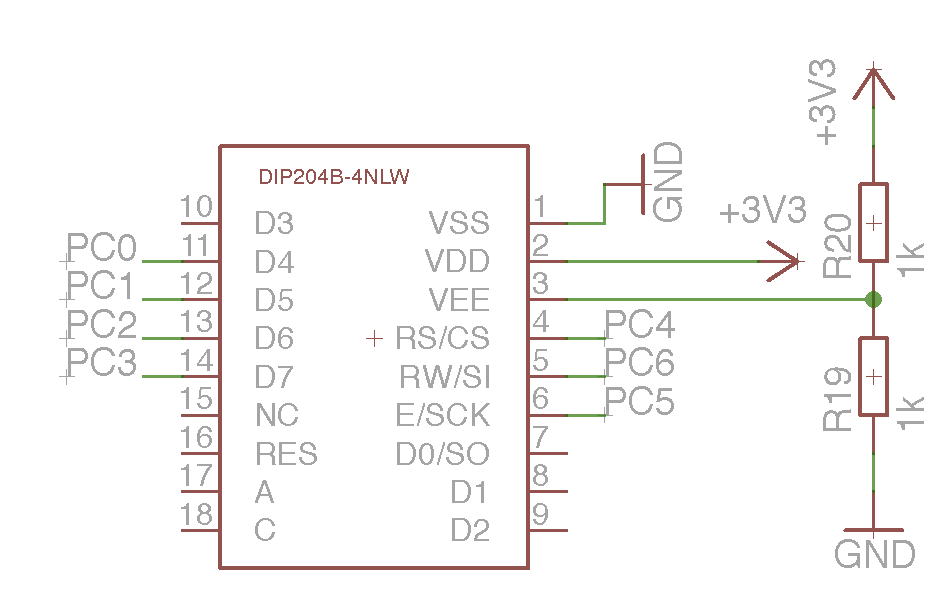
1 | #if (__GNUC__ * 100 + __GNUC_MINOR__) < 303
|
2 | #error "This library requires AVR-GCC 3.3 or later, update to newer AVR-GCC compiler !"
|
3 | #endif
|
4 |
|
5 | #include <inttypes.h>
|
6 | #include <avr/pgmspace.h>
|
7 |
|
8 | /**
|
9 | * @name Definitions for MCU Clock Frequency
|
10 | * Adapt the MCU clock frequency in Hz to your target.
|
11 | */
|
12 | #define XTAL 1000000 /**< clock frequency in Hz, used to calculate delay timer */
|
13 |
|
14 |
|
15 | /**
|
16 | * @name Definition for LCD controller type
|
17 | * Use 0 for HD44780 controller, change to 1 for displays with KS0073 controller.
|
18 | */
|
19 | #define LCD_CONTROLLER_KS0073 1 /**< Use 0 for HD44780 controller, 1 for KS0073 controller */
|
20 |
|
21 | /**
|
22 | * @name Definitions for Display Size
|
23 | * Change these definitions to adapt setting to your display
|
24 | */
|
25 | #define LCD_LINES 4 /**< number of visible lines of the display */
|
26 | #define LCD_DISP_LENGTH 20 /**< visibles characters per line of the display */
|
27 | #define LCD_LINE_LENGTH 0x40 /**< internal line length of the display */
|
28 | #define LCD_START_LINE1 0x00 /**< DDRAM address of first char of line 1 */
|
29 | #define LCD_START_LINE2 0x20 /**< DDRAM address of first char of line 2 */
|
30 | #define LCD_START_LINE3 0x40 /**< DDRAM address of first char of line 3 */
|
31 | #define LCD_START_LINE4 0x60 /**< DDRAM address of first char of line 4 */
|
32 | #define LCD_WRAP_LINES 0 /**< 0: no wrap, 1: wrap at end of visibile line */
|
33 |
|
34 |
|
35 | #define LCD_IO_MODE 1 /**< 0: memory mapped mode, 1: IO port mode */
|
36 | #if LCD_IO_MODE
|
37 | /**
|
38 | * @name Definitions for 4-bit IO mode
|
39 | * Change LCD_PORT if you want to use a different port for the LCD pins.
|
40 | *
|
41 | * The four LCD data lines and the three control lines RS, RW, E can be on the
|
42 | * same port or on different ports.
|
43 | * Change LCD_RS_PORT, LCD_RW_PORT, LCD_E_PORT if you want the control lines on
|
44 | * different ports.
|
45 | *
|
46 | * Normally the four data lines should be mapped to bit 0..3 on one port, but it
|
47 | * is possible to connect these data lines in different order or even on different
|
48 | * ports by adapting the LCD_DATAx_PORT and LCD_DATAx_PIN definitions.
|
49 | *
|
50 | */
|
51 | #define LCD_PORT PORTC /**< port for the LCD lines */
|
52 | #define LCD_DATA0_PORT LCD_PORT /**< port for 4bit data bit 0 */
|
53 | #define LCD_DATA1_PORT LCD_PORT /**< port for 4bit data bit 1 */
|
54 | #define LCD_DATA2_PORT LCD_PORT /**< port for 4bit data bit 2 */
|
55 | #define LCD_DATA3_PORT LCD_PORT /**< port for 4bit data bit 3 */
|
56 | #define LCD_DATA0_PIN 0 /**< pin for 4bit data bit 0 */
|
57 | #define LCD_DATA1_PIN 1 /**< pin for 4bit data bit 1 */
|
58 | #define LCD_DATA2_PIN 2 /**< pin for 4bit data bit 2 */
|
59 | #define LCD_DATA3_PIN 3 /**< pin for 4bit data bit 3 */
|
60 | #define LCD_RS_PORT LCD_PORT /**< port for RS line */
|
61 | #define LCD_RS_PIN 4 /**< pin for RS line */
|
62 | #define LCD_RW_PORT LCD_PORT /**< port for RW line */
|
63 | #define LCD_RW_PIN 6 /**< pin for RW line */
|
64 | #define LCD_E_PORT LCD_PORT /**< port for Enable line */
|
65 | #define LCD_E_PIN 5 /**< pin for Enable line */
|
66 |
|
67 | #elif defined(__AVR_AT90S4414__) || defined(__AVR_AT90S8515__) || defined(__AVR_ATmega64__) || \
|
68 | defined(__AVR_ATmega8515__)|| defined(__AVR_ATmega103__) || defined(__AVR_ATmega128__) || \
|
69 | defined(__AVR_ATmega161__) || defined(__AVR_ATmega162__)
|
70 | /*
|
71 | * memory mapped mode is only supported when the device has an external data memory interface
|
72 | */
|
73 | #define LCD_IO_DATA 0xC000 /* A15=E=1, A14=RS=1 */
|
74 | #define LCD_IO_FUNCTION 0x8000 /* A15=E=1, A14=RS=0 */
|
75 | #define LCD_IO_READ 0x0100 /* A8 =R/W=1 (R/W: 1=Read, 0=Write */
|
76 | #else
|
77 | #error "external data memory interface not available for this device, use 4-bit IO port mode"
|
78 |
|
79 | #endif
|
80 |
|
81 |
|
82 | /**
|
83 | * @name Definitions for LCD command instructions
|
84 | * The constants define the various LCD controller instructions which can be passed to the
|
85 | * function lcd_command(), see HD44780 data sheet for a complete description.
|
86 | */
|
87 |
|
88 | /* instruction register bit positions, see HD44780U data sheet */
|
89 | #define LCD_CLR 0 /* DB0: clear display */
|
90 | #define LCD_HOME 1 /* DB1: return to home position */
|
91 | #define LCD_ENTRY_MODE 2 /* DB2: set entry mode */
|
92 | #define LCD_ENTRY_INC 1 /* DB1: 1=increment, 0=decrement */
|
93 | #define LCD_ENTRY_SHIFT 0 /* DB2: 1=display shift on */
|
94 | #define LCD_ON 3 /* DB3: turn lcd/cursor on */
|
95 | #define LCD_ON_DISPLAY 2 /* DB2: turn display on */
|
96 | #define LCD_ON_CURSOR 1 /* DB1: turn cursor on */
|
97 | #define LCD_ON_BLINK 0 /* DB0: blinking cursor ? */
|
98 | #define LCD_MOVE 4 /* DB4: move cursor/display */
|
99 | #define LCD_MOVE_DISP 3 /* DB3: move display (0-> cursor) ? */
|
100 | #define LCD_MOVE_RIGHT 2 /* DB2: move right (0-> left) ? */
|
101 | #define LCD_FUNCTION 5 /* DB5: function set */
|
102 | #define LCD_FUNCTION_8BIT 4 /* DB4: set 8BIT mode (0->4BIT mode) */
|
103 | #define LCD_FUNCTION_2LINES 3 /* DB3: two lines (0->one line) */
|
104 | #define LCD_FUNCTION_10DOTS 2 /* DB2: 5x10 font (0->5x7 font) */
|
105 | #define LCD_CGRAM 6 /* DB6: set CG RAM address */
|
106 | #define LCD_DDRAM 7 /* DB7: set DD RAM address */
|
107 | #define LCD_BUSY 7 /* DB7: LCD is busy */
|
108 |
|
109 | /* set entry mode: display shift on/off, dec/inc cursor move direction */
|
110 | #define LCD_ENTRY_DEC 0x04 /* display shift off, dec cursor move dir */
|
111 | #define LCD_ENTRY_DEC_SHIFT 0x05 /* display shift on, dec cursor move dir */
|
112 | #define LCD_ENTRY_INC_ 0x06 /* display shift off, inc cursor move dir */
|
113 | #define LCD_ENTRY_INC_SHIFT 0x07 /* display shift on, inc cursor move dir */
|
114 |
|
115 | /* display on/off, cursor on/off, blinking char at cursor position */
|
116 | #define LCD_DISP_OFF 0x08 /* display off */
|
117 | #define LCD_DISP_ON 0x0C /* display on, cursor off */
|
118 | #define LCD_DISP_ON_BLINK 0x0D /* display on, cursor off, blink char */
|
119 | #define LCD_DISP_ON_CURSOR 0x0E /* display on, cursor on */
|
120 | #define LCD_DISP_ON_CURSOR_BLINK 0x0F /* display on, cursor on, blink char */
|
121 |
|
122 | /* move cursor/shift display */
|
123 | #define LCD_MOVE_CURSOR_LEFT 0x10 /* move cursor left (decrement) */
|
124 | #define LCD_MOVE_CURSOR_RIGHT 0x14 /* move cursor right (increment) */
|
125 | #define LCD_MOVE_DISP_LEFT 0x18 /* shift display left */
|
126 | #define LCD_MOVE_DISP_RIGHT 0x1C /* shift display right */
|
127 |
|
128 | /* function set: set interface data length and number of display lines */
|
129 | #define LCD_FUNCTION_4BIT_1LINE 0x20 /* 4-bit interface, single line, 5x7 dots */
|
130 | #define LCD_FUNCTION_4BIT_2LINES 0x28 /* 4-bit interface, dual line, 5x7 dots */
|
131 | #define LCD_FUNCTION_8BIT_1LINE 0x30 /* 8-bit interface, single line, 5x7 dots */
|
132 | #define LCD_FUNCTION_8BIT_2LINES 0x38 /* 8-bit interface, dual line, 5x7 dots */
|
133 |
|
134 |
|
135 | #define LCD_MODE_DEFAULT ((1<<LCD_ENTRY_MODE) | (1<<LCD_ENTRY_INC) )
|

 LCD.png
(10 KB)
LCD.png
(10 KB)