Hallo zusammen,

Ich bin gerade an meinem Schulprojekt und habe die Schaltung von einem
led cube nachgebaut.

http://www.instructables.com/id/LED-Cube-4x4x4/step10/Program-the-microcontroller/

nun habe ich mit einem AVR Dragon die hex datei auf den Mega16
geschrieben und das quarz fuse auf extmedxtalres_64kck_64ms gestellt.

nun habe ich einmal einen Layer an port A angeschlossen und an den GND
Layer 0 Angeschlossen. Aber es tut sich nichts. Auch die 2 Leds, die
leuchten sollten (für den bootvorgang) leuchten nicht.

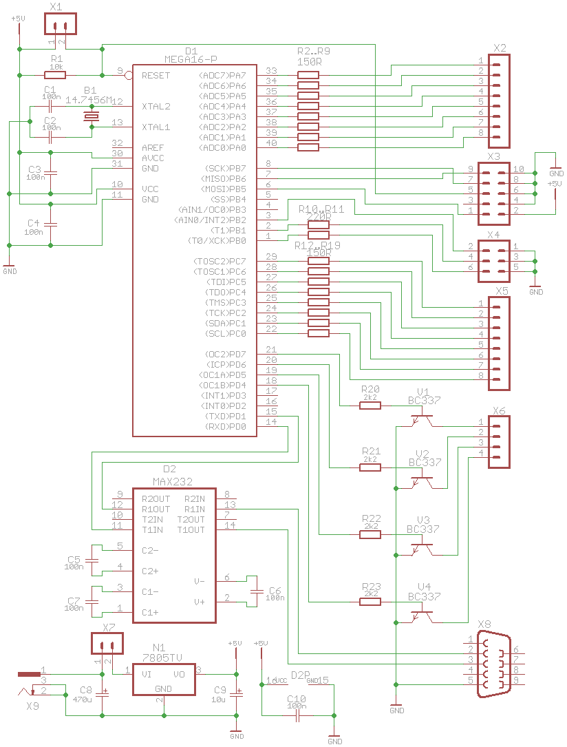
anbei ein Foto von meinem Schaltplan (eventuell ist da ein Fehler)


Besten Dank
Die Kondensatoren des 232 müssen an den Anschlüssen + und - nach GND und
nicht gegen einandner geschaltet werden, sowie ich das noch im Kopf
habe.

Der 7805 hat keine Abblockkondensatoren.

Welchen Zweck genau erfüllt X1 parallel zu dem Widerstand?


Ingo
Berni schrieb:> okay werde das mal ändern.>> aber daran wird es nicht gelegen sein, da auch mit internem quarz nichts> gelaufen ist.
Das wiederrum glaub ich sofort. Weil es nämlich keinen 'internenb Quarz'
gibt.
Das was da intern die Taktversorgung machen kann ist ein RC-Schwingkreis
und kein Quarz.
Hat dein Brennprogramm irgendwas in Richtung 'Fehler' von sich gegeben?
Kannst du zb die µC-Kennung auslesen?
Wenn du dein Brennprogramm den µC auslesen lässt, klappt das?

(Die Frage ist: läuft der µC grundsätzlich? Wenn ja, dann wirst du halt
einen Fehler im Programm haben oder in deiner LED-Beschaltung stimmt was
nicht. Daher ist es immer ganz gut, wenn man für erste Tests den
simpelst möglichen Test macht: Einfach eine LED an den Pin - anderes
Ende an Masse (+Vorwiderstand) und nachsehen ob die LED leuchtet, wenn
du den Pin auf 1 setzt. Gegentest: Die LED darf nicht leuchten, wenn du
den Pin auf 0 setzt. Jede Hadrware-Komponente mehr ist eine zusätzliche
Schicht, die selber wieder Fehler haben kann.
Nö ist nicht der ganze Code ! Weil ich nirgends sehen kann was LED_PORT
ist und wo er ist. Und ohne das LED_PORT irgendwo definiert ist würde
das Programm gar nicht Compiliert werden können. Dann such mal in deinem
Projektordner wo LED_PORT herkommt.
[c]

// ############################################
//
// 4x4x4 LED Cube project
// By Christian Moen 2008
// chr@syntaks.org
// Lisence: GPL
//
// ############################################

#include <avr/io.h>
#include <avr/interrupt.h>
#include <avr/pgmspace.h>

// Define USART stuff
// CPU speed and baud rate:
#define FOSC 14745600
#define BAUD 9600
// Are used to calculate the correct USART timings
#define MYUBRR (((((FOSC * 10) / (16L * BAUD)) + 5) / 10) - 1)


// Define masks used for status LEDs and input buttons.
#define LED_GREEN 0x01
#define LED_RED 0x02
#define BUTTON 0x08
// Define port used for status and input.
#define LED_PORT PORTB
#define BUTTON_PORT PORTB


// Define masks for the layer select.
#define LAYER1 0x80
#define LAYER2 0x40
#define LAYER3 0x20
#define LAYER4 0x10
#define LAYERS 0xf0 // All layers
#define LAYERS_R 0x0f // The inverse of the above.
#define LAYER_PORT PORTD

// Define LED grid ports
// Each of the grid ports are connected to two rows of leds.
// The upper 4 bits is one row, the lower 4 bits are one row.
#define GRID1 PORTC
#define GRID2 PORTA


void ioinit (void); // initiate IO on the AVR
void bootmsg (void); // blink some leds to indicate boot or reboot
void delay_ms (uint16_t x); // delay function used throughout the
program
void led_red(unsigned char state); // led on or off
void led_green(unsigned char state);
void launch_effect (int effect); // effect program launcher

// *** Cube buffer ***
// The 3D image displayed on the cube is buffered in a 2d array 'cube'.
// The 1st dimension in this array is the Z axis of the cube.
// The 2nd dimension of the array is the Y axis.
// Each byte is a stripe of leds running along the X axis at the given
// Z and Y coordinates.
// Only the 4 lower bits are used, since the cube is only 4x4x4.
// This buffer design was chosen to have code compatability with a 8x8x8
cube.
// "volatile" makes the variables reachable from within the interrupt
functions
volatile unsigned char cube[4][4];

// We sometimes want to draw into a temporary buffer so we can modify it
// before writing it to the cube buffer.
// e.g. invert, flip, reverse the cube..
volatile unsigned char tmpcube[4][4];

// What layer the interrupt routine is currently showing.
volatile unsigned char current_layer;

// Low level geometric functions
#include "draw.c"

// Static animation data
#include "frames.c"

// Fancy animations to run on the cube
#include "effect.c"


int main (void)
{
  // Initiate IO ports and peripheral devices.
  ioinit();

  // Indicate that the device has just booted.
  bootmsg();

  int x;
  int i;
  int z;

  // Set the layer to start drawing at
  current_layer = 0x00;

  // Enable interrupts to start drawing the cube buffer.
  // When interrupts are enabled, ISR(TIMER2_COMP_vect)
  // will run on timed intervalls.
  sei();

  // Main program loop.
  while (1)
  {
    for (i=0;i<13;i++)
    {
      launch_effect(i);
    }
    // Comment the loop above and uncomment the line below
    // if you want the effects in random order (produced some bugs.. )
    //launch_effect(rand()%13);
  }

}

// Launches one of those fancy effects.
void launch_effect (int effect)
{
  switch (effect)
  {
    // Lights all the layers one by one
    case 0:
      loadbar(1000);
      break;

    // A pixel bouncing randomly around
    case 1:
      // blink
      boingboing(150,500,0x03,0x01);
      break;

    // Randomly fill the cube
    // Randomly empty the cube
    case 2:
      fill(0x00);
      random_filler(100,1,500,1);
      random_filler(100,1,500,0);
      break;

    // Send voxels randomly back and forth the Z axis
    case 3:
      sendvoxels_rand_z(150,500,2000);
      break;

    // Spinning spiral
    case 4:
      effect_spiral(1,75,1000);
      break;

    // A coordinate bounces randomly around the cube
    // For every position the status of that voxel is toggled.
    case 5:
      // toggle
      boingboing(150,500,0x03,0x02);
      break;

    // Random raindrops
    case 6:
      effect_rain(20,5000,3000,500);
      break;

    // A snake randomly bounce around the cube.
    case 7:
      // snake
      boingboing(150,500,0x03,0x03);
      break;

    // Spinning plane
    case 8:
      effect_spinning_plane(1,50,1000);
      break;

    // set x number of random voxels, delay, unset them.
    // x increases from 1 to 20 and back to 1.
    case 9:
      random_2();
      break;

    // Set all 64 voxels in a random order.
    // Unset all 64 voxels in a random order.
    case 10:
      random_filler2(200,1);
      delay_ms(2000);
      random_filler2(200,0);
      delay_ms(1000);
      break;

    // bounce a plane up and down all the directions.
    case 11:
      flyplane("z",1,1000);
      delay_ms(2000);
      flyplane("y",1,1000);
      delay_ms(2000);
      flyplane("x",1,1000);
      delay_ms(2000);
      flyplane("z",0,1000);
      delay_ms(2000);
      flyplane("y",0,1000);
      delay_ms(2000);
      flyplane("x",0,1000);
      delay_ms(2000);
      break;

    // Fade in and out at low framerate
    case 12:
      blinky2();
      break;
  }
}

// ** Diagnostic led functions **

// Set or unset the red LED
void led_red(unsigned char state)
{
  if (state == 0x00)
  {
    LED_PORT &= ~LED_RED;
  } else
  {
    LED_PORT |= LED_RED;
  }
}

// Set or unset the green LED
void led_green(unsigned char state)
{
  if (state == 0x00)
  {
    LED_PORT &= ~LED_GREEN;
  } else
  {
    LED_PORT |= LED_GREEN;
  }
}


// Cube buffer draw interrupt routine
ISR(TIMER2_COMP_vect)
{

  // AND the reverse bitmask onto the layer port.
  // This disables all the layers. rendering all the leds off.
  // We don't want to see the cube updating.
  LAYER_PORT &= LAYERS_R;

  // Take the current 2D image at the current layer along the Z axis
  // and place it on the LED grid.
  GRID1 = (0x0f & cube[current_layer][0]) | (0xf0 &
(cube[current_layer][1] << 4));
  GRID2 = (0x0f & cube[current_layer][2]) | (0xf0 &
(cube[current_layer][3] << 4));

  // Enable the apropriate layer
  LAYER_PORT |= (0x01 << (7 - current_layer));

  // The cube only has 4 layers (0,1,2,3)
  // If we are at layer 3 now, we want to go back to layer 0.
  if (current_layer++ == 3)
    current_layer = 0;
}

void ioinit (void)
{
  // ### Initiate I/O

  // Data Direction Registers
  // Bit set to 1 means it works as an output
  // Bit set to 1 means it is an input
  DDRA = 0xff;  // Inner cube byte
  DDRB = 0xf7;  // ISP and 0-1: led. 3: button
  DDRC = 0xff;  // Outer cube byte
  DDRD = 0xff;  // Layer select

  // Set all ports OFF, and enable pull up resistors where needed.
  PORTA = 0x00;
  PORTC = 0x00;
  PORTB = 0x08; // Enable pull up button.
  PORTD = 0x00;

  // ### Initiate timers and USART

  // Frame buffer interrupt
  TCNT2 = 0x00;  // initial counter value = 0;
  TIMSK |= (1 << OCIE2); // Enable CTC interrupt

  // Every 1024th cpu cycle, a counter is incremented.
  // Every time that counter reaches 15, it is reset to 0,
  // and the interrupt routine is executed.
  // 14745600/1024/15 = 960 times per second
  // There are 4 layers to update..
  // 14745600/1024/15/4 = 240 FPS
  // == flicker free :)
  OCR2 = 15;       // interrupt at counter = 15
  TCCR2 = 0x05;     // prescaler = 1024
  TCCR2 |= (1 << WGM01);  // Clear Timer on Compare Match (CTC) mode


  // Initiate RS232
  // USART Baud rate: 9600
  UBRRH = MYUBRR >> 8;
  UBRRL = MYUBRR;
  // UCSR0C - USART control register
  // bit 7-6      sync/ascyn 00 = async,  01 = sync
  // bit 5-4      parity 00 = disabled
  // bit 3        stop bits 0 = 1 bit  1 = 2 bits
  // bit 2-1      frame length 11 = 8
  // bit 0        clock polarity = 0
  UCSRC  = 0b10000110;
  // Enable RS232, tx and rx
  UCSRB = (1<<RXEN)|(1<<TXEN);
  UDR = 0x00; // send an empty byte to indicate powerup.

}


// Blink the status LEDs a little to indicate that the device has just
booted.
// This is usefull to see if an error is making the device reboot when
not supposed to.
// And it looks cool.
void bootmsg (void)
{
  int i;
  LED_PORT |= LED_GREEN;
  for (i = 0; i < 2; i++)
  {
    // Blinky
    delay_ms(1000);
    LED_PORT &= ~LED_GREEN;
    LED_PORT |= LED_RED;
    // Blink
    delay_ms(1000);
    LED_PORT &= ~LED_RED;
    LED_PORT |= LED_GREEN;
  }
  delay_ms(1000);
  LED_PORT &= ~LED_GREEN;
}


// Delay function used in graphical effects.
void delay_ms(uint16_t x)
{
  uint8_t y, z;
  for ( ; x > 0 ; x--){
    for ( y = 0 ; y < 90 ; y++){
      for ( z = 0 ; z < 6 ; z++){
        asm volatile ("nop");
      }
    }
  }
}
[c/]

da hat sich doch glatt der halbe code versteckt

sorry
siehe da alles durchgemessen und sie leuchtet schon mal !

worans gelegen ist kann ich nicht sagen hex ist die selbe wie vorher
polarität an der led auch und der schalter ist auch drann ?!

ich bin mal kurtz im keller die matrix zu testen


schonmal riesen danke!

 schaltplan.png
(15 KB)
schaltplan.png
(15 KB)