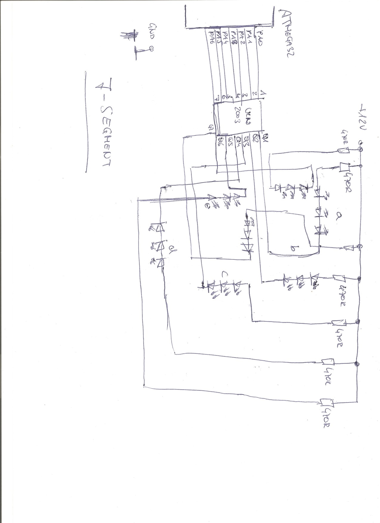
1 | #include <mega32.h>
|
2 | #include <stdio.h>
|
3 | #include <delay.h>
|
4 |
|
5 |
|
6 | unsigned char zahl_0=0x3f;
|
7 | unsigned char zahl_1=0x86;
|
8 | unsigned char zahl_2=0x5b;
|
9 | unsigned char zahl_3=0x4f;
|
10 | unsigned char zahl_4=0x66;
|
11 | unsigned char zahl_5=0x6d;
|
12 | unsigned char zahl_6=0x7d;
|
13 | unsigned char zahl_7=0x87;
|
14 | unsigned char zahl_8=0x00;
|
15 | unsigned char zahl_9=0x6f;
|
16 |
|
17 | interrupt [EXT_INT0] void ext_int0_isr(void) //Externer Interrupt (Tasten einlesen)
|
18 | {
|
19 |
|
20 |
|
21 | }
|
22 |
|
23 | void main(void)
|
24 | {
|
25 | // Declare your local variables here
|
26 |
|
27 | // Input/Output Ports initialization
|
28 | // Port A initialization
|
29 |
|
30 | DDRA=(1<<DDA7) | (1<<DDA6) | (1<<DDA5) | (1<<DDA4) | (1<<DDA3) | (1<<DDA2) | (1<<DDA1) | (1<<DDA0);
|
31 | PORTA=(1<<PORTA7) | (1<<PORTA6) | (1<<PORTA5) | (1<<PORTA4) | (1<<PORTA3) | (1<<PORTA2) | (1<<PORTA1) | (1<<PORTA0);
|
32 |
|
33 | // Port B initialization
|
34 |
|
35 | DDRB=(0<<DDB7) | (0<<DDB6) | (0<<DDB5) | (0<<DDB4) | (0<<DDB3) | (0<<DDB2) | (0<<DDB1) | (0<<DDB0);
|
36 | PORTB=(0<<PORTB7) | (0<<PORTB6) | (0<<PORTB5) | (0<<PORTB4) | (0<<PORTB3) | (0<<PORTB2) | (0<<PORTB1) | (0<<PORTB0);
|
37 |
|
38 | // Port C initialization
|
39 | DDRC=(0<<DDC7) | (0<<DDC6) | (0<<DDC5) | (0<<DDC4) | (0<<DDC3) | (0<<DDC2) | (0<<DDC1) | (0<<DDC0);
|
40 | PORTC=(0<<PORTC7) | (0<<PORTC6) | (0<<PORTC5) | (0<<PORTC4) | (0<<PORTC3) | (0<<PORTC2) | (0<<PORTC1) | (0<<PORTC0);
|
41 |
|
42 | // Port D initialization
|
43 | DDRD=(0<<DDD7) | (0<<DDD6) | (0<<DDD5) | (0<<DDD4) | (0<<DDD3) | (0<<DDD2) | (0<<DDD1) | (0<<DDD0);
|
44 | PORTD=(0<<PORTD7) | (0<<PORTD6) | (0<<PORTD5) | (0<<PORTD4) | (0<<PORTD3) | (0<<PORTD2) | (0<<PORTD1) | (0<<PORTD0);
|
45 |
|
46 | // Timer/Counter 0 initialization
|
47 | // Clock source: System Clock
|
48 | // Clock value: Timer 0 Stopped
|
49 | // Mode: Normal top=0xFF
|
50 | // OC0 output: Disconnected
|
51 | TCCR0=(0<<WGM00) | (0<<COM01) | (0<<COM00) | (0<<WGM01) | (0<<CS02) | (0<<CS01) | (0<<CS00);
|
52 | TCNT0=0x00;
|
53 | OCR0=0x00;
|
54 |
|
55 | // Timer/Counter 1 initialization
|
56 | // Clock source: System Clock
|
57 | // Clock value: Timer1 Stopped
|
58 | // Mode: Normal top=0xFFFF
|
59 | // OC1A output: Discon.
|
60 | // OC1B output: Discon.
|
61 | // Noise Canceler: Off
|
62 | // Input Capture on Falling Edge
|
63 | // Timer1 Overflow Interrupt: Off
|
64 | // Input Capture Interrupt: Off
|
65 | // Compare A Match Interrupt: Off
|
66 | // Compare B Match Interrupt: Off
|
67 | TCCR1A=(0<<COM1A1) | (0<<COM1A0) | (0<<COM1B1) | (0<<COM1B0) | (0<<WGM11) | (0<<WGM10);
|
68 | TCCR1B=(0<<ICNC1) | (0<<ICES1) | (0<<WGM13) | (0<<WGM12) | (0<<CS12) | (0<<CS11) | (0<<CS10);
|
69 | TCNT1H=0x00;
|
70 | TCNT1L=0x00;
|
71 | ICR1H=0x00;
|
72 | ICR1L=0x00;
|
73 | OCR1AH=0x00;
|
74 | OCR1AL=0x00;
|
75 | OCR1BH=0x00;
|
76 | OCR1BL=0x00;
|
77 |
|
78 | // Timer/Counter 2 initialization
|
79 | // Clock source: System Clock
|
80 | // Clock value: Timer2 Stopped
|
81 | // Mode: Normal top=0xFF
|
82 | // OC2 output: Disconnected
|
83 | ASSR=0<<AS2;
|
84 | TCCR2=(0<<PWM2) | (0<<COM21) | (0<<COM20) | (0<<CTC2) | (0<<CS22) | (0<<CS21) | (0<<CS20);
|
85 | TCNT2=0x00;
|
86 | OCR2=0x00;
|
87 |
|
88 | // Timer(s)/Counter(s) Interrupt(s) initialization
|
89 | TIMSK=(0<<OCIE2) | (0<<TOIE2) | (0<<TICIE1) | (0<<OCIE1A) | (0<<OCIE1B) | (0<<TOIE1) | (0<<OCIE0) | (0<<TOIE0);
|
90 |
|
91 | // External Interrupt(s) initialization
|
92 | // INT0: On
|
93 | // INT0 Mode: Falling Edge
|
94 | // INT1: Off
|
95 | // INT2: Off
|
96 | GICR|=(0<<INT1) | (1<<INT0) | (0<<INT2);
|
97 | MCUCR=(0<<ISC11) | (0<<ISC10) | (1<<ISC01) | (0<<ISC00);
|
98 | MCUCSR=(0<<ISC2);
|
99 | GIFR=(0<<INTF1) | (1<<INTF0) | (0<<INTF2);
|
100 |
|
101 | // USART initialization
|
102 | // USART disabled
|
103 | UCSRB=(0<<RXCIE) | (0<<TXCIE) | (0<<UDRIE) | (0<<RXEN) | (0<<TXEN) | (0<<UCSZ2) | (0<<RXB8) | (0<<TXB8);
|
104 |
|
105 | // Analog Comparator initialization
|
106 | // Analog Comparator: Off
|
107 | ACSR=(1<<ACD) | (0<<ACBG) | (0<<ACO) | (0<<ACI) | (0<<ACIE) | (0<<ACIC) | (0<<ACIS1) | (0<<ACIS0);
|
108 | SFIOR=(0<<ACME);
|
109 |
|
110 | // ADC initialization
|
111 | // ADC disabled
|
112 | ADCSRA=(0<<ADEN) | (0<<ADSC) | (0<<ADATE) | (0<<ADIF) | (0<<ADIE) | (0<<ADPS2) | (0<<ADPS1) | (0<<ADPS0);
|
113 |
|
114 | // SPI initialization
|
115 | // SPI disabled
|
116 | SPCR=(0<<SPIE) | (0<<SPE) | (0<<DORD) | (0<<MSTR) | (0<<CPOL) | (0<<CPHA) | (0<<SPR1) | (0<<SPR0);
|
117 |
|
118 | // TWI initialization
|
119 | // TWI disabled
|
120 | TWCR=(0<<TWEA) | (0<<TWSTA) | (0<<TWSTO) | (0<<TWEN) | (0<<TWIE);
|
121 |
|
122 | // Global enable interrupts
|
123 | #asm("sei")
|
124 |
|
125 | while (1)
|
126 | {
|
127 | PORTA = zahl_0; // 0
|
128 | delay_ms(2000); // Wait for 1s
|
129 | PORTA = zahl_1; // 1
|
130 | delay_ms(2000); // Wait for 1s
|
131 | PORTA = zahl_2; // 2
|
132 | delay_ms(2000); // Wait for 1s
|
133 | PORTA = zahl_3; // 3
|
134 | delay_ms(2000); // Wait for 1s
|
135 | PORTA = zahl_4; // 4
|
136 | delay_ms(2000); // Wait for 1s
|
137 | PORTA = zahl_5; // 5
|
138 | delay_ms(2000); // Wait for 1s
|
139 | PORTA = zahl_6; // 6
|
140 | delay_ms(2000); // Wait for 1s
|
141 | PORTA = zahl_7; // 7
|
142 | delay_ms(2000); // Wait for 1s
|
143 | PORTA = zahl_8; // 8
|
144 | delay_ms(2000); // Wait for 1s
|
145 | PORTA = zahl_9; // 9
|
146 | delay_ms(2000); // Wait for 1s
|
147 | }
|
148 | }
|

 Bild.jpg
(160 KB)
Bild.jpg
(160 KB)