S. Voltage Controlled Switch
Symbol Names: SW

Syntax: Sxxx n1 n2 nc+ nc- <model> [on,off]

Example:

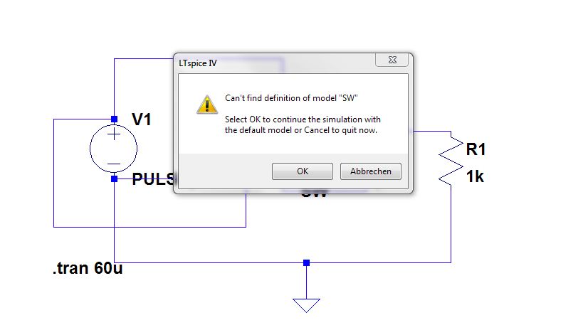
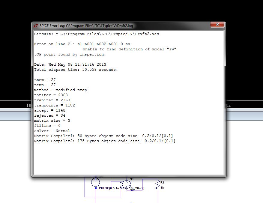
S1 out 0 in 0 MySwitch
.model MySwitch SW(Ron=.1 Roff=1Meg Vt=0 Vh=-.5 Lser=10n Vser=.6)

The voltage between nodes nc+ and nc- controls the switch's impedance
between nodes n1 and n2. A model card is required to define the behavior
of the switch. See the schematic file .\examples\Educational\Vswitch.asc
to see an example of a model card placed directly on a schematic as a
SPICE directive.

Voltage Controlled Switch Model Parameters

Name
 Description
 Units
 Default

Vt
 Threshold voltage
 V
 0.

Vh
 Hysteresis voltage
 V
 0.

Ron
 On resistance
 W
 1.

Roff
 Off resistance
 W
 1/Gmin

Lser
 Series inductance
 H
 0.

Vser
 Series voltage
 V
 0.

Ilimit
 Current limit
 A
 Infin.


The switch has three distinct modes of voltage control, depending on the
value of the hysteresis voltage, Vh. If Vh is zero, the switch is always
completely on or off depending upon whether the input voltage is above
the threshold. If Vh is positive, the switch shows hysteresis, as if it
was controlled by a Schmitt trigger with trip points at Vt - Vh and Vt +
Vh. Note that Vh is half the voltage between trip points which is
different than the common laboratory nomenclature. If Vh is negative,
the switch will smoothly transition between the on and off impedances.
The transition occurs between the control voltages of Vt - Vh and Vt +
Vh. The smooth transition follows a low order polynomial fit to the
logarithm of the switch's conduction.

There is also a level 2 voltage-controlled switch which is an advanced
version of the level 1 switch with negative hysteresis. The level 2
switch is never completely on or off. The conduction as a function of
control voltage Vc is

g(Vc) = exp(A * atan((Vc - Vt)/abs(Vh)) + B)

where

A = log(Roff / Ron) / p
B = log(1 / (Roff * Ron)) / 2

Also, the transition of the level 2 switch to current limit is gradual
instead of abrupt. At a fixed control voltage, the I-V curve is given by
the equation

I(V) = Ilimit * tanh(g(Vc) * V)

where Ilimit defaults to 10 amperes for the level 2 switch.

The level 2 switch supports the option to conduct in only one direction
by either specifying the flag "oneway" or specifying a voltage drop with
parameter Vser. The transition between forward conduction and reverse
open circuit can be specified to be a smooth transition by specifying
the parameter epsilon to be non-zero.