Hallo Leute,

Ich verwende den Atmel XMEGA32A4U Mikrocontroller. Ich versuche den ADC
zu laufen zu bekommen, jedoch will Dieser noch nicht fehlerfrei
funktionieren.

Ich habe den ADC den Input Mode auf Single Ended gestellt und den Gain
auf x1. Ich benutze keine Interruptroutine sondern starte die
Digitalisierung von einem Werte und polle dann das dazugehörige
Interruptflag. Sofern die Digitalisierung abgeschlossen ist lösche ich
das Interruptflag und lese dann den Messwert aus. Demnach benutze ich
keine Eventstruktur und keinen Sweep.

Das Ergebnis soll ein unsigned 12 Bit Wert sein (right adjust).

Hier mein Quellcode:

// Calibration values are stored at production time
// Load the calibration value for 12 Bit resolution from the signature
row
ADCA.CALL = read_calibration_byte(PROD_SIGNATURES_START +
ADCACAL0_offset);
ADCA.CALH = read_calibration_byte(PROD_SIGNATURES_START +
ADCACAL1_offset);

//Clock frequency: 2000,000 kHz
ADCA.PRESCALER = ADC_PRESCALER_DIV16_gc;

// Refere4nce: Set Vref to internal 1.00 V Bandgab
// With effectively 11-bit resolution, this means each LSB
// will represent approximately 0.5mV.
// Temperature reference: Off
ADCA.REFCTRL = ADC_REFSEL_INT1V_gc | (1<<ADC_BANDGAP_bp) |
(0<<ADC_TEMPREF_bp);

// Enable ADC, module A
ADCA.CTRLA = ADC_ENABLE_bm; // 0x01

// Insert a delay to allow the ADC common mode voltage to stabilize
delay_us(2);

// Gain stage impedance mode: High-impedance sources
// Current consumption: Apply no limit to ADC sample rate
// Conversion mode: Unsigned
// Free Running mode: Off (single conversion upon trigger)
// Resolution: Resolution is set to 12-bit, right justified (11-bit
effective in signed mode)
ADCA.CTRLB = (0<<ADC_IMPMODE_bp) | ADC_CURRLIMIT_NO_gc |
(0<<ADC_CONMODE_bp) | (0<<ADC_FREERUN_bp) |ADC_RESOLUTION_12BIT_gc;

// Not implementing Event System so ensure EVCTRL is reading zeros
// AD conversion is started by software
ADCA.EVCTRL = ADC_EVACT_NONE_gc;  // 0x00

// Ensure the ADC complete flag is cleared (by writing a '1' to it)
ADCA.INTFLAGS = ADC_CH3IF_bm | ADC_CH2IF_bm | ADC_CH1IF_bm |
ADC_CH0IF_bm; // 0x0F


// ADC channel 0, 1, 2, 3 gain: 1
// ADC channel 0, 1, 2, 3 input mode: Single-ended positive input signal
ADCA.CH0.CTRL = (0<<ADC_CH_START_bp) | ADC_CH_GAIN_1X_gc |
ADC_CH_INPUTMODE_SINGLEENDED_gc;  // 0x01;

ADCA.CH1.CTRL = (0<<ADC_CH_START_bp) | ADC_CH_GAIN_1X_gc |
ADC_CH_INPUTMODE_SINGLEENDED_gc;  // 0x01;

ADCA.CH2.CTRL = (0<<ADC_CH_START_bp) | ADC_CH_GAIN_1X_gc |
ADC_CH_INPUTMODE_SINGLEENDED_gc;  // 0x01;

ADCA.CH3.CTRL = (0<<ADC_CH_START_bp) | ADC_CH_GAIN_1X_gc |
ADC_CH_INPUTMODE_SINGLEENDED_gc;  // 0x01;


// ADC channel 0 positive input: ADC0 pin
// ADC channel 0 negative input: GND
// ADC channel 1 positive input: ADC1 pin
// ADC channel 1 negative input: GND
// ADC channel 2 positive input: ADC2 pin
// ADC channel 2 negative input: GND
// ADC channel 3 positive input: ADC3 pin
// ADC channel 3 negative input: GND
ADCA.CH0.MUXCTRL = ADC_CH_MUXPOS_PIN0_gc;  // 0x00;
ADCA.CH1.MUXCTRL = ADC_CH_MUXPOS_PIN1_gc;  // 0x10
ADCA.CH2.MUXCTRL = ADC_CH_MUXPOS_PIN2_gc;  // 0x20
ADCA.CH3.MUXCTRL = ADC_CH_MUXPOS_PIN3_gc;  // 0x30


// Channel 0, 1, 2, 3 interrupt: Disabled
ADCA.CH0.INTCTRL = ADC_CH_INTMODE_COMPLETE_gc | ADC_CH_INTLVL_OFF_gc;
// 0x00

ADCA.CH1.INTCTRL = ADC_CH_INTMODE_COMPLETE_gc | ADC_CH_INTLVL_OFF_gc;
// 0x00

ADCA.CH2.INTCTRL = ADC_CH_INTMODE_COMPLETE_gc | ADC_CH_INTLVL_OFF_gc;
// 0x00

ADCA.CH3.INTCTRL = ADC_CH_INTMODE_COMPLETE_gc | ADC_CH_INTLVL_OFF_gc;
// 0x00

void get_adc_sample(unsigned char *new_adc_sample)
{
  PORTD.OUTSET = 0x08;

  ADCA.CH0.MUXCTRL = ADC_CH_MUXPOS_PIN0_gc;
  ADCA.CH1.MUXCTRL = ADC_CH_MUXPOS_PIN1_gc;
  ADCA.CH2.MUXCTRL = ADC_CH_MUXPOS_PIN2_gc;
  ADCA.CH3.MUXCTRL = ADC_CH_MUXPOS_PIN3_gc;

  // Start the AD conversion on channel 0, 1 ,2 ,3
  ADCA.CTRLA |= 0x3C;

  // Wait for the AD conversion to complete
  while ((ADCA.INTFLAGS & 0x0F) == 0);

  // Clear the interrupt flag
  ADCA.INTFLAGS = ADCA.INTFLAGS;

  new_adc_sample[0] = ADCA.CH0.RESH;
  new_adc_sample[1] = ADCA.CH0.RESL;

  new_adc_sample[2] = ADCA.CH1.RESH;
  new_adc_sample[3] = ADCA.CH1.RESL;

  new_adc_sample[4] = ADCA.CH2.RESH;
  new_adc_sample[5] = ADCA.CH2.RESL;

  new_adc_sample[6] = ADCA.CH3.RESH;
  new_adc_sample[7] = ADCA.CH3.RESL;
}


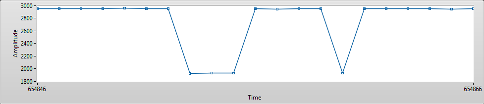
Der ADC läuft auch jedoch erhalte ich sehr häufe große 256 oder 512
Digit Sprünge. Dies kann ich mir nicht erkären. Ich habe die Samplerate
bereits von 2MBit auf ca 65kHz reduziert. Den Low-Impedanz Mode
ausprobiert hat jedoch alles nichts gebracht. Ich habe direkt am
Mikrocontroller Pin mit einem Oscilloscope gemessen. Dort konnte ich
keine Sprünge erkennen. Ich habe bereits auch das Errata durchgelesen
und beim ADC schein alles laut Datenblatt ok zu sein.
Hallo,
vll. liegt es daran, dass du weder etwas zum HW-Aufbau (Schaltplan +
Konkreter Aufbau preisgibt) + den code nichtmal in eine Codebox
geschweige den als Datei anhängt, damit man ihn gescheit lesen kann. Und
keine 90 Minuten warten kann, hier sind keine HA, sondern nur
Freiwillige unterwegs.
Von daher vll. kam noch keiner Dazu sich das anzuschauen.
MfG
ich
Johann schrieb:> Der ADC läuft auch jedoch erhalte ich sehr häufe große 256 oder 512> Digit Sprünge.
Folgt dein Hardwareaufbau den Empfehlungen von Atmel? Ist insbesondere
AVCC von VCC entkoppelt?
> http://www.atmel.com/Images/doc8278.pdf
Hallo Johann,

übe dich bitte in Geduld, auch ich sitze schon gut 45Min an deinem Post!

lies dir bitte auch die Errata zum ADC von Atmel durch, da gibts jede
Menge Einschränkungen/Fehler.

Evtl. versuch mal die Channels einzeln hintereinander zu
aktivieren/abfragen, oder Versuch mal folgendes:
1
ADCA.EVCTRL=ADC_SWEEP_0123_gc;
Ah ja, und das ein ADC Werte liefert heißt nicht das er sauber läuft,
ich spreche aus Erfahrung :D

Gruß, Christoph
Sorry sollte nicht so rüber kommen.

Ich habe mal ein PDF vom Schaltplan drangehängt. Ich weiß ich habe keine
Entstörrdrossel an AVCC gehängt und ich betreiber den XMEGA mit 5V
Johann schrieb:> Ich weiß ich habe keine> Entstörrdrossel an AVCC gehängt und ich betreiber den XMEGA mit 5V
Aber du hast sicherlich schon probiert eine Induktivität an AVCC zu
hängen und VCC auf 3.6V zu reduzieren?
Die Spannung muß runter, anders kommen wir hier zu keiner Lösung.
>• Operating Voltage>– 1.6 – 3.6V
und 4V unter absolut maximum ratings -> 5V geht gar nicht.
Gruß
So habe einen Spannungsregler drauf gemacht. Aus 5V werden jetzt 3,3V
erzeugt. VCC beim USB auf USART Converter habe ich bei 5V gelassen. Der
besitzt einen internen 3,3V Regler um damit VCCIO zu erzeugen. Ich werde
es gleich mal ausprobieren und gebe dann Rückmeldung
Den XMEGA kann ich leider nicht so einfach tauschen. Muss höchstens eine
neue Platine bestücken. Das ist jedoch schon mit viel Arbeit verbunden.
Momentan hoffe ich ja noch das ich einen Firmware Bug habe.

Im Anhang befindet sich ein Screenshot vom Sprung.
Hi Johann,

hab deinen Code nun auf meinem 128A1 laufen. Die Messung schwankt um ca.
+-6 auf einem Steckbrett ohne Filter. Messen tu ich 0,5V erzeugt durch
einen Spannungsteiler.

Ich schätze du hast deinen 32A4 mit den 5V verbraten :D

Die einzigen Änderungen die ich machen musste sind nur GCC-bedingt bzw.
Prozessor-bedingt:
Ich wollte auch selber noch die Messung auf einem älteren Bord
vornehmen. Dort betreibe ich den Xmega auch mit 3,3V und AVCC ist wie
von Atmel empfohlen beschaltet. Jedoch Streit das alte Board noch.
Morgen werde ich ein zweites Board bestücken und die Fehler gleich
beseitigen und es dann noch einmal versuchen.

Aber vielen Dank das du es ausprobiert hast. Bei einigen Spannungsleveln
bekomme ich auch keine Fehler jedoch wenn ich die Eingangsspannung am
ADC Pin veränder dann erhalte ich ab und zu diese Sprünge
Du schaltest einen PORTD beim auslesen, mir fällt grad auf das dieser
gar nicht beschaltet ist. Vieleicht ist der Fehler doch banaler als wir
denken.

Hast du PORTA auf Eingang?

Das fehlte auch in deinem Code...
Setzt doch mal versuchsweise den Prescaler hoch (ADC Clock runter).
Auf meinen älteren A1 und A3 läuft der ADC free-running mit 125 kHz und
4-kanal Sweep ohne Auffälligkeiten (nur die Errata treffen natürlich
zu).
Ich hatte den Prescaler bereits auf 512 gehabt und somit 65kHz
Samplerate erzeugt. Jedoch hatte das keine Verbesserung erzeugt.

@Matthias

das mit dem Sweep ist eine super Sache nur muss ich leider mehr als 4
Kanäle digitalisieren sonst hätte ich dies auch benutzt.
So habe das 2. Bord bestüclt und dabei die Hardwarefehler beseitigt,
jedoch zeigt es die gleichen Eigenschaften. Ich denke das momentan der
Fehler in der PC Empfangssoftware liegt. Das muss ich morgen noch mal
prüfen.
Ne da streut leider nicht ein :-)

Ich habe auf den Pins vom Mikrocontroller bereits mit einem Oscilloscope
gemessen dort sieht alles OK aus keine Sprünge und Störrungen zu
erkennen
Hab den Fehler gefunden:
Du musst das LOW-Byte des ADC zuerst auslesen, danach erst das
HIGH-Byte.

Auszug:
For a read operation, the low-byte of the 16-bit register must be read
before the high-byte. When the low byte register is read by the CPU, the
high byte of the 16-bit register is copied into the temporary register
in the same clock cycle as the low byte is read. When the high-byte is
read, it is then read from the temporary register.
@ Christoph Vogel

vielen Dank für diesen Hinweis. Ich habe den Thread heute aus den Augen
verloren.

Ich bin EUCH wirklich sehr sehr, sehr dankbar. Endlich ist das Problem
gelöst. Ich war wirklich verzweifelt. Die Information das es sich um ein
16Bit Register handelt habe ich überlesen. Ohne Euch hätte ich den
Fehler nicht gefunden. Deshalb noch mal Tausend Dank für die Geduld und
die Hilfe. Ich ware halt schon angefressen und hatte wegen dem ADC
schlecht geschlafen deshalb noch mal sorry für den manchmal nicht so
freundlichen Umgang.