Gast
#4637034
(Ihr könnt auch gern auf Deutsch antworten)

Hello dear Community,

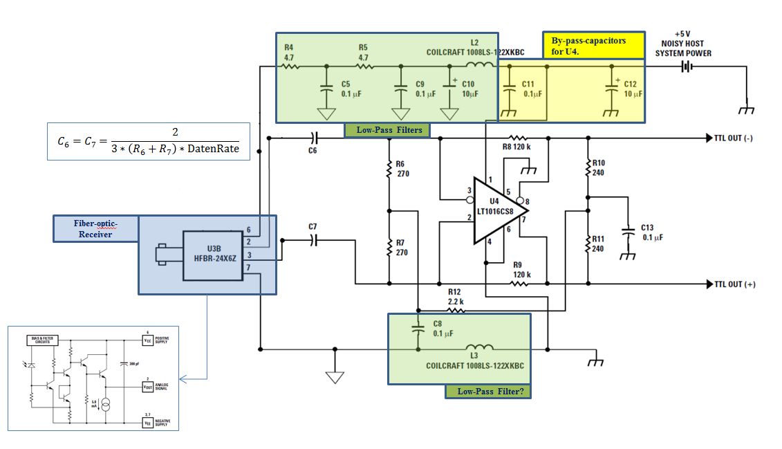
I am trying to analyze the interface circuit between a fiber optic
receiver and a TTL signal.

I have done some work, which you can see in the attachment. Why I still
don't understand is the role of the resistances and capacitances around
the comparator LT1016, although I have read a lot about classical op-amp
and comparator circuit.

I would really appreciate it, if anyone could explain what exact
function each resistance or group of them at input and output has. The
function of the capacitors C6 and C7 is also a mistery to me. In case
classical strategies are used, please mention its name so that I can
read more about it :-)

I have done also a SPICE Simulation of the circuit, taking the receiver
as a voltage source. You can take a look at it, in case this would be
helpful.

In case nodes and current equations need to be solved, you guys don't
need to do it for me. You could give me (precise) indications in what
direction to go.

Thank you very much for your nice and effective help.

Luis

More information on the circuit:

http://www.avagotech.com/docs/AV02-0723EN - Page 6
Angehängte Dateien:
-
 Receiver_Forum.PNG
(100 KB)
Receiver_Forum.PNG
(100 KB)