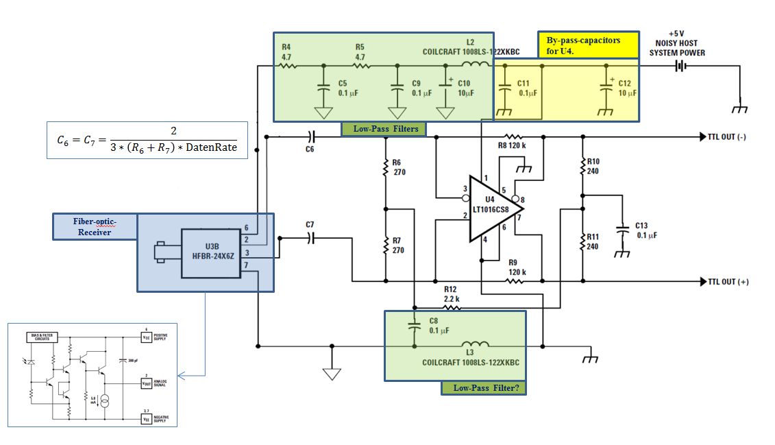
(Ihr könnt auch gern auf Deutsch antworten)

Hello dear Community,

I am trying to analyze the interface circuit between a fiber optic
receiver and a TTL signal.

I have done some work, which you can see in the attachment. Why I still
don't understand is the role of the resistances and capacitances around
the comparator LT1016, although I have read a lot about classical op-amp
and comparator circuit.

I would really appreciate it, if anyone could explain what exact
function each resistance or group of them at input and output has. The
function of the capacitors C6 and C7 is also a mistery to me. In case
classical strategies are used, please mention its name so that I can
read more about it :-)

I have done also a SPICE Simulation of the circuit, taking the receiver
as a voltage source. You can take a look at it, in case this would be
helpful.

In case nodes and current equations need to be solved, you guys don't
need to do it for me. You could give me (precise) indications in what
direction to go.

Thank you very much for your nice and effective help.

Luis

More information on the circuit:

http://www.avagotech.com/docs/AV02-0723EN - Page 6
Angehängte Dateien:
-

Receiver_Forum.PNG
100 KB
Luis S. schrieb:
> Ihr könnt auch gern auf Deutsch antworten

Das meiste davon dient dazu den HFBR mit einer sauberen Betriebsspannung
zu versorgen.
Deshalb gibt es auch zwei GND-Symbole: Die Harke für den mit allerlei
hochfrequenten Störungen verseuchten TTL-GND, und hinter L3 den
gesäuberten Analog-GND, der durch das Dreieck gekennzeichnet ist.
Entsprechendes gibt es auf der +5V Schiene.

Aus dem HFBR kommt schon so viel Signal heraus, dass der LT1016 mit der
verrauschten TTL-Versorgung zufrieden ist.

Der Rest ist trivial:
 Mit dem Spannungsteiler R10 und R11 wird eine +2,5V Spannung *)
bereitgestellt, damit die Eingange des LT1016 arbeiten können, und das
Differenzsignal vom HFBR wird mit C6, C7 kapazitiv zum Komparator
gekoppelt.

R8 und R9 sorgen dort durch ein bischen Mitkopplung für Hysterese.

*) P.S.:
Besser gesagt der Mittelwert zwischen V_OH und V_OL, also etwa  +1,6V
Das was unten "low Pass filter" heisst, ist eigentlich ganz konkret ein
"gnd decoupling" und dient dazu, die virtuelles Masse des Punktes
240/240 biasfrei zub halten.
Vielen Dank Euch für eure Antworten!
Bitte melde dich an um einen Beitrag zu schreiben. Anmeldung ist kostenlos und dauert nur eine Minute.
Bestehender Account
Schon ein Account bei Google/GoogleMail? Keine Anmeldung erforderlich!
Mit Google-Account einloggen
Mit Google-Account einloggen
Noch kein Account? Hier anmelden.