1 | '----------------------------------------------------------------
|
2 | ' (c) 1995-2011, MCS Electronics
|
3 | ' AD_Free_run_1_channel_8-bit_mode + one DMA Channel .bas
|
4 | ' sample written by MAK3
|
5 | '----------------------------------------------------------------
|
6 | ' Using ADC A in differential input mode with 8-Bit over DMA to SRAM
|
7 | ' Configure the ADC of Port A to use 1 Channel with differential Input and with Gain
|
8 | ' Pina 0 (+) and Pina 4 (-) is used for Channel 0
|
9 | ' In this Example we use 8-Bit Mode
|
10 | ' Bit 7 of the Result Byte is the Sign-Bit !
|
11 |
|
12 | $regfile = "xm128a1def.dat"
|
13 | '$regfile = "xm32a4def.dat"
|
14 | $crystal = 32000000 '32MHz
|
15 | $hwstack = 64
|
16 | $swstack = 40
|
17 | $framesize = 40
|
18 |
|
19 | Config Osc = Enabled , 32mhzosc = Enabled
|
20 | Config Sysclock = 32mhz '--> 32MHz
|
21 |
|
22 | 'Serial Interface to PC
|
23 | Config Com3 = 57600 , Mode = Asynchroneous , Parity = None , Stopbits = 1 , Databits = 8
|
24 | Open "COM3:" For Binary As #1
|
25 |
|
26 | Config Dp = Comma 'comma is used as a separator (for FUSING function)
|
27 | 'Config Dp = "." 'dot is used as a separator (for FUSING function). You also need to change this "###.#" in the fusing funtion
|
28 |
|
29 |
|
30 |
|
31 | Print #1 , "----ADC A use DMA Channel 0----"
|
32 |
|
33 | 'For 8 Bit
|
34 | Const Mv_per_adc_step_8_bit = 16.11 'Vref = 3,3Volt/1,6 = 2,0625/128 ADC Steps = 16.11328 mV
|
35 |
|
36 | Const Sample_count = 1000 'Number of samples to aquire
|
37 |
|
38 | Dim Channel_0(sample_count) As Byte 'Measurement Array for Channel 0
|
39 |
|
40 | Dim Milli_volt As Single
|
41 | Dim Channel_0_ready_bit As Bit
|
42 | Dim Channel_0_sample_count As Word
|
43 | Dim X As Word
|
44 | Dim Dma_ready As Bit
|
45 | Dim Dma_channel_0_error As Bit
|
46 |
|
47 |
|
48 | ' DMA Interrupt
|
49 | On Dma_ch0 Dma_ch0_int 'Interrupt will be enabled with Tci = XX in Config DMAX
|
50 | Config Dma = Enabled , Doublebuf = Disabled , Cpm = Ch01rr23 ' enable DMA, Double Buffer disabled
|
51 |
|
52 | 'you can configure 4 DMA channels
|
53 | Config Dmach0 = Enabled , Burstlen = 1 , Chanrpt = Enabled , Tci = Lo , Eil = Lo , Singleshot = Enabled , _
|
54 | Sar = Burst , Sam = Fixed , Dar = None , Dam = Inc , Trigger = &H10 , Btc = Sample_count , Repeat = 1 , Sadr = Varptr(adca_ch0_resl) , Dadr = Varptr(channel_0(1))
|
55 |
|
56 |
|
57 | ' We use DMA Channel 0
|
58 | ' Burstlen = 1 ---> because we use the ADC in 8-Bit Mode
|
59 | ' Channelrepeat is enabled
|
60 | ' TCI = Lo --> Low Level Transaction Complete Interrupt is enabled
|
61 | ' EIL = Lo --> Low Level Error Interrupt is enabled
|
62 |
|
63 | ' Sar = Source Address reloaded after each burst
|
64 | ' Sam = Fixed ---> because we use the ADC in 8-Bit Mode
|
65 |
|
66 | ' Dar = No Destination address reload
|
67 | ' Dam = inc (Destination Address (the Array) will be incremented by one)
|
68 |
|
69 | ' Trigger (Trigger base value for ADC A = &H10 + Trigger offset = &H00 for Channel 0 --> &H10 )
|
70 |
|
71 | ' BTC = sample_count (Block Transfer Count = sample_count number of bytes)
|
72 |
|
73 |
|
74 |
|
75 | '-------------------------------------------------------------------------------
|
76 |
|
77 | Set Adca_ctrla.1 'Flush the ADC Pipeline
|
78 |
|
79 | 'Configure ADC of Port A in FREE running mode
|
80 | 'Enable DMA Channel 0 and DMA Channel 1
|
81 | Config Adca = Free , Convmode = Signed , Resolution = 8bit , Dma = Ch01 , _
|
82 | Reference = Intvcc , Event_mode = None , Prescaler = 128 , Sweep = Ch0 , _
|
83 | Ch0_gain = 1 , Ch0_inp = Diffwgain , Mux0 = &B00000000
|
84 |
|
85 | ' Prescaler = 128 --> 31MHz/128 = 250KHz ADC Clock
|
86 |
|
87 | ' Mux0 = &B00000000 means:
|
88 | ' MUXPOS Bits = 000 --> Pin 0 is positive Input for Channel 0
|
89 | ' MUXNEG Bits = 00 --> Pin 4 is negative Input for Channel 0 (Pin 4 because of Differential with gain)
|
90 |
|
91 |
|
92 | Enable Interrupts
|
93 | Config Priority = Static , Vector = Application , Lo = Enabled
|
94 |
|
95 |
|
96 | '----------------------[Mainloop]-----------------------------------------------
|
97 | Do
|
98 |
|
99 | Loop Until Dma_ready = 1 'Loop until DMA is ready
|
100 | '-------------------------------------------------------------------------------
|
101 |
|
102 | Disable Interrupts
|
103 |
|
104 | Print #1 , Sample_count ; " Sample READY"
|
105 |
|
106 | 'Print Results to COM1
|
107 | For X = 1 To Sample_count
|
108 |
|
109 | ' Print #1 , Channel_0(x).7 ; " / " ; 'print sign Bit in 8-Bit mode = Bit 7
|
110 |
|
111 | If Channel_0(x).7 = 1 Then 'Sign Bit
|
112 | Milli_volt = Channel_0(x) * Mv_per_adc_step_8_bit
|
113 | Milli_volt = Milli_volt - 4096 'Additional calculation in 8-Bit Mode (Bit 7 is Sign Bit)
|
114 | Print #1 , Fusing(milli_volt , "###,#")
|
115 | Else
|
116 | Milli_volt = Channel_0(x) * Mv_per_adc_step_8_bit
|
117 | Print #1 , Fusing(milli_volt , "###,#")
|
118 | End If
|
119 |
|
120 | Waitms 1
|
121 | Next
|
122 |
|
123 |
|
124 |
|
125 | End 'end program
|
126 |
|
127 | '----------------------[Interrupt Service Routines]-----------------------------
|
128 |
|
129 | ' Dma_ch0_int is for DMA Channel ERROR Interrupt A N D for TRANSACTION COMPLETE Interrupt
|
130 | ' Which Interrupt fired must be checked in Interrupt Service Routine
|
131 | Dma_ch0_int:
|
132 |
|
133 | If Dma_intflags.0 = 1 Then 'Channel 0 Transaction Interrupt Flag
|
134 | Set Dma_intflags.0 'Clear the Channel 0 Transaction Complete flag
|
135 | Set Dma_ready
|
136 | End If
|
137 |
|
138 | If Dma_intflags.4 = 1 Then 'Channel 0 ERROR Flag
|
139 | Set Dma_intflags.4 'Clear the flag
|
140 | Set Dma_channel_0_error 'Channel 0 Error
|
141 | End If
|
142 |
|
143 | Return
|

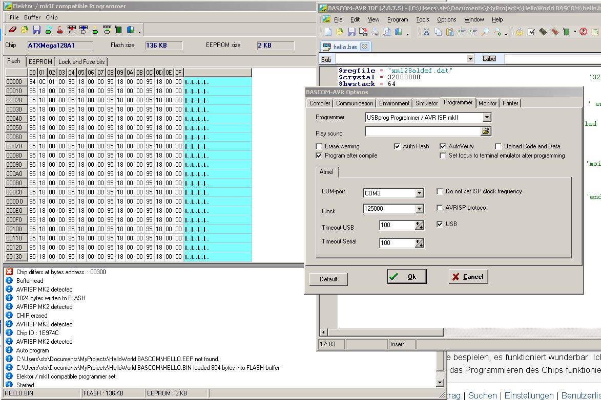
 Bild-Bascom-config.jpg
(220 KB)
Bild-Bascom-config.jpg
(220 KB)
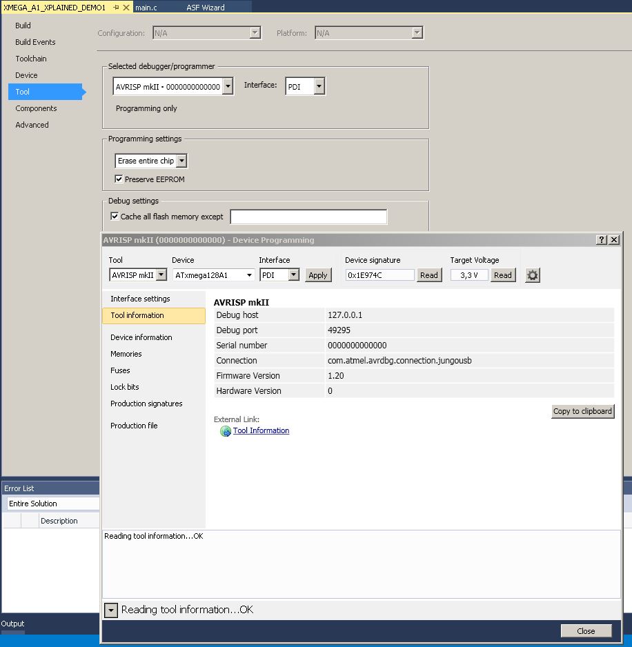
 Bild-AS7-config.jpg
(97 KB)
Bild-AS7-config.jpg
(97 KB)