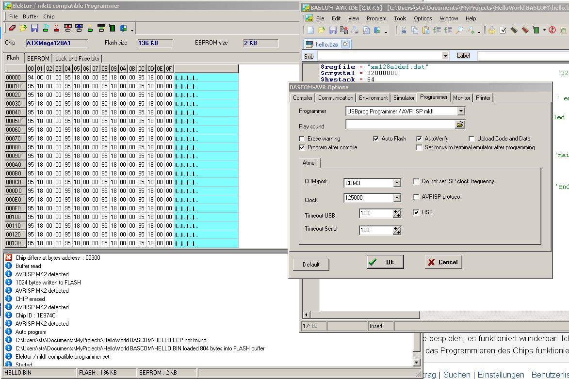
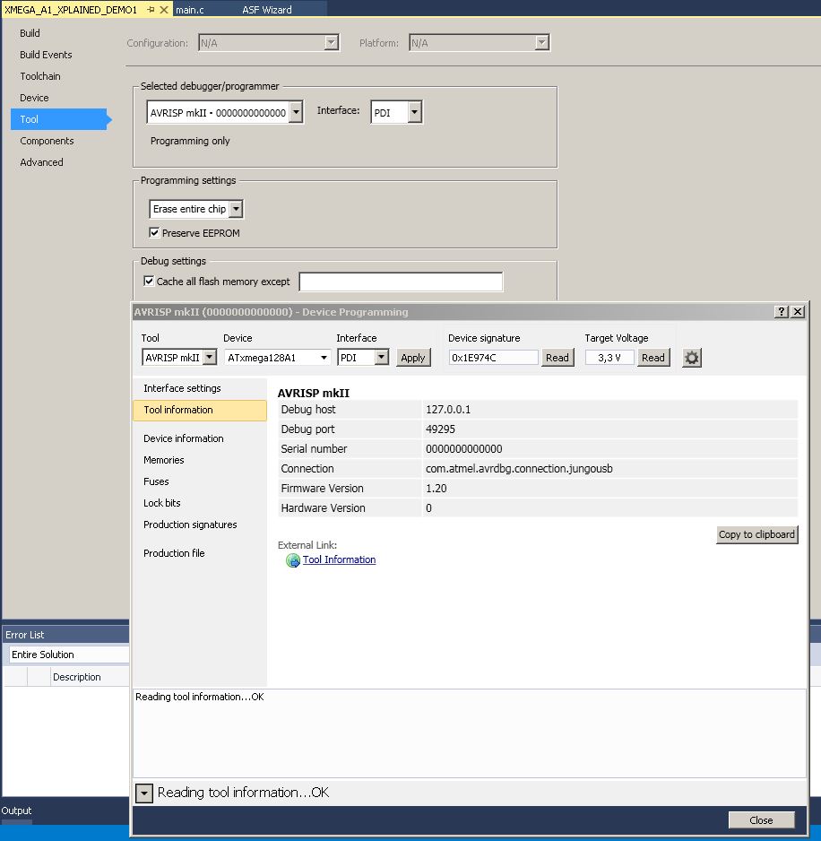
Hallo,

Vor mir liegt ein XMega-A1 XPlained von Atmel und ein "ALL AVR
Programmer" ( http://avr-programmer.com/all-avr/ ). Ich kann das Board
mittels AVR Studio 7 mit meiner Software bespielen, es funktioniert
wunderbar. Im ersten Bild "Bild-AS7-config.jpg" sieht man
Einstellungen im Atmel Studio 7 mit denen das Flashen des Chips
einwandfrei funktioniert.

Leider schaffe ich es nicht mit dem Bascom AVR das Board mit meiner
Software zu bespielen.

Im Bascom-AVR habe ich die in Bild "Bild-Bascom-config.jpg"
dargestellten Einstellungen gemacht (und auch viele andere, z.b. die
Baudrate verändern oder Haken hier und da rausmachen, aber alles ohne
Erfolg).

Ich bekomme nach dem Klick auf "Program Chip" immer die Fehlermeldung
"Chip differs at bytes address : xxxxx". xxxxx ist hierbei manchmal
00300, 00302, ...

Kennt einer dieses Problem mit Bascom-AVR oder kann mir einer sagen, was
hier an meinen Einstellungen falsch sein kann?
Angehängte Dateien:
-

Bild-Bascom-config.jpg
220 KB -

Bild-AS7-config.jpg
97 KB
Angehängte Dateien:
-

Steht_doch_da.jpg
3,8 KB
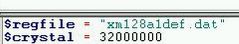
user1x schrieb:
> Bascom erwartet hinter $regfile xm128a1def.dat

Ach?!

..und was steht da? Genau!
Ich habe auch den All AVR Programmer.
Zusätzlich ist bei mir allerdings noch ein Häkchen bei "AVRISP
Protocol".
Probier's halt mal aus.
Angehängte Dateien:
-

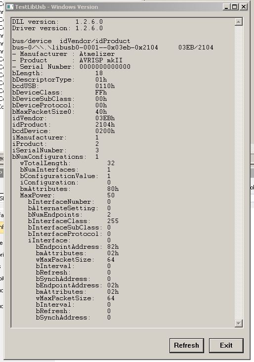
Bild-putty-com3.jpg
220 KB
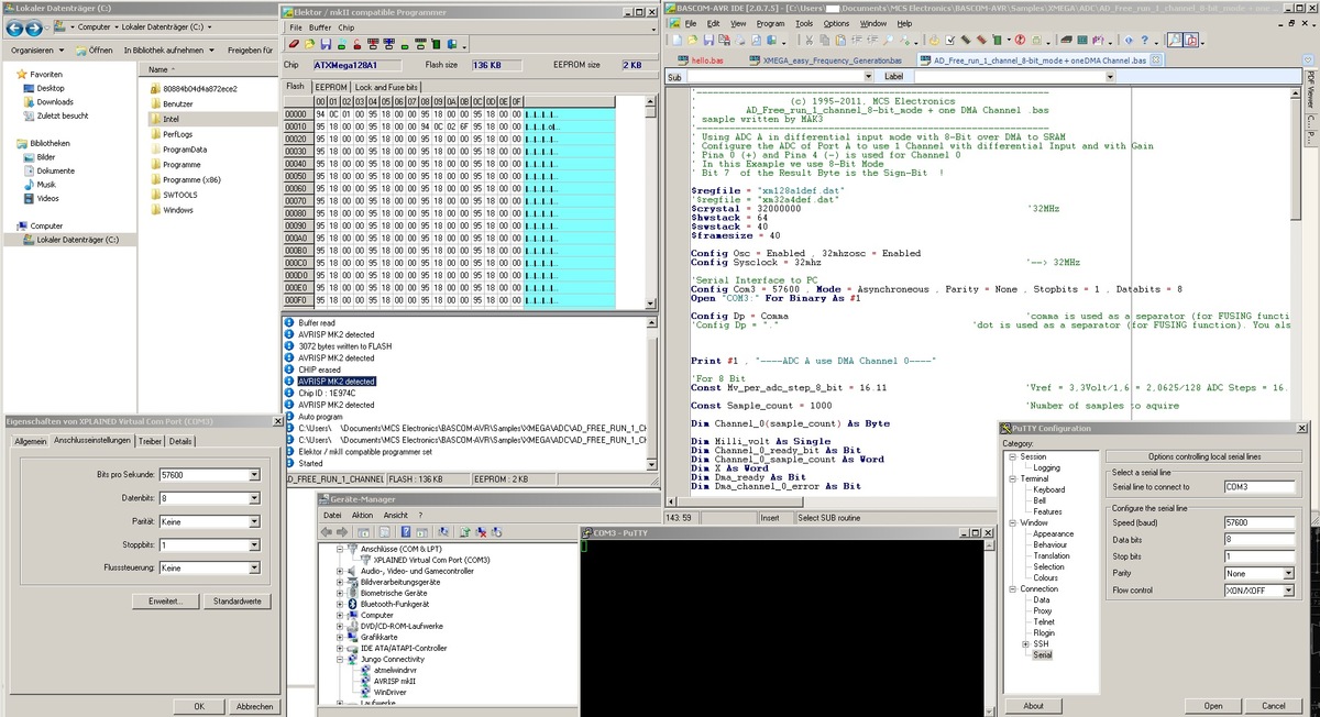
Peter schrieb:
> Ich habe auch den All AVR Programmer.
> Zusätzlich ist bei mir allerdings noch ein Häkchen bei "AVRISP
> Protocol".
> Probier's halt mal aus.

Hi Danke für den Tipp. Der Fehler "Chip differs at byte address: xxx"
tritt nun nicht mehr auf. (Siehe Bild)

Habe noch eine Frage bezüglich COM3 Ausgabe über USB mit Bascom.

Wenn ich meinen XMega-A1 Xplained über seinen eingebauten USB-Anschluss
mit dem PC verbinde, dann kommt im Geräte-Manager ein "XPLAINED Virtual
Com Port (COM3)" dazu.  (auch im Bild enthalten)

Ich möchte nun in meinem Code zum Beispiel über diesen etwas ausgeben.

Dazu habe ich mir ein Bascom-Beispiel-Programm genommen, das dem
Quellcode nach zu urteilen in "COM5" irgendwelche Dinge ausgibt, und
überall wo "COM5" eingetragen war immer "COM3" eingetragen:
1 | '---------------------------------------------------------------- |
2 | ' (c) 1995-2011, MCS Electronics |
3 | ' AD_Free_run_1_channel_8-bit_mode + one DMA Channel .bas |
4 | ' sample written by MAK3 |
5 | '---------------------------------------------------------------- |
6 | ' Using ADC A in differential input mode with 8-Bit over DMA to SRAM |
7 | ' Configure the ADC of Port A to use 1 Channel with differential Input and with Gain |
8 | ' Pina 0 (+) and Pina 4 (-) is used for Channel 0 |
9 | ' In this Example we use 8-Bit Mode |
10 | ' Bit 7 of the Result Byte is the Sign-Bit ! |
11 | |
12 | $regfile = "xm128a1def.dat" |
13 | '$regfile = "xm32a4def.dat" |
14 | $crystal = 32000000 '32MHz |
15 | $hwstack = 64 |
16 | $swstack = 40 |
17 | $framesize = 40 |
18 | |
19 | Config Osc = Enabled , 32mhzosc = Enabled |
20 | Config Sysclock = 32mhz '--> 32MHz |
21 | |
22 | 'Serial Interface to PC |
23 | Config Com3 = 57600 , Mode = Asynchroneous , Parity = None , Stopbits = 1 , Databits = 8 |
24 | Open "COM3:" For Binary As #1 |
25 | |
26 | Config Dp = Comma 'comma is used as a separator (for FUSING function) |
27 | 'Config Dp = "." 'dot is used as a separator (for FUSING function). You also need to change this "###.#" in the fusing funtion |
28 | |
29 | |
30 | |
31 | Print #1 , "----ADC A use DMA Channel 0----" |
32 | |
33 | 'For 8 Bit |
34 | Const Mv_per_adc_step_8_bit = 16.11 'Vref = 3,3Volt/1,6 = 2,0625/128 ADC Steps = 16.11328 mV |
35 | |
36 | Const Sample_count = 1000 'Number of samples to aquire |
37 | |
38 | Dim Channel_0(sample_count) As Byte 'Measurement Array for Channel 0 |
39 | |
40 | Dim Milli_volt As Single |
41 | Dim Channel_0_ready_bit As Bit |
42 | Dim Channel_0_sample_count As Word |
43 | Dim X As Word |
44 | Dim Dma_ready As Bit |
45 | Dim Dma_channel_0_error As Bit |
46 | |
47 | |
48 | ' DMA Interrupt |
49 | On Dma_ch0 Dma_ch0_int 'Interrupt will be enabled with Tci = XX in Config DMAX |
50 | Config Dma = Enabled , Doublebuf = Disabled , Cpm = Ch01rr23 ' enable DMA, Double Buffer disabled |
51 | |
52 | 'you can configure 4 DMA channels |
53 | Config Dmach0 = Enabled , Burstlen = 1 , Chanrpt = Enabled , Tci = Lo , Eil = Lo , Singleshot = Enabled , _ |
54 | Sar = Burst , Sam = Fixed , Dar = None , Dam = Inc , Trigger = &H10 , Btc = Sample_count , Repeat = 1 , Sadr = Varptr(adca_ch0_resl) , Dadr = Varptr(channel_0(1)) |
55 | |
56 | |
57 | ' We use DMA Channel 0 |
58 | ' Burstlen = 1 ---> because we use the ADC in 8-Bit Mode |
59 | ' Channelrepeat is enabled |
60 | ' TCI = Lo --> Low Level Transaction Complete Interrupt is enabled |
61 | ' EIL = Lo --> Low Level Error Interrupt is enabled |
62 | |
63 | ' Sar = Source Address reloaded after each burst |
64 | ' Sam = Fixed ---> because we use the ADC in 8-Bit Mode |
65 | |
66 | ' Dar = No Destination address reload |
67 | ' Dam = inc (Destination Address (the Array) will be incremented by one) |
68 | |
69 | ' Trigger (Trigger base value for ADC A = &H10 + Trigger offset = &H00 for Channel 0 --> &H10 ) |
70 | |
71 | ' BTC = sample_count (Block Transfer Count = sample_count number of bytes) |
72 | |
73 | |
74 | |
75 | '------------------------------------------------------------------------------- |
76 | |
77 | Set Adca_ctrla.1 'Flush the ADC Pipeline |
78 | |
79 | 'Configure ADC of Port A in FREE running mode |
80 | 'Enable DMA Channel 0 and DMA Channel 1 |
81 | Config Adca = Free , Convmode = Signed , Resolution = 8bit , Dma = Ch01 , _ |
82 | Reference = Intvcc , Event_mode = None , Prescaler = 128 , Sweep = Ch0 , _ |
83 | Ch0_gain = 1 , Ch0_inp = Diffwgain , Mux0 = &B00000000 |
84 | |
85 | ' Prescaler = 128 --> 31MHz/128 = 250KHz ADC Clock |
86 | |
87 | ' Mux0 = &B00000000 means: |
88 | ' MUXPOS Bits = 000 --> Pin 0 is positive Input for Channel 0 |
89 | ' MUXNEG Bits = 00 --> Pin 4 is negative Input for Channel 0 (Pin 4 because of Differential with gain) |
90 | |
91 | |
92 | Enable Interrupts |
93 | Config Priority = Static , Vector = Application , Lo = Enabled |
94 | |
95 | |
96 | '----------------------[Mainloop]----------------------------------------------- |
97 | Do |
98 | |
99 | Loop Until Dma_ready = 1 'Loop until DMA is ready |
100 | '------------------------------------------------------------------------------- |
101 | |
102 | Disable Interrupts |
103 | |
104 | Print #1 , Sample_count ; " Sample READY" |
105 | |
106 | 'Print Results to COM1 |
107 | For X = 1 To Sample_count |
108 | |
109 | ' Print #1 , Channel_0(x).7 ; " / " ; 'print sign Bit in 8-Bit mode = Bit 7 |
110 | |
111 | If Channel_0(x).7 = 1 Then 'Sign Bit |
112 | Milli_volt = Channel_0(x) * Mv_per_adc_step_8_bit |
113 | Milli_volt = Milli_volt - 4096 'Additional calculation in 8-Bit Mode (Bit 7 is Sign Bit) |
114 | Print #1 , Fusing(milli_volt , "###,#") |
115 | Else |
116 | Milli_volt = Channel_0(x) * Mv_per_adc_step_8_bit |
117 | Print #1 , Fusing(milli_volt , "###,#") |
118 | End If |
119 | |
120 | Waitms 1 |
121 | Next |
122 | |
123 | |
124 | |
125 | End 'end program |
126 | |
127 | '----------------------[Interrupt Service Routines]----------------------------- |
128 | |
129 | ' Dma_ch0_int is for DMA Channel ERROR Interrupt A N D for TRANSACTION COMPLETE Interrupt |
130 | ' Which Interrupt fired must be checked in Interrupt Service Routine |
131 | Dma_ch0_int: |
132 | |
133 | If Dma_intflags.0 = 1 Then 'Channel 0 Transaction Interrupt Flag |
134 | Set Dma_intflags.0 'Clear the Channel 0 Transaction Complete flag |
135 | Set Dma_ready |
136 | End If |
137 | |
138 | If Dma_intflags.4 = 1 Then 'Channel 0 ERROR Flag |
139 | Set Dma_intflags.4 'Clear the flag |
140 | Set Dma_channel_0_error 'Channel 0 Error |
141 | End If |
142 | |
143 | Return |
Leider sehe ich nun in meinem Putty-Fenster keine Ausgabe. Was habe ich
falsch eingestellt?
Bitte melde dich an um einen Beitrag zu schreiben. Anmeldung ist kostenlos und dauert nur eine Minute.
Bestehender Account
Schon ein Account bei Google/GoogleMail? Keine Anmeldung erforderlich!
Mit Google-Account einloggen
Mit Google-Account einloggen
Noch kein Account? Hier anmelden.