linear operating region to start and maintain oscillation. In order to not exceed the maximum crystal power dissipation, the total power delivered to the crystal must be controlled. The resistor R1 provides this current limiting in the example circuit shown in Figure 1 and has been tuned to ensure that the 1 uW power limit for the ECS-.327-12.5-13 is not exceeded. For a different crystal check the data sheet to ensure that the maximum power dissipation is not exceeded. Capacitors C1 and C2 provide the required
linear operating region to start and maintain oscillation. In order to not exceed the maximum crystal power dissipation, the total power delivered to the crystal must be controlled. The resistor R1 provides this current limiting in the example circuit shown in Figure 1 and has been tuned to ensure that the 1 uW power limit for the ECS-.327-12.5-13 is not exceeded. For a different crystal check the data sheet to ensure that the maximum power dissipation is not exceeded. Capacitors C1 and C2 provide the required
chassis will press too hard on the FPG, and if it is too thin, there will be no thermal flow. Power supplies may be a good source for these pads. They are offen used for cooling the power transistors. On the picture you can see some pads which I found in old power supplies. E buona serata Hayo
a thing. For the serial side connector it would not be difficult while for that in the power supply side would be more complicated without knowing the size. I would risk dangerous short circuits, that isn't good. Buona Domenica. Stefano
stacked with 16MB or 32MB PSRAM in the package, and contains a high-performance (HP) system and a low-power (LP) system; the HP system adopts a RISC-V dual-core processor with a main frequency up to 400MHz, and contains a JPEG encoder/decoder, pixel-processing gas pedal, H.264 video encoder, and a MIPI interface
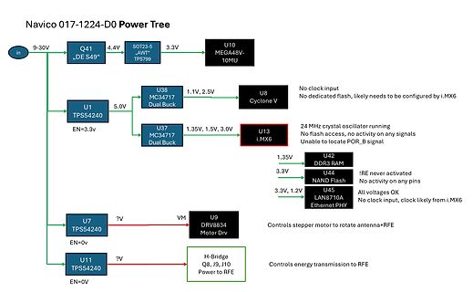
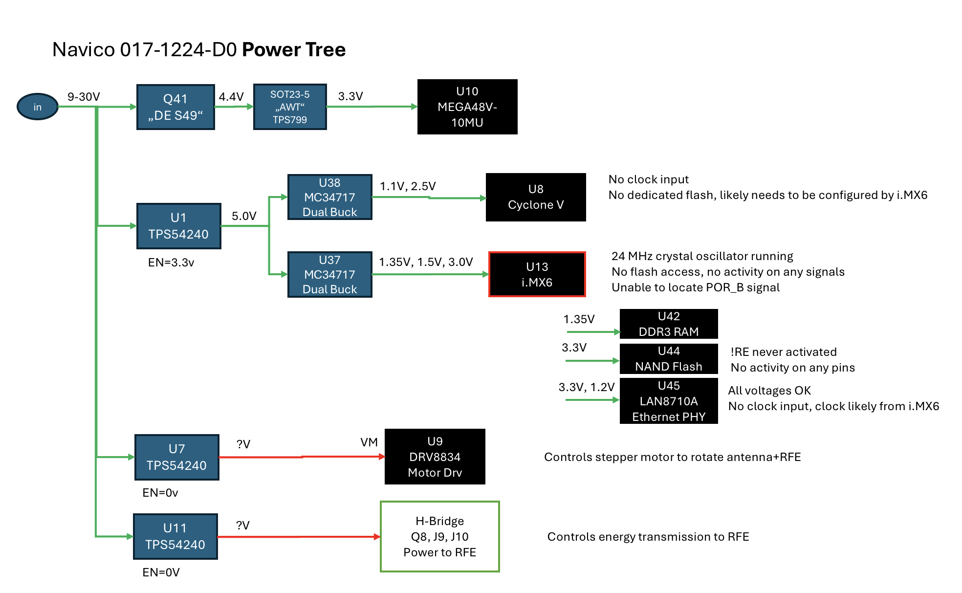
Navico 017-1224-D0 Power Tree
in 9-30V
Q41 DE S49 4.4V SOT23-5 AWT TPS799 3.3V U10 MEGA48V-10MU
U1 TPS54240 5.0V
U38 MC34717 Dual Buck 1.1V, 2.5V U8 Cyclone V No clock input No dedicated flash, likely needs to be configured
Transient Key GWK Groupwise Key HAL Hardware Abstraction Layer IFS Inter Frame Space IP Internet Protocol LAN Local Area Network MAC Media Access Controller MIC Message Integrity Code MPDU MAC Protocol Data Unit MSDU MAC Service Data Unit PA Power Amplifier PCI Peripheral Component Interconnect PS Power Save
arbeitet ein Grafikchip (Substitut für irgendein Prozessor). Für die Konnektivität zum Ethernet soll ein LAN-Controller (MAC und PHY) eingesetzt werden. Wie erfolgt denn eigentlich die Anbindung zwischen der CPU (VGA-Chip) und dem MAC/PHY-Baustein? Ist es bei der Auswahl des MAC/PHYs völlig egal, welchen Typ man nimmt? Worauf muss denn primär geachtet werden (Power management Aspekte mal beiseite gelegt). Danke für Eure Antworten. KK
and longer communication distance than RS-232. Application devices include telecommunication units, LAN, data concentration, data multiplexers, ISDN, POS, industrial controls, etc. Features Connectivity of RS-422 or RS-485 devices and PC through USB port Short Circuit and over-current protection Plug and play and hot-swapping No external power supply is required Supports data transmission at high rates over long distance (4,000 Ft.) Isolation protected Nullifies the effects of ground shifts and noise signals of the voltages on a network
1970-01-01 01:00:56.155 - [56.155] [INFO ] wland_hal: handle_nl_ifname_event():754: No HW found for lan 1970-01-01 01:00:56.517 - [56.517] [ERROR] station_module: sta_module_get_role_state_info():6031: Role '301' is in state 'UNCONFIGURED', no role infos can be collected. 1970-01-01 01:00:56.517 - [56.517
OK grün Blinkt beim Booten einmal und beim SD Karten Zugriff, ist mit GPIO 16 verdrahtet PWR rot PowerOn, ist direkt mit der 3,3V Spannung des RPI verbunden FDX grün FullDuplex, zeigt an, dass am Lan FullDuplex übertragen wird LNK grün Blinkt, ausgeschaltet bei EthernetAktivität 10M gelb 100 Mbit Lan
#4393358: > Datum und Uhrzeit sind ja klar, aber was die weiteren Angaben bedeuten, Eins ist die power up time. Das Andere weiss ich nicht mehr, steht aber im Forum irgendwo. Kannst Du resetten deswegen stimmt die meist nie und auch da ist ein / war Bug drin.
gehackt wurde ? Daten: CPU X86-base SoC Flash 1Mbytes System Memory 16Mbytes SDRAM LAN 10/100Base-TX Auto MDI/MDI-X USB Port 1-USB2.0 high-speed port Reset Button Yes (Load Factory Defaults ) Power Adapter 5V/2A, switching Dimension 73.5(Length) x 63(Width) x 30(Height
Für Ethernet benötigst du eine Ethernet PHY, am einfachsten eine RMII kompatible. Ich habe einen LAN8720 von SMSC dafür verplant. Als Display, eignet sich alles mit einem parallelen Interface. Mit einem LVDS Encoder (75LVDS83) sollten auch Notebook Displays mit LVDS Interface funktionieren. Man
eigentlich nur ein paar passive Bauteile (Widerstände und Kondensatoren; für USB-Host evtl. noch ein Power-Switch wie den TPS2041) und die jeweilige Buchse benötigt. Für USB-OTG noch ein Transceiver, z.B. ISP1301 von NXP. Eine Dekodierung von MP3 in Software würde ich nicht machen, da das schon eine
TEMPERATURE SENSOR INTERNAL V SCRATCHPAD DD HIGH TEMPERATURE TRIGGER, TH LOW TEMPERATURE TRIGGER, TL POWER 8–BIT CRC VDD SUPPLY GENERATOR SENSE 030598 2/27 DS1820 PARASITE POWER V pin, as shown in Figure 3. The advantage to this is DD The block diagram (Figure 1) shows the parasite pow- thatthestrongpull–upisnotrequiredontheI
TEMPERATURE SENSOR INTERNAL V SCRATCHPAD DD HIGH TEMPERATURE TRIGGER, TH LOW TEMPERATURE TRIGGER, TL POWER 8–BIT CRC VDD SUPPLY GENERATOR SENSE 021497 2/27 DS1820 PARASITE POWER V pin, as shown in Figure 3. The advantage to this is DD The block diagram (Figure 1) shows the parasite pow- thatthestrongpull–upisnotrequiredontheI
TEMPERATURE SENSOR INTERNAL V SCRATCHPAD DD HIGH TEMPERATURE TRIGGER, TH LOW TEMPERATURE TRIGGER, TL POWER 8–BIT CRC VDD SUPPLY GENERATOR SENSE 030598 2/27 DS1820 PARASITE POWER V pin, as shown in Figure 3. The advantage to this is DD The block diagram (Figure 1) shows the parasite pow- thatthestrongpull–upisnotrequiredontheI
TEMPERATURE SENSOR INTERNAL V SCRATCHPAD DD HIGH TEMPERATURE TRIGGER, TH LOW TEMPERATURE TRIGGER, TL POWER 8–BIT CRC VDD SUPPLY GENERATOR SENSE 030598 2/27 DS1820 PARASITE POWER V pin, as shown in Figure 3. The advantage to this is DD The block diagram (Figure 1) shows the parasite pow- thatthestrongpull–upisnotrequiredontheI
TEMPERATURE SENSOR INTERNAL V SCRATCHPAD DD HIGH TEMPERATURE TRIGGER, TH LOW TEMPERATURE TRIGGER, TL POWER 8–BIT CRC VDD SUPPLY GENERATOR SENSE 030598 2/27 DS1820 PARASITE POWER V pin, as shown in Figure 3. The advantage to this is DD The block diagram (Figure 1) shows the parasite pow- thatthestrongpull–upisnotrequiredontheI
TEMPERATURE SENSOR INTERNAL V SCRATCHPAD DD HIGH TEMPERATURE TRIGGER, TH LOW TEMPERATURE TRIGGER, TL POWER 8–BIT CRC VDD SUPPLY GENERATOR SENSE 021497 2/27 DS1820 PARASITE POWER V pin, as shown in Figure 3. The advantage to this is DD The block diagram (Figure 1) shows the parasite pow- thatthestrongpull–upisnotrequiredontheI
TEMPERATURE SENSOR INTERNAL V SCRATCHPAD DD HIGH TEMPERATURE TRIGGER, TH LOW TEMPERATURE TRIGGER, TL POWER 8–BIT CRC VDD SUPPLY GENERATOR SENSE 021497 2/27 DS1820 PARASITE POWER V pin, as shown in Figure 3. The advantage to this is DD The block diagram (Figure 1) shows the parasite pow- thatthestrongpull–upisnotrequiredontheI
TEMPERATURE SENSOR INTERNAL V SCRATCHPAD DD HIGH TEMPERATURE TRIGGER, TH LOW TEMPERATURE TRIGGER, TL POWER 8–BIT CRC VDD SUPPLY GENERATOR SENSE 021497 2/27 DS1820 PARASITE POWER V pin, as shown in Figure 3. The advantage to this is DD The block diagram (Figure 1) shows the parasite pow- thatthestrongpull–upisnotrequiredontheI
sonstwas unzuschließen, und als Mod zu benutzen. (Aber man stelle sich mal die Reaktionen auf ner LAN-Party vor. Fettes Grafik-Farbdisplay vorne im Rechner mit Statuswerten und diversem anderem, vielleicht sogar ein TV-Bild oder so. :-) Es soll ja anscheinend kein Problem sein, das Display mit S1D13504
eigentlich kein Problem sein, da vom Display ja keine Signale kommen. Ist ja im Einschaltmoment ohne Power. (Oder habe ich mich in meiner Schaltung so verdacht?) Kommt aber noch ne kleine Änderung rein. Der DRDY-Pin des Epson-Controllers dient bei TFTs als Display-Enable Pin. Werde da wohl noch was umschaltbares
5 4 1 GND Ground. 4 1 2 DQ Data Input/Output pin. Open-drain 1-Wire interface pin. Also provides power to the device when used in parasite power mode (see “Parasite Power” section.) 3 8 3 VDD Optional V DDpin. VDD must be grounded for operation in parasite power mode. *All pins not specified in this
5 4 1 GND Ground. 4 1 2 DQ Data Input/Output pin. Open-drain 1-Wire interface pin. Also provides power to the device when used in parasite power mode (see “Parasite Power” section.) 3 8 3 V DD Optional V DD pin. VDD must be grounded for operation in parasite power mode. *All pins not specified in this
Ersatz für den M328. Und mit dem SAMD51 gibt es auf dem Metro M4 von Adafruit auch deutlich mehr Power als mit dem Due, wenn auch bei weniger Pins (aber das ändert Adafruit gerade mit dem Grand Central M4).
=item23b0efb0cb:g:NP0AAOSw-L5brJdZ:rk:2:pf:1&frcectupt=true Also für rund 8 Euro :-) + 32 Bit Power, Fertige, geprüfte Librarys von ST, eine wohl dokumentierte API....
CATCHER GROUP E VE R BO U Q UE T IN TE R NA TIO NA L C O., LTD . WECATCHTHE Address: 13F-3, No. 8, Lane 280, Sec. 6, Minchuan BEST TECH. FOREVER E. Rd., Nei-Hu 114, Taipei, Taiwa., R.O.C TEL: 886226331253 FAX: 886226312881 PART NO. : MC0802A-SGR FOR MESSRS. : CONTENTS NO. ITEM PAGE 1. COVER 1 2.
Could not find a valid BME280 sensor, check wiring!"); while (1); } // BH1750 myLux.powerOn(); myLux.setContHighRes(); // ADS1115 ads.begin(); pulse_pin(TRIGGER_PIN); // ==> 5 // Sensoren auslesen und in Stromsparmode schicken (wenn erforderlich) sensors_read(
Fritzbox ist übrigens nur die fürs WLAN zuständig, der DHCP läuft auf dem ein Vodafone Modem der via LAN an der FB hängt. [c] uint8_t publishMQTTdata(){ char msg[128]; snprintf(msg,128,"{ \"name\": \"BME280\", \"Temp\" : %.2f, \"Pressure\" : %.4f, \"Humidity\": %.2f, \"vBat\" : %.3f }",BME_Data.temp
angezeigt. Das Programm auf dem ESP8266 ist wie folgt programmiert (Code kopiert und angepasst, meine wLan Daten natürlich anonymisiert): Übergebe auch erstmal nur statische Werte. Wenn das klappt, später dann Sensorwerte. [c] /* * HTTP Client POST Request * Copyright (c) 2018, circuits4you.com
//======================================================================= // Power on setup //======================================================================= void setup() { delay(1000); Serial.begin(115200); WiFi.mode(WIFI_OFF); //Prevents reconnection
nur dazu intern die momentane RAM-Speicheradresse der ADCs zu speichern und einen Interrupt für die LAN-Übertragung von n-Bytes anzustoßen.
unbedingt Hobbyist Metier. Wer sich selber die Tool Chain, Editor und Debugger einrichten kann - More power to you! Jeder soll halt mit dem uC seiner Wahl auf seine Weise glücklich werden. Auch wenn es ein STM32 ist:-) Vielleicht könnte man sich im Forum hier mal einigen sich über die Wahl der uC und
DESCRIPTION 5 1 GND Ground. 4 2 DQ Data Input/Output pin. For 1-Wire operation: Open drain. (See “Parasite Power” section.) 3 3 V Optional V pin. See “Parasite Power” section for details of DD DD connection. VDD must be grounded for operation in parasite power mode. DS18S20Z (8-pin SOIC): All pins not specified
verwendete Energie bei Instruktionen (basierend auf MSP430): http://www.eecs.harvard.edu/emnets/papers/laneEmnets06.pdf Da gehts um Low-Power Compilation! Yalu X. schrieb im Beitrag #1794510: > Bei längeren Idle-Loops wird man sowieso überlegen, ob man nicht besser > > den Controller schlafen legt
university of applied sciences ***** ***** Germany ***** ***** Func: ethernet packet-driver for use with LAN- ***** ***** controller CS8900 from Crystal/Cirrus Logic ***** ***** ***** ***** Keil: Module modified for use with Philips ***** ***** LPC2378 EMAC Ethernet controller ***** ***** ***** ***** für KSZ8001
auf Chip-Ebene geschrupft. In den 70'ern waren das noch große Leiterplatten. Google mal nach "DEC LAN Bridge 100", wenn Du wissen willst, was ich meine. Ethernet hat den großen Vorteil, dass es gleichspannungsfrei ist. Das gilt auch für Single Pair Ethernet. Dadurch bekommst Du eine galvanische Isolation
konkreten Feldbus auszusuchen. Adressierung, Topologie, Durchsatz, Reichweiten, Verkabelungsaufwand, Power over, ... . Am Ende wirst Du ein System mit ausreichendem Datendurchsatz und Entfernung finden. Ganz sicher. Notfalls über Lorawan oder Starlink.
end of Power On Sequence and before receiving Sleep Out command. Also between receiving Sleep In command and Power Off Sequence. Note 4: If RESX line is not held stable by host during Power On Sequence as defined
of Sale equipment Low power consumption: <23mA in Transmit mode 17.0mA in Receive mode User programmable: Frequency o f operation Data Rate Output Power Description The Easy -Radio 400 Transceiver is a complete sub -system that
to the power pins of the transceiver. The use of ‘switch mode’ power supplies should be avoided as they can generate both conducted and radiated high frequency noise that can be very difficult to eliminate. This
N: PVC160101PTN03 VERSION: NEW Page 7 5.0 ELECTRICAL SPECIFICATIONS ITEM SYMBOL MIN TYP MAX UNITS Power-supply V DD 4.7 5.0 5.3 V voltage Power-supply IDD ¡— 1.6 2.5 mA current (VDD=5V ) Vo Vop output voltage ---- 4.5 ----- V V IH 0.8VD D ¡— VDD Input voltage V V IL 0 ¡— 0.2VD D 5.1 POWER SUPPLY CIRCUIT
https://www.digikey.de/de/products/detail/amd/EK-U1-ZCU111-G/9655153 Wer mal etwas mehr Power braucht ;-)
irgendeinen beliebigen USB-NIC-Adapter kaufen kann, denn an den Teensy anstöpsele und ich bin darüber im LAN? Wenn das wirklich so wäre, hätte ich doch einiges verschlafen. Allerdings: ich bin mir doch ziemlich sicher, dass ich nicht *so* lange geschlafen habe... Was die *prinzipielle* Unterstützung
kann man dann auf verschiedene Arten erreichen. Entweder man tastet direkt den RF-Sender über das Power-Management, geeignet für 100% AM-Hub oder man benutzt die umschaltbaren Sendeleistungen über die TX-Konfiguration, geeignet für AM-Hübe zwischen ca. 25% und 85%. Mehr oder weniger "fertigen" Code
Anschlüsse;ginge es evtl dort einen stick anzuklemmen mit nem MC der intertechno Signale sendet,per LAN an deren Gateway oder selber mit RF transmitter? Ziel ist einfaches an/aus schalten per Smartphone im WLAN mit NFC als Auslöser,kein Raspberry oder allround Gateway.eher dann den stick bauen...
Error in initializing ST-LINK device. Reason: [12.294] initServerContext(): Unknown. Please check power and cabling to target. [/code]
Low-Level-Programmierer schrieb im Beitrag #6351070: > Please check power and cabling to target. Genau das hätte ich jetzt auch ohne diese Meldung empfohlen. Hast du Dupont Kabel oder Steckbretter im Aufbau? Die haben oft Wackelkontakte bzw. unsichtbare Kabelbrüche
+ Das Interface: - Webinterface mit HTML, CSS und Javascript -> Auch Steuerung über (W-)Lan/Internet möglich - Mehrere Menüs: Übersicht, Details, Konfiguration - Aufbereitung und grafische Darstellung von Datenbank-Inhalten + Die Wasserkühlung: - Leistungsfähige Doppelkreislauf-Wasserkühlung
Szenarien -> Und alles kombiniert! (Yeah, 3 Jahre programmieren! xD) - Über 10 externe High-Power RGB-Ausgänge auch Zimmerbeleuchtung uvm. steuerbar + LCD-Displays: - RGB-Beleuchtung - Ansteuerung über I²C - Darstellung von Messdaten, Ereignissen, Nachrichten, Datum/Uhrzeit... - Im Seitenteil
Die Dosen sind einzeln an- und ausschaltbar per USB. Neuerdings gibts auch Bluetooth Modelle oder LAN Modelle.
PIC18F67J60 über TCP/IP gesteuert und kann 12 Geräte schalten und zusätzlich 4 Rechner resetten und per Power-Taster an- und ausschalten. Läuft hier seit einigen Jahren 24*7. fchk
so viel Nachteile hat: - Bootzeit - Stromverbrauch - Updates - Zerschießen der SD-Karte bei Power Down - Komplexität Ich bevorzuge eine Startzeit von 1ms bei meinen Applikationen, das fühlt sich sehr angenehm an.
auch immer wieder erstaunt was die M4/M7 so können. Ich habs momentan eher mit Videostreaming( LAN) + USB und so ^^
R22 4. OPERATING INSTRUCTIONS 4.1 Input signal Function NO. Symbol Function 1 VSS Ground (0V) 2 VCC Power supply for Logic circuit 3 V0 Power Supply for Driving the LCD 4 RS Data / Instruction select 5 R/W Read / Write select 6 E Enable signal 7-14 DB0-DB7 Data Bus line 15 LED A Power supply for LED 16 LED K Power supply for LED DATA VISION 03/09/19 11/ 22 SPECIFICATIONSFORLIQUIDCRYSTALDISPLAYMODULE MODELNO:DV-20400-S1FBLY/R22 4.2 Voltage Generator Circuit +5V V CC VCC-V0 V CC LCM V0 VR V ss VCC-V0 : LCD Driving
rmtlmtitdoesnotattackpackageresln. 72 The LED used In the Phobxoupkr genera@ decrcascs t+e light anfssion power by opendim. In case oflong operation time, please design the drcuit with amsldering the de@adaUon of the Qht emissiDn power of the LED. (50%/5yearal 7.3 Pmzautbn fbr Saldaing Photocoupkr Refkrtotheattachcdeheet-I
display with 12 horizontal gris TekVPI probe interface supports active, Standard BNC interface. No power differential, and current without the need provided by the scope, and no 20M record length to capture long time 2M record length only for external power. Probes communicate communication windows

 Bild
Bild