Vybrid Operating Temperature: 0°C … +85°C Dimensions (l x w x h): 80 x 50 x 8 mm Weight: 20 gr. 5.1 Power Power supply: 3.3V +/- 5% Maximum power consumption : 1) 1 A Capacitor charge current on power on: 1.5 A Typical Current Consumption @25°C • Desktop Idle: 290 mA • CPU full load: 370 mA Power supply RTC battery: 2.0 … 3.6 V Power consumption @25°C: typ. 10µA max. 45µA 1) transceiver.value, Summary of max. datasheet value all chips on module w/o SD card, LCD, USB, backplane logic & Power consumption of connected devices like
don't think anyone here can help you. I just play with the hardware and try to unlock all its power. Right now the 1960/1910/1903 are running great with the custom software and VDR. For about 10 - 15 euro you've a great HD capable player.
Infocastserverd, the motorola should now connect to it and get the software. 3) Enjoy the unleased power of the 1960.
car and controller position. The following is a description of the first 5 Bytes. "Mode Bytes" On power up A2 01 02 00 00 is sent (Byte 5 = 00, All controllers enabled even if not plugged in) I propose calling the Mode the unit powers up in, and returns to after a Race is complete and Reset is pressed
with 10 horizontal grids, TekVPI probe interface supports active, Standard BNC interface. No power 100% waveform display with menu-off plus 1/5 of the display is occupied by differential, and current without the need provided by the scope, and no for external power. Probes communicate communication
2.6 V – 4.5 V range. Decoupling capacitors may be used to reduce noise and improve power supply integrity. AC coupling capacitors in 75 nF – 200 nF range must be placed on the MainLink (ML) and AUX lanes. In this particular application the AC coupling capacitors are shown on the connector
Ein paar ordentliche Schaltregler für den Low Power Bereich (ADP3000) oder auch sehr Effiziente (MAX8545). Oder vielleicht auch mal ein paar Präzisions, High-Side, Current-Amplifier (z.B. MAX472CSA). Billige Beschleunigungssensoren wie z.B ADXL213 wären
reinstecken kann, und dann bequemer löten kann i/o warrior von codemercs x-port (aus dem c´t-projekt µc im lan) 1,27mm smd adapter auf 2,54mm wie http://cgi.ebay.de/ws/eBayISAPI.dll?ViewItem&category=8251&item=5718398467 wire-wrap-zubehör mehr maxim-ic´s ic-sockel mit entnahmekeil kleinere wannenstecker
so teuer. Für eine Lösung dazwischen könnte ich mir vorstellen, eine 2. USB-C Buchse rein für Power vorzusehen. Es gibt nämlich folgende interessante entwicklung: https://github.com/hathach/tinyusb/issues/3810 Dann hätte man bei bedarf grundsätzlich über den USB-Host auch die möglichkeit einen
darauf benötigen ja auch Strom. Powerbank wäre auch eine Idee. Ob man USB Aktiv hat oder nur als Power verwendet kann man in der Software herausfinden. Ich weiß es jetzt nicht auswendig auf das Register genau, aber das bekommen wir sicher hin.
utilized 1 1 0 83 - 99% utilized 1 1 1 No service available X X X All other values reserved Table 6: The LAN/Network Access Point Load Factor field The exact loading formula is not standardized. It is up to each LAN/Network Access Point implementation to determine what internal conditions to report as a utilization
the mi- der MicroSD-Karte zu vermeiden, wechseln Sie bitte croSD-card please exchange it always in power-off situa- diese immer im stromlosen Zustand. tions. 4.1.2 Spannungsversorgung 4.1.2 Power supply Der Anschluss einer Spannungsversorgung kann über There are a few possibilities for the power supply
C++, Shell-Script, PHP, Python, wasauchimmer). Und für viele Schnittstellen (SPI, I2C, GPIO, USB, LAN, ...) sind die Treiber bereits im Kernel vorhanden. Dafür braucht es dann nicht mal mehr ein Entwicklungssystem. Oder man entwickelt das auf einem Host mit irgendeinem UNIX (z.B. Linux, macOS), kopiert
Microcontroller Einschränkungen (v.a. in der Zeit bis das System gestartet ist und im perfektionierten Power-Management), aber das spielt nicht immer eine große Rolle. M.E. ist dieser Ansatz oft einfacher, als sich mit der Entwicklungsumgebung des Herstellers herumzuschlagen. Vor allem wenn diese eines Tages
auch kaum Chancen. Und warum kann man nicht mal einen uC "einfach so" programmieren ohne alle 5 Power-Modi zu kennen und ohne 95%e Auslastung des uC? Viele der Arduinos werden so und so nicht an Batterien hängen, da läuft die Kiste halt die ganze Zeit mit Volldampf - na und. Es wird auch ein präemptives
use the kit as a standalone ST-LINK/V2 (with SWD connector for programming and debugging) -Board power supply: through USB bus or from an external 5 V supply voltage -External application power supply: 3 V and 5 V -LIS302DL, ST MEMS motion sensor, 3-axis digital output accelerometer -MP45DT02, ST
Sony Full-HD-Videoprojektor, aktuelles Modell, 3D-fähig, 3000kEur, wird ferngesteuert über: Lan? Neee. Wlan? Neee. Bluetooth? Neee. USB? Auch nich. RS232? Richtig! Nur mal so als Beispiel. Der Laptop muss sich dann halt einen USB-seriell-Wandler verpassen lassen.
sind die 24 zusätlichen bits nicht nur gratis, sondern 32-Bit billiger als Bit. Auch für Ultra-Low-Power Anwender Geckos (falls die größten Kosten in der Stromversorgung anfallen) Für den Hobbiesten auch wichtig: Debugger für STM32 und LPCs (LPCXpresso z.b) werden einem für wenige Euro nachgeworfen
they can be discarded. The Rx filters include a perfect address filter and a hash filter. Wake-on-LAN power management support makes it possible to wake the system up from a power-down state -a state in which some of the clocks are switched off -when wake-up frames are received over the LAN. Wake-up
Headers 5x2 D 12/07/07 1st Demo Board Design 1.0 04/21/10Removed JP3 for EESK strapping option 1.1 LAN1 Reset Add JP3 for connection between VDD_IO and 1.8V RJ45 T (if VDD_IO is 1.8V) KSZ8851SNL Changed the LED pulled up to 3.3V Power Add 4.7K pull up on SO pin +1.8V +2.5V +3.3V C STATUS LEDs Crystal
Ich stand vor einem ähnlichen Problem und habe mich der Einfachheit/Einfallslosigkeit halber an LAN-Adressierung orientiert. Ob das nun die ideale Lösung ist will ich mal offen lassen. CanOPEN war mir schlicht zu kompliziert, ich wollte das in einem Mega8 unterbringen und weder der MCP2515 noch der
Netzwerkmanagement-dienst. Damit werden alle Slave "aktiv" geschaltet. Bedeutet: Nach dem Start (PowerUp) sind alle Slave im sogenannten "pre-operational" mode. sie akzeptieren hier KEINE PDOs! ein umschalten in "operational" erfolgt mit einem NMT. irgendwo in dem Lenze Dok. sollte das ganze als State-Maschine
mal nicht so einen Kopf um die Übertragung. ich habe hier ein 5m Kabel ungeschirmt neben einem Lan-Kabel liegen. Ein Max232 wandelt vor dem Kabel auf 5V um, und auch die Spannungsversorgung liegt parallel. Die Platine schaltet ein Relais auf Kommando vom PC und gibt Bestätigung, obwohl größere Pufferkondensatoren
du könntest ja auch mal freie pins an/abschalten, zb einen bei power on, einen nach den inits, und dann evtl noch einen in der while() schleife toggeln lassen. - dann einfach mal nen LSA/Multimeter dranhalten, und schauen was passiert.. -wenn du schon ein oszi zur
entschuldigen. Das Thema ist buchfüllend. https://public.flux.ai/assets/pdf/guide-to-gnd-fills-and-power-planes.pdf
Dioden kann ich einbauen, das sollte kein Problem sein. Das Kabel ist ca.20cm lang und geschirmtes LAN-Kabel mit dem Schirm an Masse. Wären die Dioden da trotzdem sinnvoll? Ich hab übrigens einige Wochen an dem Design gesessen und versucht, an jeden erdenklichen Fall zu denken. Offenbar hat es einen
Hilfsprg.. 2 Drücken Sie im Menü „Dienstprogramm" E/A. 3 Drücken Sie im Menü „E/A" Konfigurieren. • LAN — Wenn ein DSOXLAN LAN/VGA-Modul installiert ist, können Sie die Softkeys LAN-Einstellungen und LAN zurücksetzen zum Konfigurieren der LAN-Schnittstelle verwenden. Siehe hierzu “Einrichten der LAN-Verbindung
.............................................................21 2 1 Introduction EMW3165 is a low-power embedded Wi-Fi module integrates a wireless LAN MAC/baseband /radio, and a Cortex-M4 microcontroller STM32F411CE that runs a unique "self-hosted" Wi-Fi networking library and software application stack
1 2 3 4 5 6 7 8 9 10 11 External Battery PWR_FLAG +5VP +5V +5V Power Buttons Power Supply Measurement ESP-WROOM-32 MODULE 1 Sense +3.3V 0 E A 7 0 S d R4 A +5V_USB 1 R N 1 n PWR_FLAG R k E e 47k/R0402 R44 7 _ 2 p BUT1 4 T O +3.3V D R47 10k/R0402 FET1 3 D A NA/R0402 N
deiner Anwenudng aufbauen. Also egal ob der Spannungsbereich von 1,8 V bis 5 V geht, oder ein Low-Power System, wo der USB/Seriell Wandler auf dem Arduino stören würde, oder einen sehr genauen Takt (Auf den Arduinos kommen gerne billige Resonatoren zum Einsatz), oder einen sehr exotischen Takt (Die Arduinos
besser" kommt auf Deine Anforderungen an, die wir nicht kennen. Z.B.: - Wenn ich etwas mit RJ45 LAN machen will, bevorzuge ich Raspi & Co. (z.B. Datensammlung im Haus wie Temperaturen, Luftdruck, Stromzähler) - Für einfache Datensammler reicht mir meistens ein ESP8266 mit WLAN und LUA Programmierung
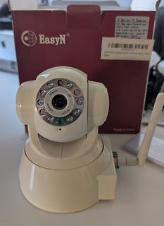
EasyN F-Series IP Cameras User Name: admin Password: admin Adaptor Power: DC5V 1A Internet Access: http://192.168.1.178 IP Address: [unleserlich] DNS Password: 22931K X0002NPHVS EasyN WiFi LAN/WLAN WiFi über das Internet Web New Made in China Vision 3mm IR Night
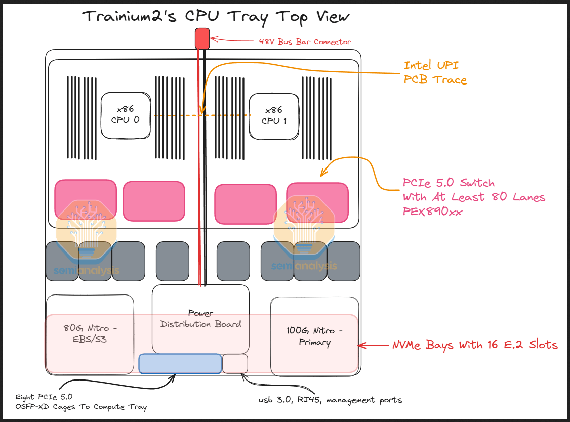
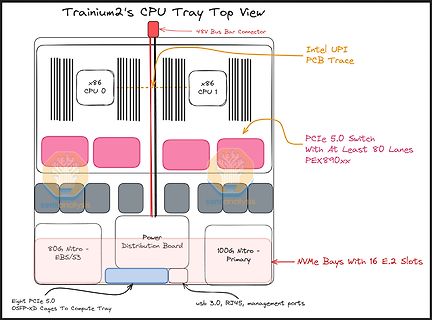
View
48V Bus Bar Connector
Intel UPI PCB Trace
x86 CPU 0
x86 CPU 1
PCIe 5.0 Switch With At Least 80 Lanes PEX890xx
80G, Nitro - EBS/S3
Power Distribution Board
100G, Nitro - Primary
NVMe Bays With 16 E.2 Slots
Eight PCIe 5.0 OSFP-XD Cages To Compute Tray
usb 3.0, RJ45, management ports
lower. * Calculated figures www.ezurio.com 5. DC Characteristics 5.1 RF Performance 5.1.1 Transmit Power Conducted Transmit Power min: 1.0mW (0dBm) max: 4mW (6dBm) Antenna Gain +2dBi typ. Effective Transmit Power min:0dBm Max: +6dBm Output power can be reduced by program control 5.1.2 Receive Sensitivity
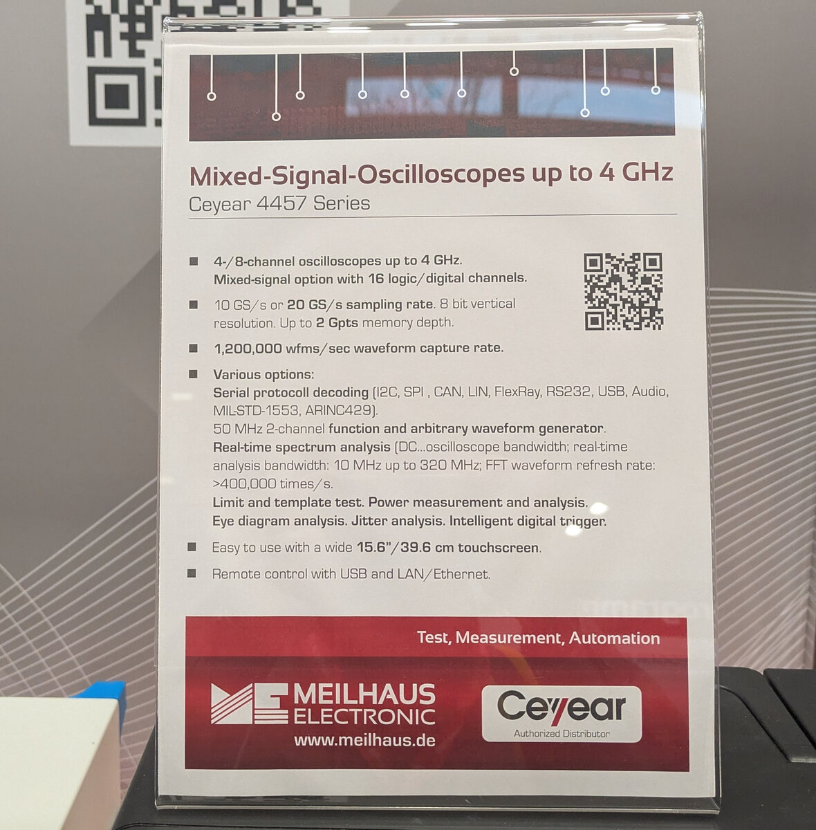
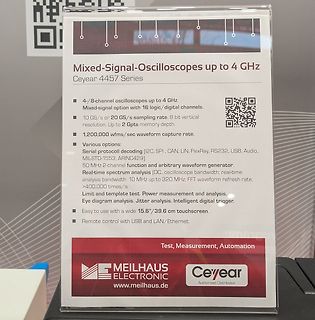
bandwidth: 10 MHz up to 320 MHz; FFT waveform refresh rate: >400,000 times/s).
Limit and template test. Power measurement and analysis. Eye diagram analysis. Intelligent digital trigger.
Easy to use with a wide 15.6"/39.6 cm touchscreen.
Remote control with USB and LAN/Ethernet.
MEILHAUS ELECTRONIC
www.meilhaus.de
to work with these switching regulators. Output transistor protected by current limit, under F The power switch is a 3.0A NPN device that can stand-off voltage lockout, and thermal shutdown y 65V. Protecting the power switch are current and thermaln System Output Voltage Tolerance of4% max over line b
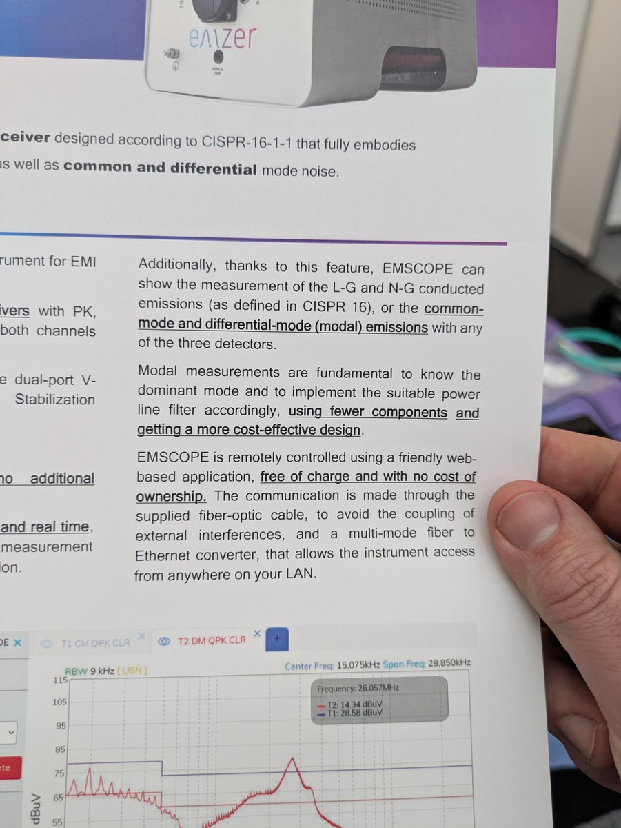
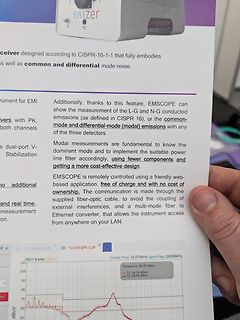
detectors.
Modal measurements are fundamental to know the dominant mode and to implement the suitable power line filter accordingly, using fewer components and getting a more cost-effective design.
EMSCOPE is remotely controlled using a friendly web-based application, free of charge and with no cost of
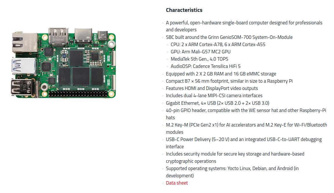
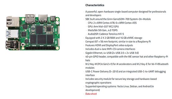
footprint, similar in size to a Raspberry Pi
Features HDMI and DisplayPort video outputs
Includes dual 4-lane MIPI-CSI camera interfaces
Gigabit Ethernet, 4x USB (2x USB 2.0 + 2x USB 3.0)
40-pin GPIO header, compatible with the WE sensor hat and other Raspberry-Pi hats
M.2 Key-M (PCIe Gen2 x1) for AI accelerators and M.2 Key-E for Wi-Fi/Bluetooth modules
USB-C Power Delivery (5–20 V) and an integrated USB-C-to-UART debugging interface
Includes security module for secure key storage and hardware-based cryptographic operations
Supported operating systems: Yocto
OM 0 2 H +5 1 6 3.0 0.3 Unit : mm 10.0 Tolerance :0.5mm FREQUENCY CHARACTERISTICS dB 100 90 80 70 POWER INPUT : 1.5 V, 1/2 DUTY 60 SQUARE WAVE. 50 500 1K 2K 5K 10KHz DISTANCE FOR MEASUREMENT : 10 cm 991129 NO 36, LANE 19, BAH DER ROAD, HSIN CHU, TAIWAN R. O. C. HYCOM DEVICE MANUFACTURING CO., LTD. ဏ˻
USB Interface • Compatible with ISO 10605 (ESD): 330pF/2kΩ, ±20kV Contact • 350 Watts Peak Pulse Power per Line (tp = 8/20µs) • Replacement for MLV (0805) • Unidirectional & Bidirectional Configuration • Protects One Power or I/O Port • ESD Protection > 25kV • Low Clamping Voltage • Available in Multiple
drive ■ Logic High Input, Any Voltage .............2.4V to V DD voltage margin, especially during power up/power down ■ Low Supply Current With Logic "1" Input ... 450 µA sequencing. Propagational delay time is only 55nsec (typ.) ■ Low Output Impedance ....................................Ω2.5 and the
Hallo Guido, wenn Du statt des separaten Übertragers für das LAN einen RJ-45 Connector mit intergriertem Übertrager vorsehen würdest, würde dass einiges an Platz sparen und auch nicht viel mehr kosten. Ausserdem gibt es die RJ-45 Buchsen auch mit integrierten LED
nicht verbunden. /RESET kannst Du ja mit dem Reset des M128 verbinden. Der Dataflash hat zwar einen Power On Reset, aber man will ja definierte Zustände haben, wenn man aufs Reset-Knöpfchen drückt. BUSY kann man auch einsparen, da man dieses Signal auch per Software über SPI abfragen kann. Grüße Andreas
Releaby PARALIGHTDCC PARA LIGHT ELECTRONICS CO., LTD. 4F, No.1, Lane 93, Chien Yi Road, Chung Ho City, Taipei, Taiwan, Tel: 886-2-2225-3733 Fax: 886-2-2225-4800 E-mail: para@para.com.twhttp://www.para.com.tw DATA SHEET PART NO. : C-4001SR-5 REV : A / 0 CUSTOMER’S APPROVAL
it shipping included? Is there a possibility to purchase a Vinculum VNC2 USB-Host also? And the power supply shield? Please, let me know, I guess it is very interesting also for many other people. Thank in advance. Mit Freundlichen Grüßen, Luc
I do not know if it was a case or not, but could spikes really be caused by noise coming from the power supply? Mit Freundlichen Grüßen, Luc
STM32F103 Man braucht nur ein paar Umbenennungen: [c] /* Umdefinitionen NXP-->ST */ #define MCI_POWER SDIO_POWER #define MCI_STATUS SDIO_STA #define MCI_COMMAND SDIO_CMD #define MCI_CLEAR SDIO_ICR #define MCI_ARGUMENT SDIO_ARG #define MCI_RESP0 SDIO_RESP1 #define MCI_RESP1
einem STM32 Midrange-ARM vor. Damit erhälte ich dann komfortable Lösungen direkt mit Datenbank und LAN-Anbindung. Einziges Manko ist die Echtzeitfähigkeit der Standard-Distributionen, aber dafür gibt es ja 4 Kerne mit echter Leistungsfähigkeit.
dB min., insertion loss of 0.8 dB max., and V.SWR of 1.7 max. at 26.5 GHz (50 Ω ). ■ Contact carry power of 120 W at 3 GHz. ■ High sensitivity with rated power consumption of 700 mW for failsafe models and 500 mW for dou- ble-winding latching models. ■ Models with TTL-driven double-winding latching and
pin deactivates the output and reduces supply current to The power ground pin is the ground path for the high 0.01µA. MIC23150 features built-in soft-start circuitry current in PWM mode. The current loop for the power that reduces in-rush current and prevents the
/*********************************Programmbeschreibung*************************** * Name: Lan_Tester.c * * Zweck: Software für die MAin Unit. Controller AT90S2313 * I2C über Port B SDA = PINB0, SCL = PINB1 * Rotary Encoderan PORTD PINS 2,3 * Start Button an PORTD PIN 4 * * erstellt von: Stephan
Powerplane w • Für 0.1 < w/h < 2.0, 1 < εr< 15 t und oberhalb der Leiterbahn Luft h ε R ground or power plane 87Ω 5.98 h Z 0≈ ⋅ln0.8 w + t εr+ 1.41 • Beispiel: øh=0.4mm, w=0.7mm, t=0.035mm, e =4.5 r øZ =050W 20 Fachstelle Elektronik Hochschule Technik+Architektur Luzern HighSpeed PCB.PPT / AK / 23.03.99
TSic™ 206/203/201/306/303/301 Einfach integrierbarer, low power Temperatursensor IC Das Produkt • Speisespannung: V+ = 3.0V bis 5.5V, hoch- genauer Betrieb im Bereich V+ = 4.5V bis 5.5V • Gehäuse: 8-pin SOP-8, 3-pin TO92 (weitere Die TSicTM Serie wurde speziell
Temperature T stg -40 ~ +105 Reflow Temperature *2 T ref 260 ℃ Electrostatic Discharge ESD 150 V Power Dissipation Pd 110 mW Reverse Voltage V R 5 V Notes: *1:IFPonditions--Pulse Width≦10msec and Duty≦1/10. **2:Reflow time≦5 seconds. Everlight Electronics Co., Ltd. http://www.everlight.com Rev. 3 Page
further information on the user option bytes, refer to Section 3: Embedded Flash memory (FLASH). 6.1.2 Power reset A power reset is generated when one of the following events occurs: 1. Power-on/power-down reset (POR/PDR reset) or brownout (BOR) reset 2. When exiting the Standby mode A power reset sets all

 Bild
Bild
 Bild
Bild
 Bild
Bild
 Bild
Bild
 Bild
Bild
 Bild
Bild
 Bild
Bild