Suchergebnisse für "L128"
RP2350A, 12-MHz-Quarz, Kernregler 1,1 V, Reset, 4-MB-Flash, Entkopplung display Blatt 3 Display EA DOGL128 L -6 (128 x 64, SPI) mit den Kondensatoren der Spannungserzeugung leds Blatt 4 LED-Treiber und LEDs LED-Treiber IS31FL3236 (I2C) und 27 Tasten-LEDs D D tasten Blatt 5 Tasten und Drehgeber Tastenmatrix
in
„Review erbeten: Synthesizer mit RP2350, 2× AAA, ohne USB Erstentwurf, kein Elektronikhintergrund“
·
Platinen
·
24.10.2026 18:30
d,x[f+1]=i*p+x[f+1]*d,x[f+2]=s*p+x[f+2]*d,x[f+3]=Math.max(x[f+3],c)}}clear(t,r,l ){const i=this.data;for(let s=0;s<i.length;s+=4)i[s]=t,i[s+1]=r,i[s+2]=l ,i[s+3]=255}}const ue=[{r:255,g:255,b:255},{r:0,g:0,b:0},{r:0,g:0,b:255},{r:0,g:192,b:0},{r:128 ,g:128 ,b:0},{r:255,g:0,b:0},{r:255
in
„KE5FX-Tools unter Linux / Ubuntu / Wine klemmen nach OS-Update“
·
PC Hard- und Software
·
06.11.2026 22:49
1 2 3 4 5 6 7 8 9 10 11 12 13 14 15 16 17 18 19 20 21 22 23 L O L _ W U R S A E _ N W E N _ V H E _ _ _ B D S BT1A Q1 A Q2 N Q3 T R1T R2V R3H R4H R50 R6D U1 L 1T C1T C2T C3 C4 R7 R8O R9T R10T B B O A A N T T I L A A A V V V _ A A V V C L V C L L G H V V V + + +
in
„Review erbeten: Synthesizer mit RP2350, 2× AAA, ohne USB Erstentwurf, kein Elektronikhintergrund“
·
Platinen
·
24.10.2026 14:49
V325"/> <path d="M235 512 H730"/> <path d="M90 390 H850"/> <path d="M110 95 H790"/> <path d="M35 175 L 118 94"/> <path d="M400 95 L 525 207 H815"/> <path d="M790 95 L 873 180 V354 L 850 390"/> <path d="M40 327 L 90 390 L 235 512"/> <path d="M730 512 L 850 390"/> </g> <g class="rail"> <path d="M40 175 V325"/> <path d="M235 512 H730"/> <path d="M90 390 H850"/> <path d="M110 95 H790"/> <path d="M35 175 L 118 94"/> <path d="M400 95 L 525 207 H815"/> <path d="M790 95 L 873 180 V354 L 850 390"/> <path d="M40 327 L 90 390 L 235 512"/> <path d="M730 512 L 850 390"/> </g> <!-- Kleine Farbpunkte: Durchmesser 6 SVG-Einheiten
in
„Ki Hilft.wenn auch nicht immer“
·
Offtopic
·
28.10.2026 22:58
V325"/> <path d="M235 512 H730"/> <path d="M90 390 H850"/> <path d="M110 95 H790"/> <path d="M35 175 L 118 94"/> <path d="M400 95 L 525 207 H815"/> <path d="M790 95 L 873 180 V354 L 850 390"/> <path d="M40 327 L 90 390 L 235 512"/> <path d="M730 512 L 850 390"/> </g> <g class="rail"> <path d="M40 175 V325"/> <path d="M235 512 H730"/> <path d="M90 390 H850"/> <path d="M110 95 H790"/> <path d="M35 175 L 118 94"/> <path d="M400 95 L 525 207 H815"/> <path d="M790 95 L 873 180 V354 L 850 390"/> <path d="M40 327 L 90 390 L 235 512"/> <path d="M730 512 L 850 390"/> </g> <!-- Farbige Gleisüberlagerungen --> <g id
in
„Ki Hilft.wenn auch nicht immer“
·
Offtopic
·
30.10.2026 18:47
Bild
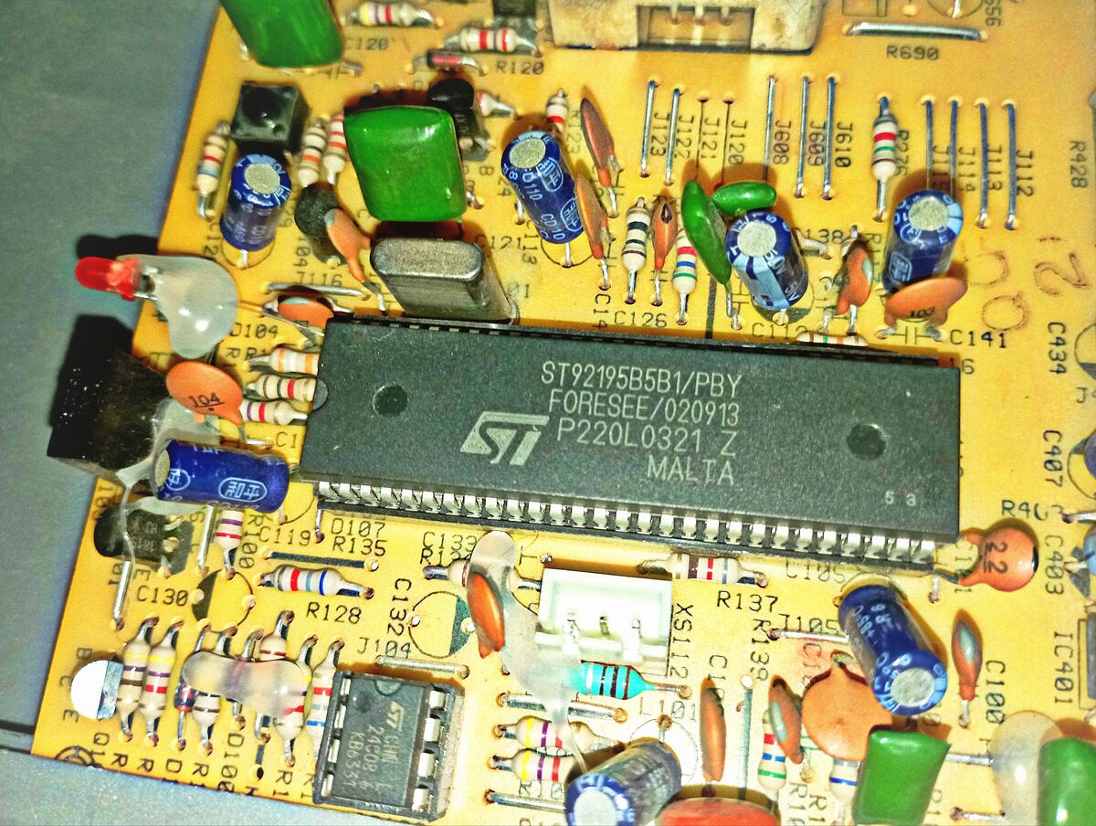
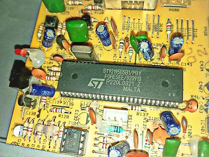
ST92195B5B1/PBY FORESEE/020913 ST P220L 0321 Z MALTA R690 R120 J122 J121 J120 J608 J610 R27 J112 J113 J119 J112 C141 C439 C407 C403 R463 R467 C100 IC401 R137 C105 C139 R138 C132 R128 C130 C119 R135 D107 D104 C1 C126 C121 J104
in
„Schrittweise Reparatur eines alten 14-Zoll-Röhrenfernsehers – zunächst sichtbare Defekte beseitigen.“
·
Analoge Elektronik und Schaltungstechnik
·
09.11.2026 18:37
·
Platinenfotos
Bild
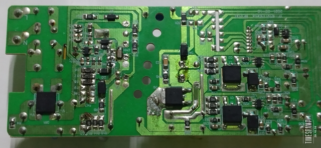
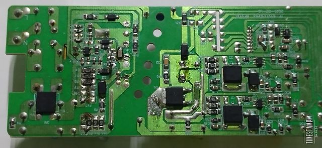
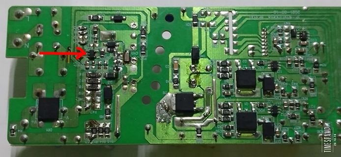
L , N, C101, C102, C103, C104, C105, C106, C107, C108, C109, C110, C111, C112, C113, C114, C115, C116, C117, C118, C119, C120, C121, C122, C123, C124, C125, C126, C127, C128 , C129, C130, C131, C132, C133
in
„Schaltnetzteil aus LED Deckenleuchte“
·
Analoge Elektronik und Schaltungstechnik
·
20.10.2026 21:23
·
Platinenfotos
Bild
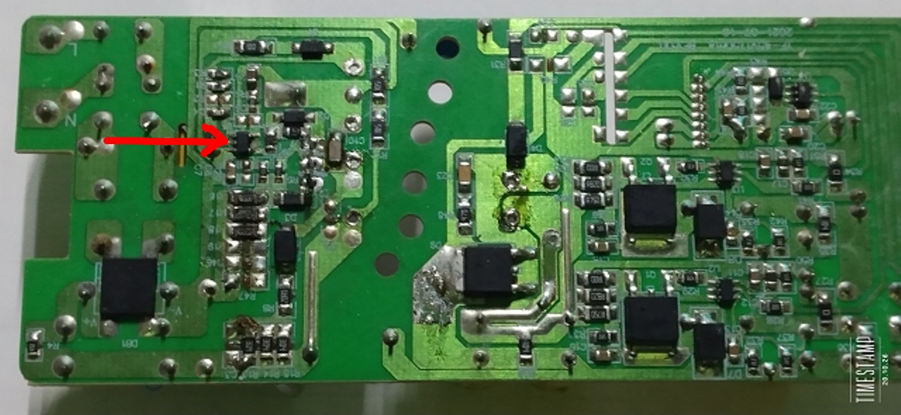
L , N, C10, C11, R47, R58, R59, R60, R61, R62, R63, R64, R65, R67, R72, R73, R74, R75, R76, R77, R78, R79, R80, R81, R82, R83, R84, R85, R86, R87, R88, R89, R90, R91, R92, R93, R94, R95, R96, R97, R98,
in
„Schaltnetzteil aus LED Deckenleuchte“
·
Analoge Elektronik und Schaltungstechnik
·
20.10.2026 21:32
·
Platinenfotos
Bild
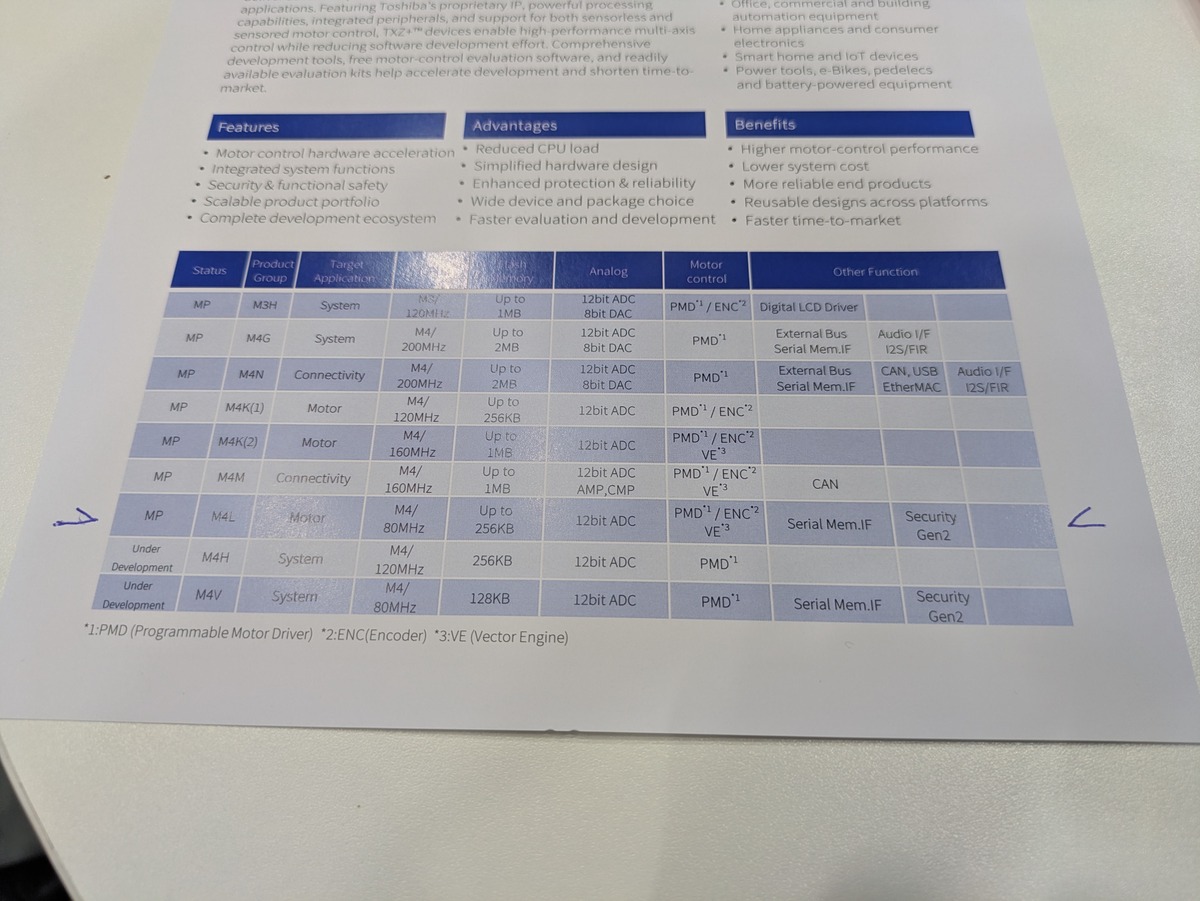
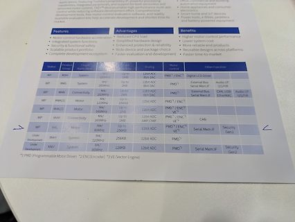
to 1MB 12bit PMD1/ENC2 VE3
MP M4N Connectivity M4/160MHz Up to 1MB 12bit 8bit DAC AMP,CMP CAN
MP M4L Motor M4/80MHz Up to 256KB 12bit PMD1/ENC2 VE3 Serial Mem.IF Security Gen2
Under Development M4H System M4/120MHz 256KB 12bit ADC PMD1 Serial Mem.IF Security Gen2
Under Development M4V System M4/80MHz 128 KB 12bit ADC VE3
in
„Electronica 2026, Tag 3 – aktive Komponenten“
·
Mikrocontroller und Digitale Elektronik
·
14.11.2026 16:21
·
Fotos
Bild
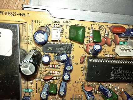
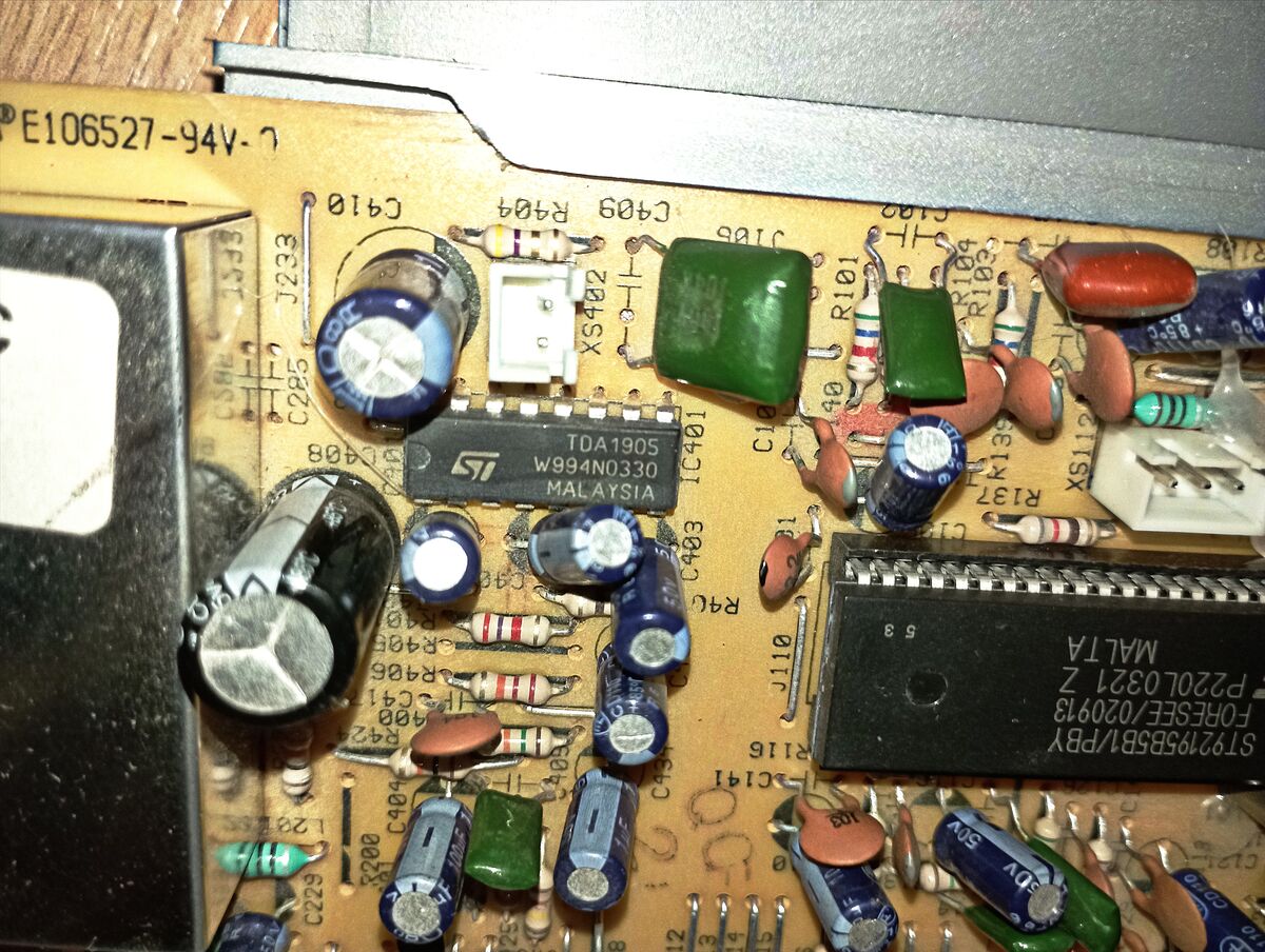
E106527-94-L J233 C285 C410 R404 C409 R40 R101 R104 R103 XS402 TDA1905 ST IC401 MALAYSIA C408 C403 C406 R405 R406 R407 R408 R409 R410 C411 C412 R413 C414 J110 R116 C415 C416 R117 C417 C418 R118 C419 C420 R119 C421
in
„Schrittweise Reparatur eines alten 14-Zoll-Röhrenfernsehers – zunächst sichtbare Defekte beseitigen.“
·
Analoge Elektronik und Schaltungstechnik
·
09.11.2026 18:51
·
Platinenfotos
avr/io.h> #include <avr/interrupt.h> #include <stdlib.h> #define BIT(x) (1<<x) #define F_CPU 16000000L // 16MHz ggf. an eff.Frequenz anpassen #define T1_VORTEILER 8 #define PRO_SEKUNDE 100 // alle 10 ms #define OCR1A_TEILER (F_CPU / T1_VORTEILER / PRO_SEKUNDE) #define ADC_SCHRITTE 1024 // bei 10 Bit #
in
„Ich möchte aus einer Spannung einen binärcode erzeugen“
·
Analoge Elektronik und Schaltungstechnik
·
18.10.2026 12:48

 Bild
 Bild
 Bild
 Bild
 Bild