-
 Bild
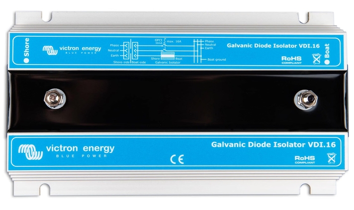
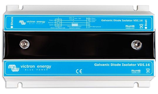
Victron Energy Galvanic Diode Isolator VDI.16
victron energy BLUE POWER Phase Neutral Earth Shore-side Shore Galvanic Isolator max. 16A 30mA Boat Galvanic Isolator Boat ground Phase Neutral Earth Boat Galvanic Diode Isolator VDI.16 RoHS COMPLIANT CE
-
Thread
Historische Bauteile?
in Korea gefertigt wurden. s4008-9.jpeg Bauform: Es sind hochwertige 24-Pin-Keramikgehäuse (Side-brazed CDIP) mit vergoldeten Anschlussbeinchen und einem goldenen Deckel. Diese Bauweise war in den 1970er-Jahren üblich für frühe Mikroprozessor- und Speicherbausteine sowie für Industrieelektronik
-
 Bild
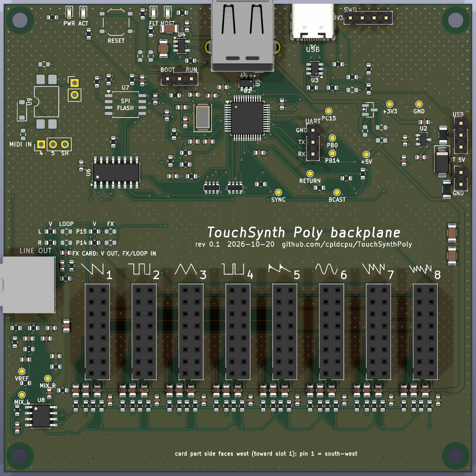
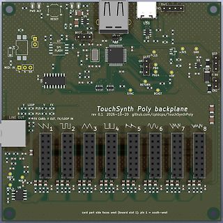
PCB-Layout der TouchSynth Poly Backplane
MIDI IN 4 5 SH USB SWD EV3 +3V3 GND U2 +5V T 5V GND 1 2 3 4 5 6 7 8 V REF MIX_R MIX_L U8 card part side faces west (toward slot 1): pin 1 = south-west TouchSynth Poly backplane rev 0.1 2026-10-20 github.com/cpldcpu/TouchSynthPoly
-
 Bild
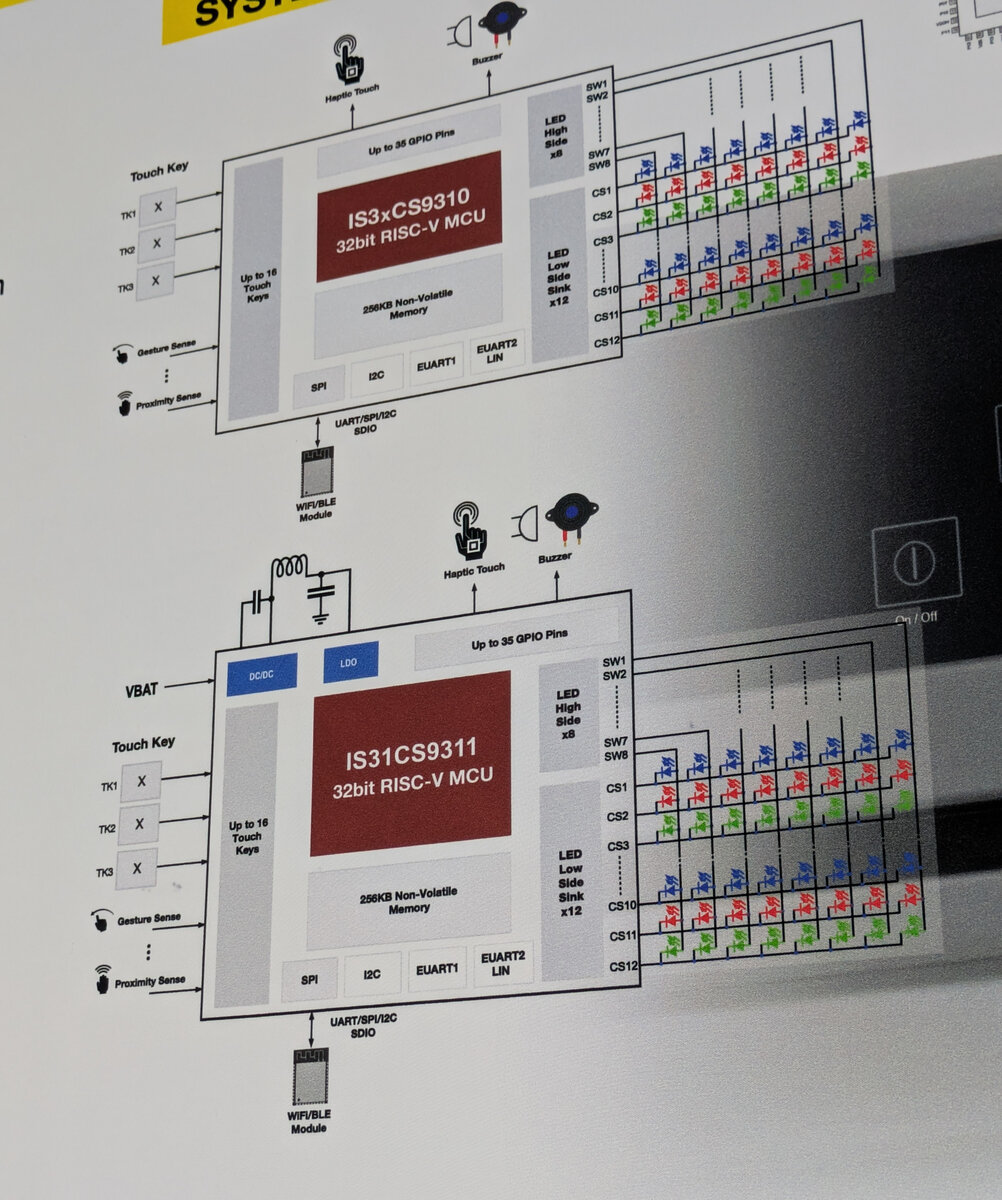
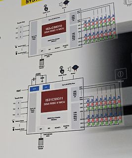
Blockschaltbild eines RISC-V Mikrocontrollers
EUART2 LIN, WIF/BLE Module, LDO, VBAT, Buzzer, Haptic Touch, Up to 35 GPIO Pins, SW1 bis SW8, LED High Side x8, LED Low Side Sink x12, CS1 bis CS12, IS31CS9311 32bit RISC-V MCU
-
 Bild
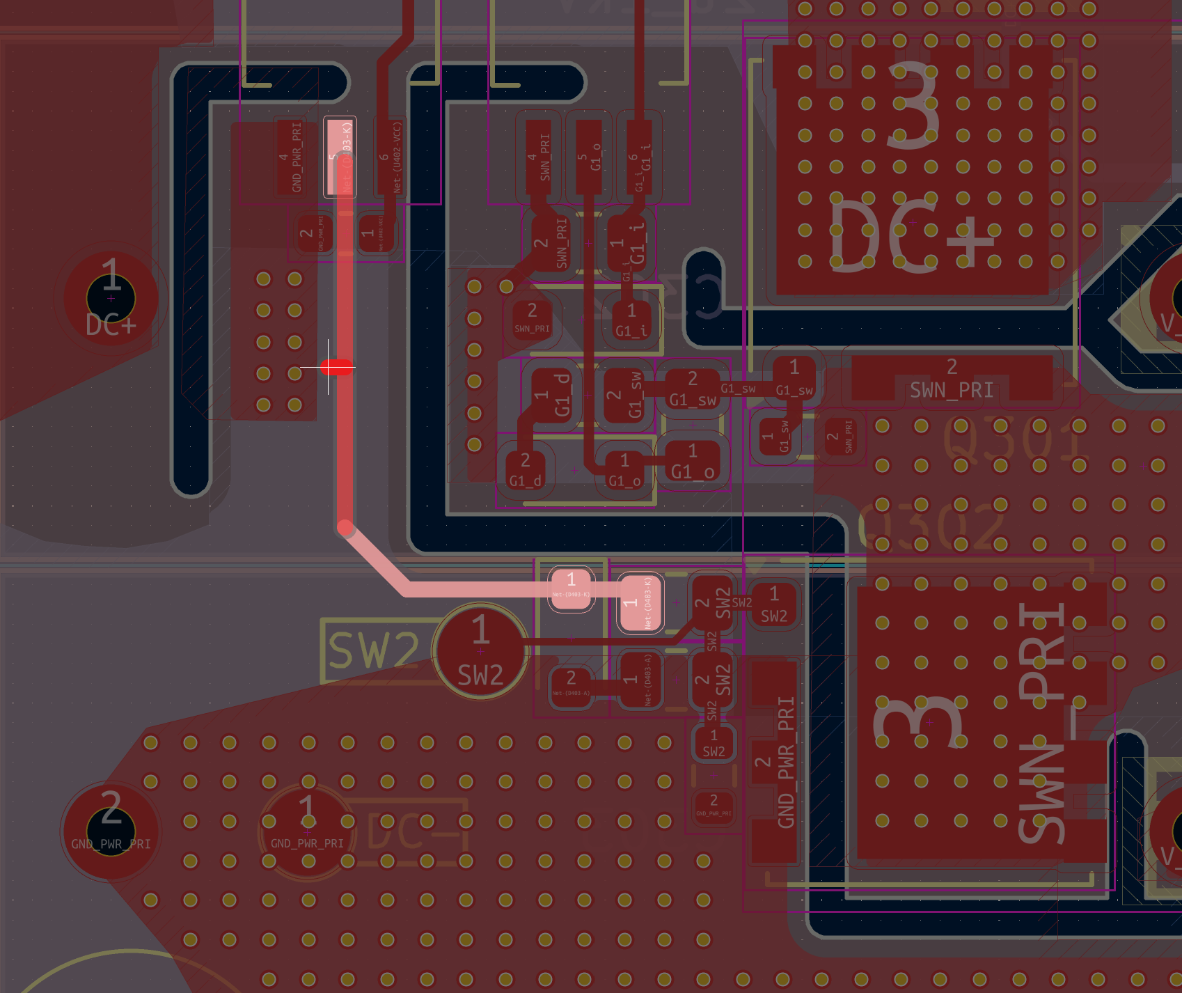
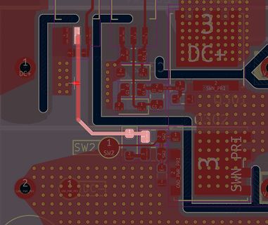
Ausschnitt eines PCB-Layouts
DC+, GND_PWR_PRI, SWN_PRI, G1_t, G1_d, G1_o, G1_sw, SW2, SWN_PRI
-
Thread
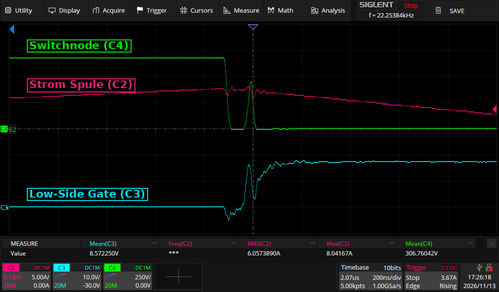
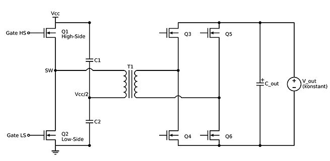
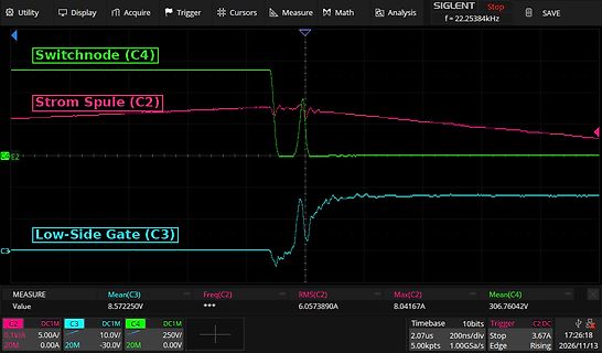
SiC Mosfet bei Dual Active Half Bridge: unerklärliches verhalten bei Halbbrücke / Low Side.
das Low-Side-Gate kurz auf ca. -5 V gezogen (vermutlich Miller über Cgd). 3. Die Switchnode bleibt ca. 60 ns bei 0 V. Genau in dem Moment, in dem das Low-Side-Gate einschaltet, steigt die Switchnode aber nochmal
High-Side ein), tritt das Problem nicht auf. Es betrifft nur die Flanke High-Side aus → Low-Side ein. Was wir schon probiert haben: - Trafo getauscht → keine Änderung - Gatewiderstände erhöht → keine Besserung
-
 Bild
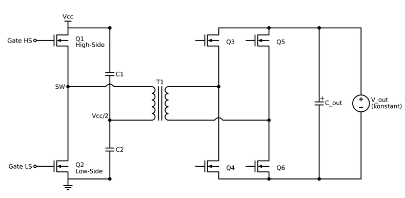
Schaltplan eines Full-Bridge-Wandlers mit Transformator
Vcc, Gate HS, Q1 High-Side, SW, C1, T1, Q3, Q5, V_out (konstant), C_out, Vcc/2, C2, Q2 Low-Side, Gate LS, Q4, Q6
-
 Bild
Oszilloskop-Messung von Schaltknoten, Spulenstrom und Gate-Signal
Cursors Measure Math Analysis SIGLENT Stop SAVE f = 22.25384kHz Switchnode (C4) Strom Spule (C2) Low-Side Gate (C3) MEASURE Value Mean(C3) 8.572250V Freq(C2) *** RMS(C2) 6.0573890A Max(C2) 8.04167A Mean(C4) 306.76042V C2 0.1V/A C3 5.00A C4 0.00A DC1M 10.0V 250V 0.00V Timebase 2.07us 10bits 200ns/div Trigger
-
 Bild
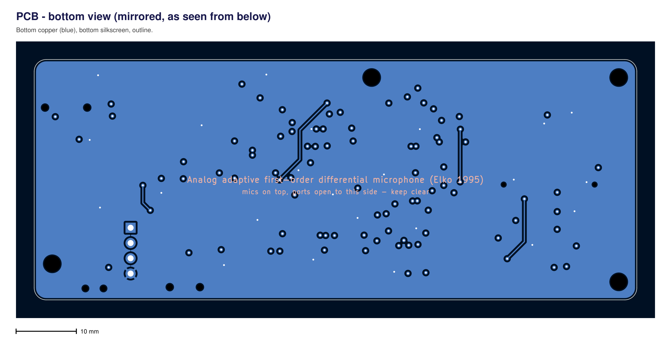
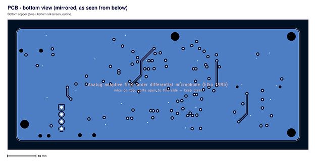
PCB-Layout der Unterseite eines analogen Mikrofon-Adapters
Analog adaptive first order differential microphone (Elko 1995) mics on top, ports open, to this side - keep clear 10 mm
-
 Bild
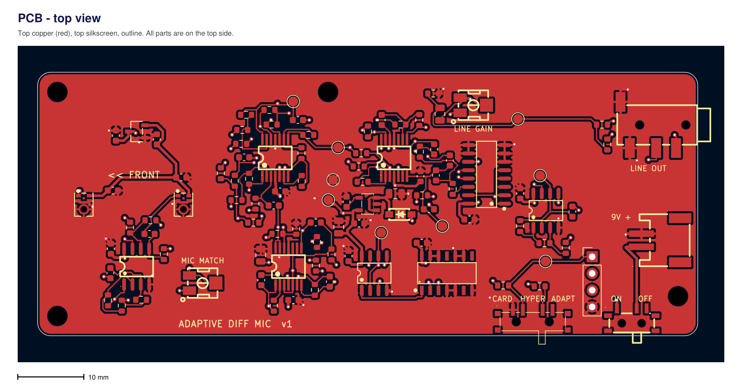
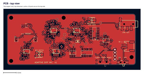
PCB-Layout einer Mikrofon-Schaltung
PCB - top view Top copper (red), top silkscreen, outline. All parts are on the top side. FRONT MIC MATCH ADAPTIVE DIFF MIC v1 LINE GAIN LINE OUT 9V + CARD HYPER ADAPT ON OFF 10 mm
-
 Bild
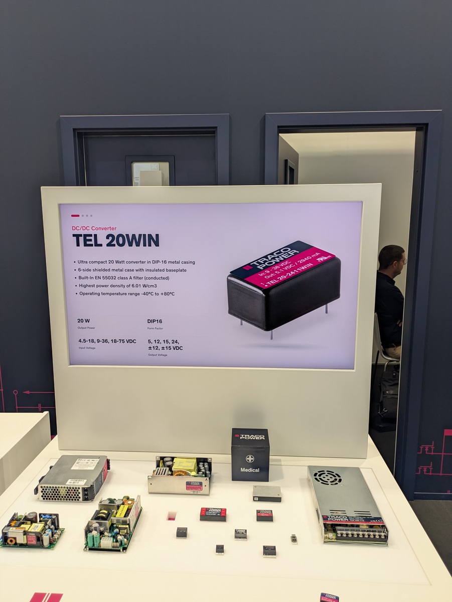
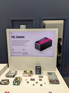
Ausstellung von DC/DC-Konvertern und Netzteilen
DC/DC Converter TEL 20WIN TRACE POWER Ultra compact 20 Watt converter in DIP-16 metal casing 6-side shielded metal case with insulated baseplate Built-In EN 55032 class A filter Highest power density of 6.01 W/cm3 Operating temperature range -40C to +80C 20 W DIP16 From Factory Output Voltage 4.5-
-
Thread
current transformer - was mißt dieser? SCT010T-D
-10-20-30-50-80a-rated-output-0-333v?_pos=1&_sid=66b146ed5&_ss=r). Diese funktionieren dann wirklich von 0A-Maximalstromstärke. Was meinst Du wohl warum der TO erst ab 0,5A was am Ausgang misst?
https://www.poweruc.pl/products/split-core-current-transformer-sct010t-d-rated-input-5a-50a?_pos=1&_sid=39495f6c2&_ss=r an.
-
 Bild
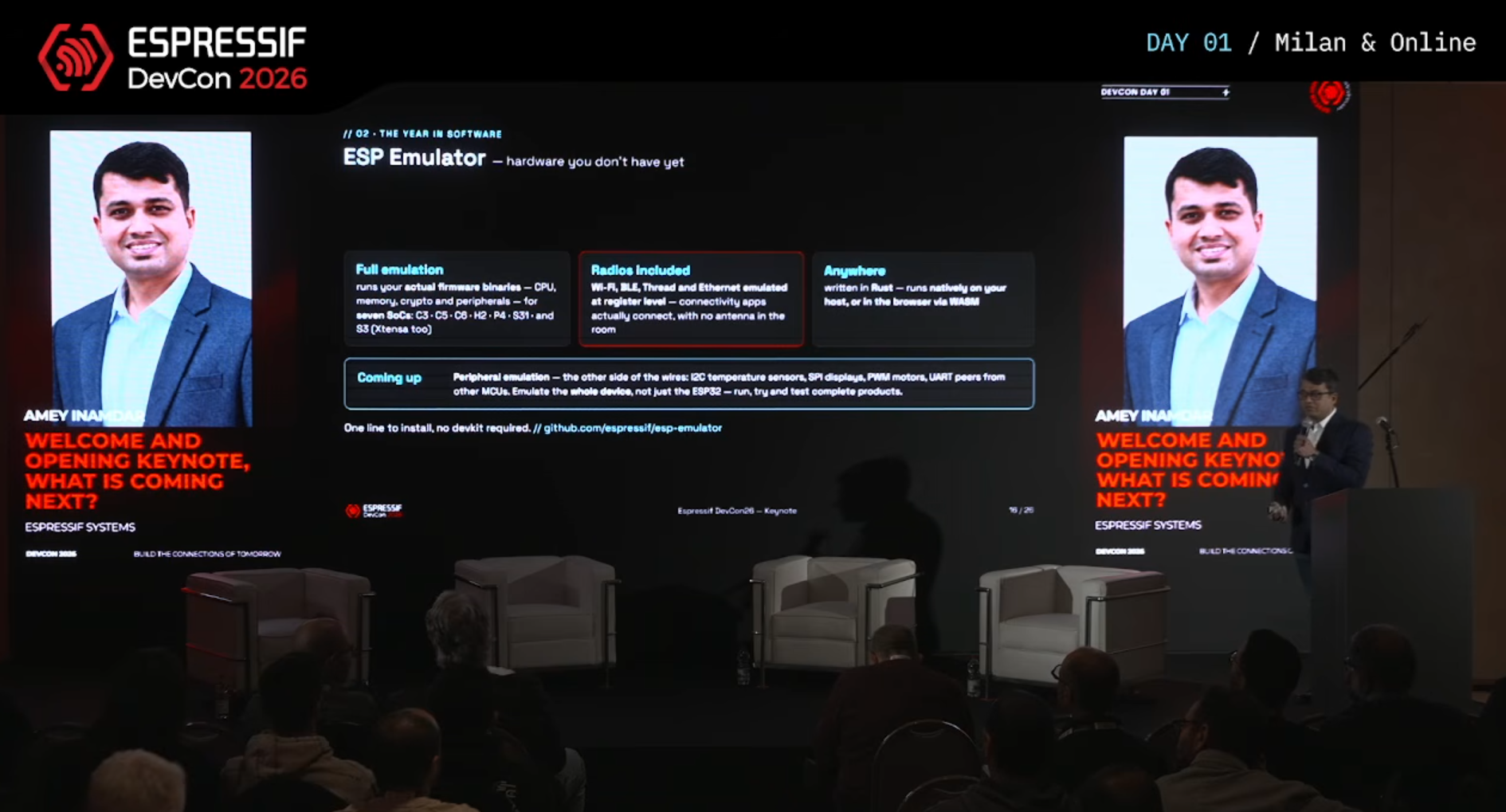
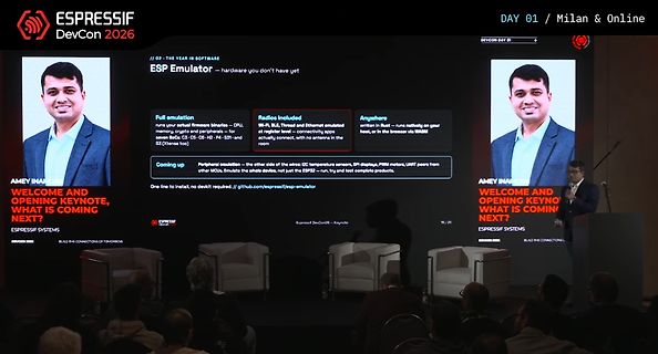
Präsentation von Espressif DevCon 2026
in Rust - runs natively on your host, or in the browser via WASM Peripherals emulation - the other side of wires: I2C temperature sensors, SPI displays, PWM motors, UART peers from other MCUs. Emulate the whole device, not just the ESP32 - run, try and test complete products. One line to install, nodevkit
-
Thread
Bietet hier jemand Chip-Level-Reparaturen als Dienstleistung an?
gun to direct hot air on the pins around the package until package is loose, then push it to the side (this could take a minute or two) > > 4) Remember to also direct air gun to the center of the package where the PowerPad is soldered to the board. Im Bereich Karlsruhe hatte ich mal mit der Firma
-
Thread
ABE Desktop: kostenloses EDA unter Windows, öffnet Eagle-Projekte – Tester für Zusammenarbeit gesuch
– the launcher falls back to X11 (XWayland) as intended. "Zu viele Weiterleitungen": a server-side issue on my side (partner list and marketplace catalogue not published yet), not your system. Nothing to do on your end. radv warning: comes from the Mesa driver for your RX 9060, not from ABE –
-
Thread
I'm looking for a specific and rare HDMI adapter for completing my DIY project
Mario F. schrieb im Beitrag #8106689: > HDMI type A male…and the other side is the micro HDMI FEMALE port https://www.reichelt.de/de/de/shop/produkt/adapter_hdmi_micro_d_buchse_auf_hdmi_a_stecker-145228
already using two HDMI adapters...the same adapters that you suggested...HDMI type A male and the other side micro HDMI FEMALE.
-
 Bild
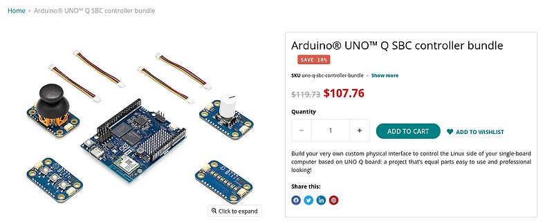
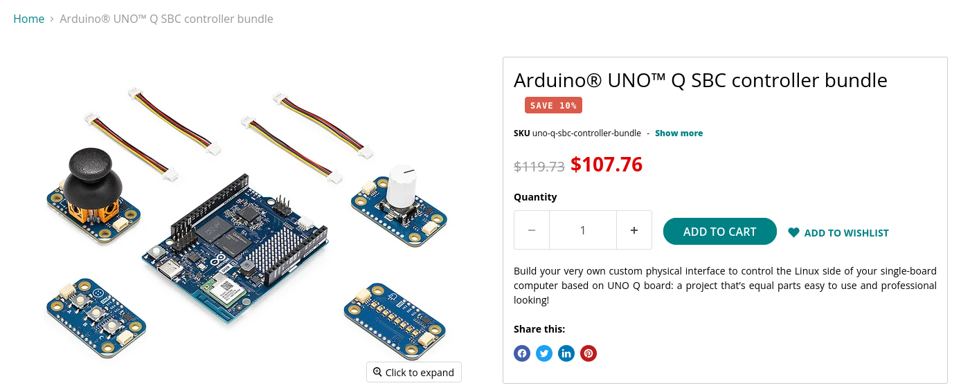
Arduino UNO Q SBC Controller Bundle Set
Quantity ADD TO CART ADD TO WISHLIST Build your very own custom physical interface to control the Linux side of your single-board computer based on UNO Q board: a project that's equal easy to use and professional looking! Share this: